American Journal of Engineering Research (AJER)
e-ISSN: 2320-0847 p-ISSN : 2320-0936
Volume-4, Issue-7, pp-123-132
www.ajer.org
Research Paper Open Access
3D finite element modeling of chip formation and induced
damage in machining Fiber reinforced composites
R. El Alaiji
1, 2, L. Lasri
1, A. Bouayad
2 1(Département Génie Mécanique et Structures, ENSAM/ Université My Ismail, Maroc)
2
(Département Matériaux et Procédés, ENSAM/ Université My Ismail, Maroc)
ABSTRACT:
With the increasing demand for composite materials in many applications such as aerospace and automotive, their behavior needs to be thoroughly investigated, especially during and after failure. In the present work a three-dimensional (3D) finite element (FE) model is developed to study the machining of unidirectional (UD) carbon fiber reinforced polymer composite (CFRP). Chip formation process and ply damage modes such as matrix cracking, fiber matrix shear, and fiber failure are modeled by degrading the material properties. The 3D Hashin failure criteria are used and implemented in the commercial finite element program Abaqus, using a VUMAT subroutine. The objective of this study is to understand the 3D chip formation process and to analyze the cutting induced damage from initiation stage until complete chip formation. The effect of fiber orientation on cutting forces is investigated. The numerical results have been compared with experimental results taken from the literature and showing a good agreement.Keywords -
Chip formation, composites, finite element analysis (FEA), machining, modeling.I.
INTRODUCTION
In recent years, the application of composite materials has increased in various areas of science and technology due to their special properties, namely for use in the aircraft, automotive, defense, aerospace and other advanced industries. These materials are characterized by the high mechanical properties (strength, stiffness, etc.), light weight and good damage resistance over a wide range of operating conditions, making them an attractive option in replacing conventional materials for many engineering applications. Although the components are usually made near-net-shape, achieving dimensional and assembly specifications of the workpiece requires cutting operations such as milling [1] and drilling [2]. However, machining composite materials is quite a complex task owing to its heterogeneity, and to the fact that reinforcements are extremely abrasive. It has been shown that the machining could cause various damages, such as matrix cracking, fiber-matrix shearing, and fiber breakage. That is why the development of knowledge on the composite behavior is considered as a challenging task to manufacturing engineers.
The methods used in studying the machining of composites have been diverse, and the investigations can be generally divided into three categories: experimental studies focusing on the macro/microscopic machinability of composites, simple modeling using conventional cutting mechanics, and numerical simulations
that treat a composite as a macroscopically anisotropic material or concentrate on the reinforcement–matrix
interaction microscopically.
The study done by Koplev et al. [3, 4] is considered as one of the first real attempts at understanding the machining behavior of fiber reinforced composites. They conducted experimental studies on the orthogonal cutting of carbon fiber-reinforced polymer composites (CFRP). Two important results were observed: the chip formation mechanism was a series of fractures observed in the fibers and a rougher surface was observed for 90° fiber orientation samples as compared to 0° fiber orientation. Similar observations were later made by several authors [5-9]. All these authors observed that the chip formation is highly dependent on the fiber orientation.
composite materials. Arola and Ramulu [10] and Arola et al. [11] analyzed orthogonal cutting of unidirectional fiber-reinforced polymer composites using the finite element method. They used a dual fracture process to simulate chip formation incorporating both the maximum stress and Tsai-Hill failure criteria. The obtained cutting forces were found in good agreement with experimental values. However, the thrust forces remain very low and far from those obtained experimentally. Other authors such as Mahdi and Zhang [12] also proposed a 2D cutting force model with the aid of the finite element method. These authors have shown the influence of the fiber orientation on the cutting forces. The obtained results are satisfactory compared with experimental measurements. Rao et al. [13] developed a three-dimensional macro-mechanical finite element (FE) model to study the machining response of unidirectional (UD) carbon fiber reinforced polymer composites. It was found that the cutting force increases with fiber orientation and depth of cut but is less influenced by rake angle. Lasri et al. [14] have used a FEM approach and homogeneous equivalent material (HEM) to study the orthogonal cutting of unidirectional Glass Fiber Reinforced Polymer (GFRP) composites. Their model takes into account the concept of the stiffness degradation and three failure criteria have been considered: Hashin, Maximum Stress and Hoffman criterion to study the mechanisms of chip formation, machining forces and induced damage. These criteria have been implemented in a 2D numerical model using a User-Defined Field Variables (USDFLD) subroutine [15]. In their study, the authors obtained valid cutting forces but the thrust forces remain lower than those obtained experimentally. Recently Zenia et al. [16] developed a 2D finite element model to analyze the chip formation process and subsurface damage when machining the unidirectional CFRP composites (carbon
fiber reinforced polymer). Their approach is based on combined elastoplastic–damage model taking into account
the stiffness degradation of mechanical properties in the material response. The obtained results in terms of the chip formation process, prediction of cutting forces and induced damage are satisfactory compared with experimental measurements.
The objective of this study was, therefore, to develop a 3D finite element model to analyze the physical mechanisms responsible of the chip formation process, to predict the cutting forces and to simulate the cutting induced damage.
II.
FINITE
ELEMENT
MODEL
2.1.
GEOMETRY AND BOUNDARY CONDITIONS
Experimental studies in composites cutting are expensive and time consuming. Moreover, their results are valid only for the experimental conditions used and depend greatly on the accuracy of calibration of the experimental equipment and apparatus used. An alternative approach is numerical methods. FEM is the most frequently used to predict the machining response of metals and composites. The goal of finite element analysis (FEA) is to predict the various outputs of the machining process as the cutting force, stresses, chip geometry. In this study a 3D finite element model was developed using the commercial software Abaqus/Explicit v6.11. It consists of a three-dimensional orthogonal cutting model (Fig.1). It only takes account of the area near the edge radius of the tool (1 5 0 0m* 1 5 0 0m* 1 5 0 0m ). The cutting tool is assumed to be in contact with the
proportion of a workpiece inclined according to the fiber orientation θ [11, 17]. The machined material is carbon
fiber reinforced polymer composites. The properties used during FE simulation is adapted from [13] and are listed in Table 1.
Concerning the boundary conditions, the workpiece is fixed while the cutting tool moves. The under
edge of the workpiece is constrained against horizontal and vertical displacements (ux uy 0). The
displacements of extreme left side are also restrained (ux=0) in the cutting direction. The cutting tool is
modeled as a rigid body with geometry defined by the rake and clearance angles ( and ) and tool nose
radiusr . A reference point was defined to control the movement of Cutting Tool against the workpiece. The
elements employed are eight-node brick elements (C3D8R). Mesh convergence tests were conducted and finally, fine mesh is used in the vicinity of the contact zone between the tool and workpiece while coarse meshes
are used elsewhere. The element size employed in the in fine mesh domain is around5m* 5m* 5m and
Figure 1: Schematic view of the3D orthogonal cutting model showing the tool geometry and
composite workpiece. is the fibre orientation, the tool rake angle, the flank angle andrthe tool nose
radius. (123) is the principal material system, ap being the depth of the cut
2.2
COULOMB FRICTION
Friction at the tool–chip interface is a very complex process. One of the methods is to experimentally
obtain the coefficient of friction and apply it as a constant over the tool–chip contact length. In most studies, the
Coulomb friction model is used in machining simulations: The Coulomb friction law and Tresca shear stress
limit to model the sticking and sliding conditions at the tool–chip interface. In the study by Pramanik et al. [18],
the friction at the tool–chip interface was controlled by a Coulomb limited Tresca law, which is expressed by
Eqs. (1) and (2).
n
(1)
lim (2)
Where li m is the limiting shear stress, is the equivalent shear stress, is the friction coefficient and n is the normal stress (contact pressure). For the present study, the coefficient of friction between the tool-work interface was taken as a constant value of 0.3, however, it is understood that with higher fiber orientation this coefficient of friction will not remain constant and can vary with normal load or machining speed. Elastic properties of UD-CFRP composite Longitudinal modulus: E1 (GPa) 147
Transversal modulus: E2(GPa) 10.3 Transversal modulus: E3(GPa) 10.3 Shear modulus in 1-2 plane: G12 (GPa) 7
Shear modulus in 2-3 plane: G23 (GPa) 3.7 Shear modulus in 1-2 plan: G12 (GPa) 7
Poisson’s ratio: 1 2 0.27 Poisson’s ratio: 2 3 0.54 Poisson’s ratio: 1 3 0.27 Ultimate strength (MPa) Longitudinal tensile strength: Xt 2280
Longitudinal compressive strength: Xc 1725
Transverse tensile strength: Yt 57
Transverse compressive strength: Yc 228
Tensile strength across the fiber direction : Zt 57
Compressive strength across the fiber direction : Zc 228
Shear strength in 1-2 plane: Sxy 76
Shear strength in 2-3 plane: Syz 52
Shear strength in 1-3 plane: Sxz 46
2.3 HASHIN 3D FAILURE CRITERIA
Failure modes in unidirectional fiber composites are strongly dependent on ply orientation, loading direction, specimen geometry. There are four basic modes of failure that occur in a composite structure. These failure modes are; matrix cracking, fiber-matrix shearing, fiber failure, and delamination. Delamination failure, however, is not included in the present study.
The onset and the type of the failure can be predicted using different theories published by different authors; a general overview of failure theories is reported in [19]. Several authors used the 2D Hashin criteria to predict failure during machining FRP composites [14, 17]. From their works it was concluded that 3D failure criteria would be needed when 3D out of plane components of the stress are important. In the present work, 3D Hashin criteria have been chosen to produce the various induced damages responsible for chip formation.
The 3D Hashin criteria are summarized below.
Matrix tensile cracking can result from a combination of transverse,2 2, and shear
stress,1 2, 1 3and 2 3. The failure index can be defined in terms of these stresses and the strength
parameters Y and S. when the index, em, exceeds unity, failure is assumed to occur. Assuming linear
elastic response, the failure index has the form:
2 2
2
2 y y x y y z
m
t x y y z
e
Y S S
for 2 2 0
Matrix compressive failure occurs due to a combination transverse compressive stress and shear stress.
The failure criterion has the same form as that for matrix tensile cracking:
2 2
2
2 y y x y y z
m
c x y y z
e
Y S S
for 2 2 0
Where Ytis the strength perpendicular to the fiber direction in tension, Yc is the strength perpendicular
to the fiber direction in compression, andSx y, Sy zare the in-plane shear and transverse shear
strengths, respectively.
Fiber matrix shearing failure result from a combination of axial stress (1 1) and the shear stresses.
The Failure criterion has the form:
2
2 2
2 y y x y x z
f s
c x y x z
X e S S
for 1 1 0
Fiber tensile failure
2 2
2
2
t
x y
x x x z
f
x y x z
X e S S
for 1 1 0
Fiber compressive failure
2 2 c x x f X e
for 1 1 0
Where Xt is the tensile strength along the fiber direction Xc is the compressive strength along the fiber
2.4 PROGRESSIVE FAILURE AND MATERIAL DEGRADATION
PFA are based on two main ingredients: failure criteria to be checked locally, i.e., in each Gauss point of the FE mesh, and a degradation rule, to be applied once the failure criterion is satisfied in some points. The Hashin criteria are the most used in PFA. The degradation rules usually are applied once a damage mode is activated on the basis of a local failure criterion; they basically consist in the reduction of appropriate components of the stiffness matrix. Most frequently sudden, brittle degradation is imposed, i.e., stiffness components are reduced to zero. After the stiffness components have been reduced, the stresses are recalculated with the new global stiffness and then the load is again increased. Kutlu and Chang [20, 21] have applied
Hashin’s failure multimode criterion; subsequently the local properties are reduced according to the failure type predicted by the failure criterion.
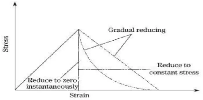
The sudden reduction of stiffness properties can sometime give problems of convergence, in other words it is difficult to reachieve equilibrium after sudden degradation. To overcome the above difficulty some
authors adopt a gradual reduction (see Fig. 2),a reduction factor β has been introduced. The degraded material
properties (see Table 2)are calculated by multiplying the original value with the reduction factor β.
A typical scheme for the progressive failure analysis is illustrated in Fig. 3.
Figure 2 Properties degradation behavior in damage composite
Yes
No
Check for completion
chip formation
Stop
Material property
degradation
Load increment
Start
FE model setup
Stress analysis
Failure Analysis
No
Check for
failure
Yes
2.5
VUMAT SUBROUTINE
The experimental observations conducted by several authors like Koplev [3,4] and Wang et al. [7] showed that composite chips are formed through a series of brittle fractures under high mechanical loading. Consequently, we consider in this work that during machining process, a brittle behaviour dominates during the chip formation process. To analyze the later, the progressive failure analysis has been implemented in Abaqus using the subroutine VUMAT, written in FORTRAN. The VUMAT subroutine (user-defined material model for Abaqus/Explicit) allows the use of solution defined variables, noted SDV [15]. To simulate the fractures responsible of the chip formation process, the elastic properties are made to be dependent on three solution variables, SDV 1, SDV 2, and SDV 3. The first solution variable represents the matrix failure index, the second the fiber-matrix shearing failure index, and the third the fiber failure index.
As depicted in Fig. 3, at the beginning of the analysis, the solution defined variables are set equal to zero in all integration points and the material properties are equal to their initial values. Then, the tool advancement generates an increased mechanical loading. For each displacement increment, several iterations are needed before the simulation converges to an equilibrium state. At the end of each increment, stresses and failure indices are computed at the integration points of each element. If the failure index exceeds 1, the associated user-defined field variable SDV is set equal to 1 and remains at this value until the end of the process, the material properties are automatically degraded, see Table 2. The procedure is repeated until the complete chip formation.
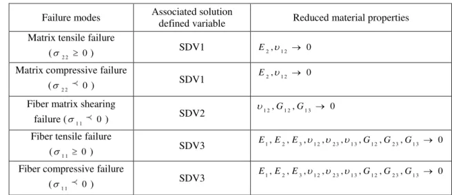
Table 2Hashin criteria with five modes and associated degradation rules.
III.
NUMERICAL
RESULTS
3.1
CHIP FORMATION PROCESS
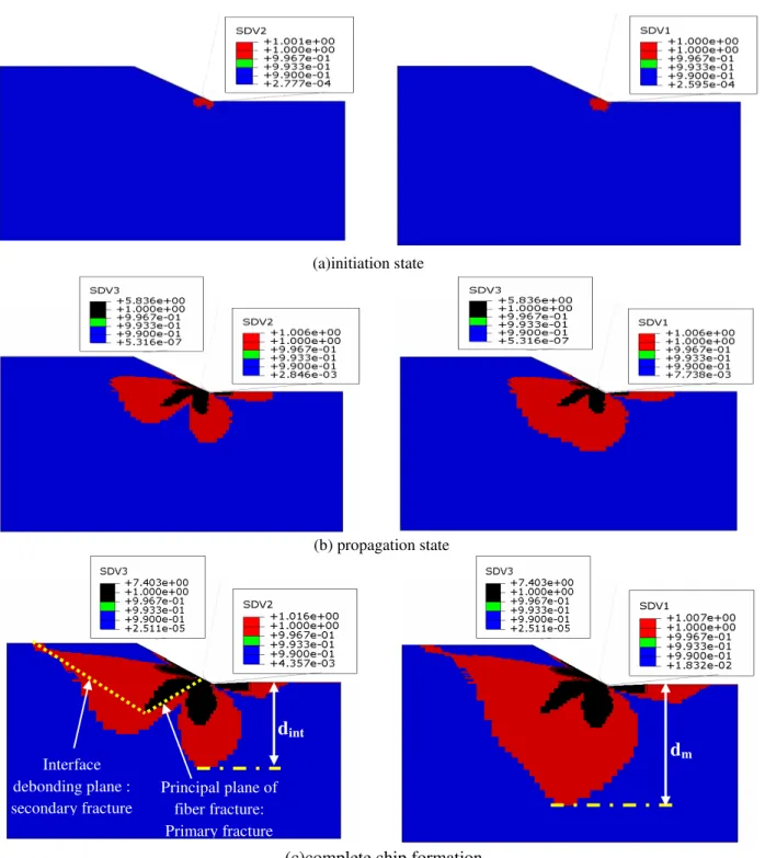
As said before, the chip formation has been considered completed when both fiber matrix shearing(interface debonding) reaches the free workpiece surface, and the fracture of the fiber(primary fracture) is verified and attached with interface debonding .
Fig. 4 shows failure modes responsible of the chip formation process for the fiber orientation of 30°, rake angle of 10°, clearance angle of 6°, depth of cut of 200µm and tool nose radius of 50 µm at different tool advancement stage. SDV1, SDV2 and SDV3 indicate the matrix cracking mode, the fiber matrix shearing mode (interface debonding) and the fiber fracture mode, respectively.
It can be seen that at the beginning of the process, damage is originated at the chip/tool contact at the zone close to the cutting edge radius. Matrix cracking and fiber matrix shearing occur first and followed by fiber fracture. Damage of different components propagates until the complete chip formation. The progression damage at the matrix and the interface occurs in the parallel direction to the fiber axis. The fiber fracture can also be observed localized in a plane with a specific direction.
The predicted damages are very similar to the primary and secondary fracture previously reported by Wang et al. [7] and Arola et al. [10, 11]. The ruptures that were represented in the model by SDV3 and SDV2 were found to be consistent with the primary and secondary fracture planes, respectively. The primary fracture is defined by fibers fracture, while the secondary fracture is defined by interface debonding. From many experimental data, it was found that the nature of the chip formation largely depends on the fiber orientation Wang et al. [7], Arola et al. [8], Rao et al. [13] and Zitoune et al. [22], for this reason other simulations have been performed to show the effect of the fiber orientation on the chip formation process. Fig.5 shows the damage mode responsible for the chip formation for the case of fiber orientation between 15° and 75°. It can be
Failure modes Associated solution
defined variable Reduced material properties
Matrix tensile failure
(2 2 0)
SDV1 E2,1 2 0
Matrix compressive failure
(2 2 0)
SDV1 E2,1 2 0
Fiber matrix shearing
failure (1 1 0)
SDV2 1 2,G1 2,G1 3 0
Fiber tensile failure
(1 1 0)
SDV3 E1,E2,E3,1 2,2 3,1 3,G1 2,G2 3,G1 3 0
Fiber compressive failure
(1 1 0)
d
mPrincipal plane of fiber fracture: Primary fracture Interface
debonding plane : secondary fracture
d
intseen that all failure modes (matrix cracking, fiber matrix shearing and fiber failure) initiated near the tool nose. as and when as the tool advances into the work material, fiber matrix shearing (sdv2) and matrix cracking (sdv1) propagate in the parallel direction to the fiber axis. However, the fibers fracture (sdv3) propagates in a plane with a specific direction, which fiber orientation dependent. These results are in good agreement with the experimental observations of Iliescu et al. [23], Arola et al. [10], and Wang et al. [7]. Another important point of this work concerning the plane of primary fracture (fibers fracture) can be highlighted.
(a)initiation state
(b) propagation state
(c)complete chip formation
Figure 4: Damage modes responsible of the chip formation process when the fiber orientation is kept equal to 30◦.
(a) Initiation stage. (b) Propagation stage. (c) Chip formation completed. The cutting conditions are: 1 0 ,
6 ,
ap2 0 0m, r 5 0m.SDV1, SDV2 and SDV3 indicate matrix cracking mode, fiber–matrix shearing or
interface debonding mode, and fiber fracture mode, respectively.
d
m andd
int represent the depth of the damagedPrincipal plane of fiber fracture: Primary fracture Interface
debonding plane : secondary fracture
d
intInterface debonding plane: secondary
fracture
Principal plane of fiber fracture: Primary
fracture
Interface debonding plane : secondary fracture
Principal plane of fiber fracture: Primary fracture
(a) θ=15° (b) θ=30°
(c) θ=45° (d) θ=60°
(e) θ=75°
Figure 5: Chip formation process and damage mechanisms predicted by the 3D finite element model with respect
to the fiber orientation. The cutting conditions are: 1 0 , 6 , ap 2 0 0m, r 5 0m.
Principal plane of fiber fracture: primary fracture Interface
debonding plane: secondary fracture Principal plane of
fiber fracture: primary fracture Interface
Fiber orientation (°) C u tt in g fo rc e p e r u n it th ik n e s s (N /m m )
0 20 40 60 80
0 5 10 15 20 25 30 35 Fc_experimental [13] Fc_simulation
Fiber orientation (°)
T h ru s t fo rc e p e r u n it th ik n e s s (N /m m )
0 20 40 60 80
0 5 10 15 20 25 30
Ft experimental [13] Ft simulation [13]
3.2
CUTTING FORCES
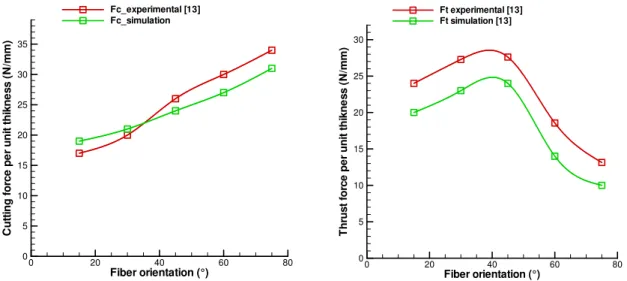
In order to validate the 3 finite element model, the reaction forces on the cutting tool from simulations were compared to cutting forces from experimental data presented by Rao et al. [13]. Cutting forces are calculated at each increment of time during the displacement of the cutting tool following the cutting direction.
From a comparison of the experimental and numerical results in Fig. 6(a) it was found that the trend in principal cutting force with fiber orientation obtained from the finite element model agreed very well with experimental results. They increase significantly with increasing fiber orientation. The minimum cutting force occurred in the cutting of 15° unidirectional material.
Thrust forces from the numerical model were an order of magnitude lower than experimental values as evident in Fig.6(b) They increase gradually up to 45° fiber orientation and then decrease slowly till 75° fiber orientation. This can be explained by the use of HEM, and by the bouncing back phenomenon described by Wang and Zhang [24] and which not taken into account in this work.
Figure 6: variation of machining forces with fiber orientation. (a) Cutting force, (b) Thrust force. The cutting
conditions are: 1 0 , 6 , ap 2 0 0m, r 5 0m.
3.3
INDUCED SUBSURFACE DAMAGE
Several types of damage are introduced during the machining operations, one of the most important results of this study is to predict the subsurface damage such as matrix cracking (SDV1), fiber matrix debonding (SDV2) induced by the cutting process, and to analyze its interaction with the fiber orientation. The failure
index contours defined by SDV’s contours display the damaged zones. Fig.4(c) shows an example of the
predicted subsurface damage obtained, in the case of 30° fiber orientation, in the matrix and at the interface.
d
mand
d
int represent the depth of subsurface damage in the matrix and at the interface, respectively. Fig.7 showsvariation of subsurface damage with fiber orientation. The damage tends to increase with the advancement of the tool in the machined material.
Fiber orientation (deg)
S u b s u rf a c e d a m a g e (µ m )
0 20 40 60
0 50 100 150 200 250 300 350 400 450 500 dint dm
Figure 7:variation of subsurface damage with fiber orientation.
d
int,d
m indicate damage in matrix and damageIV.
C
ONCLUSIONA 3D finite element progressive failure analysis was developed for chip formation in 3D orthogonal
machining of unidirectional fiber reinforced plastics for fiber orientation 15deg ≤ θ ≤ 75deg. The progressive
failure analysis includes matrix cracking, fiber matrix debonding and fiber breaking. The mode was verified from a comparison of cutting forces with experimental results taken from the literature. The following conclusions are drawn:
(i) matrix cracking and fiber matrix debonding are firstly detected and progress along the fiber
direction,
(ii) the fiber fracture occurs later than that of the matrix cracking and the fiber matrix debonding,
(iii) the damage of different components: fiber, matrix, and fiber matrix interface, then
simultaneously progresses until the complete chip formation process,
(iv) the chip formation process was strongly dependent on fiber orientation,
(v) The current model can easily predict the induced subsurface damage.
Finally, it is important to include the temperature on the mechanical behavior in order to investigate thermal influence on the damage initiation and its growth. .
R
EFERENCESJournal Papers:
[1] D. Kalla, J. Sheikh-Ahmad and J. Twomeya, Prediction of cutting forces in helical end milling fiber reinforced polymers. Int J Mach Tool Manuf, 50, 2010, 882–891.
[2] D. Iliescu, D. Gehin, ME. Gutierrez and F.Girot, Modeling and tool wear in drilling of CFRP. Int J Mach Tool Manuf, 50, 2010, 204–213.
[4] A. Koplev, A. Lystrup and T. Vorm ,The cutting process, chips, and cutting forces in machining CFRP, Composites 14(4), 1983, 371–376.
[5] H. Takeyama and N. Iijima, Machinability of glassfiber reinforced plastics and applications of ultrasonic machining, Annals CIRP, 37(1), 1988, 93-96
[6] T. Kaneeda, CFRP cutting mechanism, Trans. North American Manufacturing Research Institute of SME, 19, 1991, 216-221 [7] D.H. Wang, M. Ramulu, D. Arola, Orthogonal cutting mechanisms of graphite/epoxy composite. Part I: unidirectional laminate,
Int J Mach Tools Manuf,35(12), 1995,1623–38.
[8] D. Arola, M. Ramulu and D.H.Wang, Chip formation in orthogonal trimming of graphite/epoxy, Compos Part A, 27, 1996, 121– 33.
[9] N. Bhatnagar, N. Ramakrishnan, N.K. Naik and R.Komanduri, On the machining of fiber reinforced plastic (FRP) composite laminates, Int J Mach Tools Manuf, 35(5),1995,701–16.
[10] D. Arola and M. Ramulu, Orthogonal cutting of fiber-reinforced composites: a finite element analysis, Int J Mach Tool Manuf, 39(5), 1997, 597–613.
[11] D. Arola, M.B. Sultan, M. Ramulu, Finite element modeling of edge trimming fiber-reinforced plastics, Trans ASME J Eng MaterTechnol,124, 2002,32–41.
[12] M. Mahdi, L. Zhang, A finite element model for the orthogonal cutting of fiber reinforced composite materials, J Mater Process Technol, 113(1–3), 2001,373–377.
[13] GVG Rao, P. Mahajan and N. Bhatnagar, Three-dimensional macro-mechanical finite element model for machining of unidirectional-fiber reinforced polymer composites. Materials Science and Engineering A, 498, 2008, 142–149.
[14] L. Lasri, M. Nouari and M. El-Mansori, Modelling of chip separation in machining unidirectional FRP composites by stiffness degradation concept, Compos Sci Technol, 69, 2009, 684–92.
[15] ABAQUS Documentation for version 6.11-2Dassault systems Simulia; 2011.
[16] S. Zenia, L. Ben Ayed, M. Nouari and A. Delamézière, Numerical prediction of the chip formation process and induced damage during the machining of carbon/epoxy composites, Int J Mech Sci, 90, 2015, 89-101.
[17] L. Lasri, M. Nouari, M. El Mansori, Wear resistance and induced cutting damage of aeronautical FRP components obtained by machining, Wear 271, 2011, 2542– 2548.
[18] A. Pramanik, L.C. Zhang and J.A. Arsecularatne, An FEM investigation into the behavior of metal matrix composites: tool– particle interaction during orthogonal cutting, International Journal of Machine Tools and Manufacture 47, 2007, 1497–1506. [19] A.C. Orifici, I. Herszberg, et al., Review of methodologies for composite material modelling incorporating failure. Composite
structures 86(1-3), 2008, 194-210.
[20] Z. Kutlu and F. K. Chang, Composite panels containing multiple through the-width delaminations and subjected to compression: Part I. Analysis. Composites Struct., 31, 1995, 273–296.
[21] Z. Kutlu and F. K. Chang, Composite panels containing multiple through the-width delaminations and subjected to compression: Part II. Experiments and verification. Composites Struct., 31, 1995,297–314.
[22] R. Zitoune, F. Collombet, F. Lachaud, R. Piquet and P. Pasquet, Experimental calculation of the cutting conditions representative of the long fiber composite drilling phase, Composites Science and Technology 65, 2005, 455–466.
[23] D. Iliescu, D. Gehin, I. Iordanoff, F. Girot and M.E. Gutiérrez, A discrete element method for the simulation of CFRP cutting. Compos Sci Technol, 70, 2010, 73–80.
[24] XM. Wang, LC. Zhang, An experimental investigation into the orthogonal cutting of unidirectional fibre reinforced plastics. Int J MachTools Manuf,43, 2003,1015–22.
Proceedings Papers: