Abstract
The current investigation focused on the development of effective and suitable modelling of reinforced concrete component with and without strengthening. The modelling includes physical and con-stitutive models. New interface elements have been developed, while modified constitutive law have been applied and new com-putational algorithm is utilised. The new elements are the Truss-link element to model the interaction between concrete and rein-forcement bars, the interface element between two plate bending elements and the interface element to represent the interfacial behaviour between FRP, steel plates and concrete. Nonlinear finite-element (FE) codes were developed with pre-processing. The programme was written using FORTRAN language. The accuracy and efficiency of the finite element programme were achieved by analyzing several examples from the literature. The application of the 3D FE code was further enhanced by carrying out the numeri-cal analysis of the three dimensional finite element analysis of FRP strengthened RC beams, as well as the 3D non-linear finite element analysis of girder bridge. Acceptable distributions of slip, deflection, stresses in the concrete and FRP plate have also been found. These results show that the new elements are effective and appropriate to be used for structural component modelling.
Keywords
Finite element, interface element, bond, plate bending element, three dimensional, concrete structure, FRP, non-linear analysis.
Non-Linear Three Dimensional Finite Elements
for Composite Concrete Structures
1 INTRODUCTION
In the analysis of the composite structures, modelling of various structural elements interface (such as beam, truss, plate, membrane, solid element, etc.) should be carefully taken into account. Other-wise, accuracy will not be achieved. Moreover, these issues cannot be handled by using any of the
O. Kohnehpooshi a,* M.S. Jaafar b
a Department of Civil Engineering,
Sanandaj Branch, Islamic Azad Universi-ty, Sanandaj, Iran.
E-mail: [email protected]
b Department of Civil Engineering,
Uni-versiti Putra Malaysia, 43400 UPM Serdang Selangor, Malaysia. [email protected]
* Corresponding author
http://dx.doi.org/10.1590/1679-78253170
above-mentioned elements. Interface translation and rotational degrees of freedom should be consid-ered. Introducing suitable interface elements will solve this problem for specific behaviour.
Attempt was made by Ahmad (1987) to develop a new finite element called Ahmad’s link to represent the interface between bar and concrete. However, the development and application of this particular element in RC component need multi-level generation of the link element but only a few reports are available. Hence, further improvement in the development and generation of this type of element is required.
Interface elements were used to model the bonding between FRP plates and concrete beams by Lu et al. (2006), Niu and Wu (2006) and Abdel Baky et al. (2007). In addition, the interface ele-ments were also used to model the bonding between the FRP plates and concrete components such as slabs (Elsayed et al., 2007), curved concrete beams (Jalili & Chao, 2010) and masonry structures (Waleed et al., 2008; Milani, 2010). Ebead and Marzouk (2004) simulated the behaviour of the con-crete-FRP interface using a very fine mesh to model the adhesive layer that is defined as a linear elastic material. However, Hu et al. (2004), Lundquist et al. (2005), as well as Santhakumar and Chandrasekaran (2004) who have studied the behaviour of retrofitted structures ignored the effects of the interfacial behaviour between the FRP plates and concrete for difficulty in the modelling of interface behaviour. Rodrigues et al.(2015) were modeled the interaction between steel bars and concrete through the use of interface finite elements with high aspect ratio and a damage model designed to describe the bond-slip behavior which proposed by Manzoli et al. (2012).
More recently Vinh (2014) presented an open source one/two dimensional programme to gener-ate zero-thickness cohesive interface elements. Ali Zokaei et al. (2014) proposed a 2D plgener-ate element for the idealization of composite slabs. Interface elements are used to connect the unbonded layers within the composite slab and to model the interface between the bottom slab layer and the founda-tion layer. Khelifa et al. (2015) focused on the flexural behaviour of timber beams externally rein-forced using Carbon Fibre-Reinrein-forced Plastics (CFRP). A cohesive model in the Abaqus software was used to represent the interaction between two adherent surfaces (CFRP and timber). The mesoscale model for concrete was detailed by Eduardo et al. (2016) Attention is given to the strate-gy used for modelling the coarse aggregates and the presentation of the mesh fragmentation tech-nique. The formulation of the interface solid finite element and the continuum tension damage mod-el used to describe its behavior.
Meanwhile, non-linear analysis of the reinforced concrete slab-girder bridge has been carried out by several researchers (e.g. Song et al., 2002; Tianyu et al., 2005; Chansawat et al., 2006; Sulata, 2007, Tong Guo et al. 2016). Most of the investigations have focussed on some specific issues, such as cracking, crushing and yielding, with different elements and computational procedures. Moreover, the development and application of the interface elements, such as Truss-link or the interface be-tween plate bending element and brick element to analyse (static or dynamic) the RC structures, have not been well reported in the literature. Hence, there is a need to combine all these important parameters in research programmes.
was further enhanced by carrying out the numerical analysis of the, three dimensional finite element analysis of FRP strengthened RC beams, as well as the 3D non-linear finite element analysis of girder bridge. Acceptable distributions of slip, deflection, shear and axial stresses in the FRP plate have also been found. These results show that the new elements are effective and appropriate to be used for structural component modelling.
2 PROPOSED FINITE ELEMENT MODEL
2.1 Choice of the Element
In reinforced concrete material the external load is applied to the concrete and the reinforcing bars only receive its part of the load from the surrounding concrete by bond. In the composite struc-tures, the bond between different components of reinforced concrete member has a fundamental role and its neglect is conducted to poor structural response. In the following sections, suitable elements for modelling the concrete, bars, FRP or steel plate and new interface elements are chosen and de-veloped into a realistic model of RC structures with and without strengthening.
The detail for modelling of each element proposed for finite element analysis and physical mod-elling of Reinforced concrete beam is discussed briefly.
2.1.1 Concrete Element
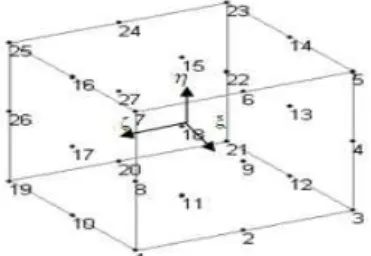
To represent modelling the concrete, twenty seven node Lagrangian brick element (Figure 1), is a powerful element for 3D finite element modelling of concrete. The element has three degrees of free-dom in each node. The element is from lagrangian family. The shape functions for the 27 node La-grangian brick element are generated using zero method and products of three Lagrange polynomi-als which reported by Kohnehpooshi et al (2010).
Figure 1: Twenty seven node Lagrangian brick element.
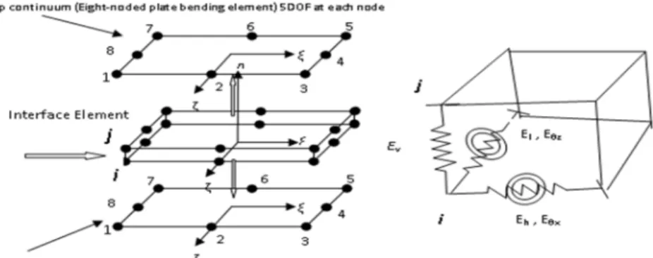
2.1.2 Plate Bending Element
8 node isoparametric plate bending element with 5 DOF (3 translation and 2 rotation) is used to model the steel or FRP plates. The nodal displacements at any node i, are:
where: u , v , w are displacements in x, y and z directions and θ , θ are rotations in the x and y directions. This element, can allow for the transverse shear deformations. Rotations, θ and θ can be expressed as:
θ ϕ And θ ϕ (2)
where: ϕ , ϕ are average shear rotations of the mid surface normal. More detail and formulation of this element has already been presented by Viladkar and co. Workers (1994). Figure 2 shows the mentioned element.
Figure 2: 8 node isoparametric plate bending element with 5 DOF.
2.1.3 Linkage and Truss-Linkage Element
Ahmad et al. (1987) developed the the three-dimensional bond-linkage element to model the inter-face relationship between steel and concrete. This element connects the line and the solid elements together and has two nodes as shown in Fig. 3. The horizontal spring represents the bond stiffness that is parallel with the bar element and acts as a bond between the steel and concrete.
Figure 3: Bond-link element geometry and its orientation in space, Ahmad (1987).
Truss-link element which presented by Kohnehpooshi et al. (2010) is an element that assembled three dimensional truss and linkage elements as a one element as shown in Figure 4. The two link-age elements, each one with two nodes will be assembled with one 3D truss element. Subsequently, the element has four nodes with 3 DOF in each node. Nodes i and j are bar element nodes, and each pair of nodes i, i’ and j, j’ are linkage element nodes as shown in Figure 4. Only one spring element in the direction of the slip is considered. In the other two directions the same displacements for concrete and steel are used with selecting high values of Young's Modulus (E) in these
direc-Concrete
P
Q
L
X’ (l,m,n)
Concrete Concrete
Y’(p,q,o)
Horizontal Spring Vertical spring
Lateral spring
tions, then concrete and steel have same deflections in these directions. More detail and formulation of this element has already been presented by Kohnehpooshi et al. (2010).
Figure 4: Truss-linkage element.
2.1.4 Plate Bending Interface Element
This newly plate bending interface element was developed to connect two plate bending elements. It has 16 nodes with 5 DOF in each node. This element connects 8 nodes of the top plate and the bottom plates with identical coordinates, as shown in Figure 5. Physically, the element does not exist, but its mechanical action for each node is represented by 5 springs which include 3 orthogonal springs that are connected in the horizontal, vertical and lateral directions, as well as 2 rotational springs to the plate elements. The horizontal and lateral spring represents the bond stiffness and also acts as a bond between two adherends material. The vertical and two rotational bonds can also be applied if the bond-slip relation of the vertical deformation and two rotations can be found for the adhesive material. The explicit form of K, for each link node is given as follow.
Figure 5: Plate Bending Interface Element.
10 10 55 45 44 33 23 22 13 12 11 55 45 55 45 44 45 44 33 23 13 33 23 22 12 23 22 13 12 11 13 12 11 10 10 0 0 0 0 0 0 0 0 0 0 0 0 0 0 0 0 0 0 0 0 0 0 0 0 k k k k k k SYM k k k k k k k k k k k k k k k k k k k k k k k k k K (3)
i
jj
’
, ,
, ,
, ,
(4)
, , , , , , , : are direction cosines of the local axis with respect to the global axes , , , , : are the bond-slip modules in the five directions. These are obtained using an idealized form of the bond-slip curves between the two plates:
∆
∆ (5)
where b is the incremental bond stress and Sis the slip from a specified bond-slip curve.
Eq. 3 is the stiffness matrix of the link element to connect the top and bottom continues in just one node. However, there are 8 nodes in the top and the bottom of interface elements. Therefore, the stiffness matrix for the plate interface element includes 8 link elements stiffness matrices that will become 80×80 stiffness matrix, as follows:
10108080 10 10 10 10 10 10 10 10 10 10 10 10 10 10 80 80 1 0 1 0 0 1 0 0 0 1 0 0 0 0 1 0 0 0 0 0 1 0 0 0 0 0 0 1 0 0 0 0 0 0 0 1 K K K K K K K K K SYM (6)
More detail of this element has already been presented by Kohnehpooshi and co. Workers (2010b).
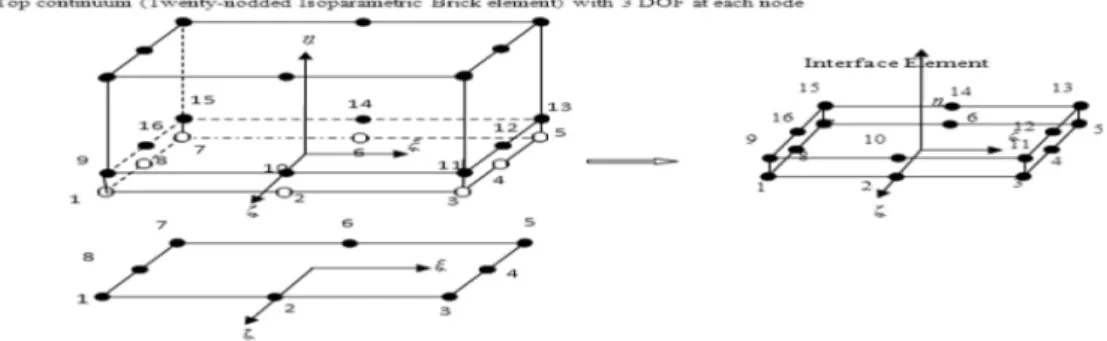
2.1.5 The Interface Element Between the Brick and Plate Bending Elements
Figure 6: Interface Element between the Brick and Plate Bending Elements.
2.1.6 Brick Interface Element
Brick interface element represents the bond modelling between two brick elements. Once again, the interface element has 16 nodes but with 3 DOF in each node. Moreover, there is no rotation degree of freedom. This interface element can also be used to model the interface between the membrane shell elements with 3 translations DOF. More detail and formulation of this element has already been presented by Kohnehpooshi (2012).
2.2 Constitutive Modelling for Bond-Link, Concrete, Steel and CFRP Elements
A few constitutive models of bond stress-slip between the bar and concrete had been developed in the past, as for example: Eligehausen et al. (1983) and Harjli et al. (1995). In this research, bond stresses-slip constitutive model according to CEB-FIP Model Code 1990, based on the Eligehausen Model was used. The shape and relations between bond stresses-slip of this model is shown in Fig-ure 7. Components s , s , s , , and were defined in CEB-FIP Model Code 1990.
for s s (7.1)
for s s s (7.2)
for s s s (7.3)
for s s (7.4)
Non-linear behaviour of the RC components is modelled by taking into account the material nonlinearity of the reinforced concrete structures, which is mainly associated with its compressive yielding. The concrete is assumed to behave according to an elasto-plastic isotropic constitutive relationship under compression. The reinforcing steel is assumed to be elastic–perfectly plastic in tension and compression. The tensile behaviour of the CFRP is assumed as linear elastic until fail-ure.
2.3 Constitutive Modelling for the Bond-Slip Between Concrete and FRP Plates
A few models can be found for the bond-slip model between the FRP plates and concrete in the works by several researchers such as Lu et al. (2005) and Sayed-Ahmed (2009). One of the most accurate bond stress–slip is proposed by Lu et al. (2005). In their study, the behaviour of the FRP/concrete interface was simulated as a relationship between the local shear stress, τ and the relative displacement, s. Three different bond–slip relations have been suggested and are referred to as: (i) precise, (ii) simplified and (iii) bilinear models. In this study, the bilinear model shown in Figure 8 was adopted for its simplicity and little difference in the result as compared to the other two models, as shown in Lu et al. (2005). If max is the maximum bond stress and s0 is the corre-sponding slip, then:
If
,
and If s s s (8.1)where: .5 , . 5 , . 5 / . 5 (8.2)
,
. (8.3)whereb and b, being the widths of the concrete prism and the FRP plate respectively, Gf is the interfacial fracture energy andf is the concrete tensile strength.
Figure 8: The Bilinear Bond–Slip Model by Lu et al. (2005).
2.4 Ottosen Four-Parameter Model Formulation
A failure criterion proposed by Ottosen (1977), known as the four-parameter model, was proposed in this study for formulation and implementation of the developed code as a yield criterion. This
Slip (mm) Before debond Debonding initiation Complete debonding Bond Stress (MPa)
failure surface contains all the three stress invariants with the following characteristics (Bangash, 2001).The surface is smooth and convex with curved meridians, as determined by the constants a and b. It is open in the negative direction of the hydrostatic axis. The trade in the deviatoric plane changes from an almost triangular to a circular shape with the increasing hydrostatic pressure, as defined by λ on the deviatoric plane. The surface is in good agreement with the experimental results over a wide range of stress states, including those where tensile stresses occur. Ottosen defines the analytical failure surface containing all the above characteristics in the following form:
, , (9)
I 1 = σX + σY +σZthe first invariant of the stress tensor (10)
J2=the second invariant of the stress deviator tensor
.5 √ (11)
J3=the third invariant of the stress deviator tensor
(12)
, , (13)
For (14)
For (15)
K and K , a and b are material parameters K Uniaxial compressive cylinder strength for concrete
Uniaxial tensile strength for concrete
As for a>0, b>0, the meridians become curvy, smooth and convex, while the surface opens in a negative direction of the hydrostatic axis. When a=0 and λ=constant, this criterion becomes closer to the Drucker-Prager criterion. When a=0, b=0 and λ=constant, it represents the von Mises crite-rion
3 COMPUTATIONAL PROCEDURES
∆ (16)
accumulate the displacements:
(17)
where,∆ is the residual force vector and is accumulated displacement. and are the total displacement at the endof and iteration. Meanwhile, is the incremental nodal dis-placement during the iteration. The total strain vector after the iteration is:
(18)
where, is the strain at the end of the iteration
The incremental stress vector during the jth iteration is evaluated as follows:
(19)
where is the material matrix based on the state of strain/stress at the chosen gauss point at the end of iteration. Compute total stress vector, , where is the total stresses atthe end of and incremental stresses during the iteration.
While adopting the incremental iterative technique, specification on convergence criteria is nec-essary for the termination of the iterations at particular incremental load step. In the present study, the convergence criterion to terminate the iteration process in the load step is based on the incre-mental displacements and it is expressed as follows:
∥ ∥ ∆ specefic tolerance (20)
3.1 Development of Computer Programmes
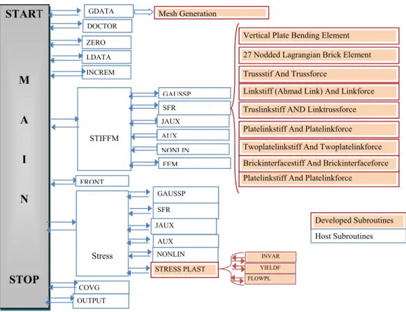
The computational procedures described in the previous sections have been written in the FORTRAN computer language working, under power station environment. The original finite ele-ment programme by Noorzaei (2007) was significantly modified. Eighteen new subroutines integrat-ed with the finite element programme, see Figure 9. The new version of the finite element pro-gramme, called the three-dimensional finite element analysis of the girder bridges (3DFEMGB). The new 3DFEMGB programme has the following features:
(a) Is able to perform a linear elastic analysis of RC members (b) Elasto-Plastic analysis of RC components,
(c) Frontal solver with multi-element and multi degree of freedom features. (d) Pre-processing facilities
Linkage element; Truss-Linkage element; Interface element between plate bending and brick el-ements; Interface element between two plate bending elel-ements; Interface element between two 20 noded Lagrangian brick elements
Figure 9: Flowchart of the Modified Finite Element Programme.
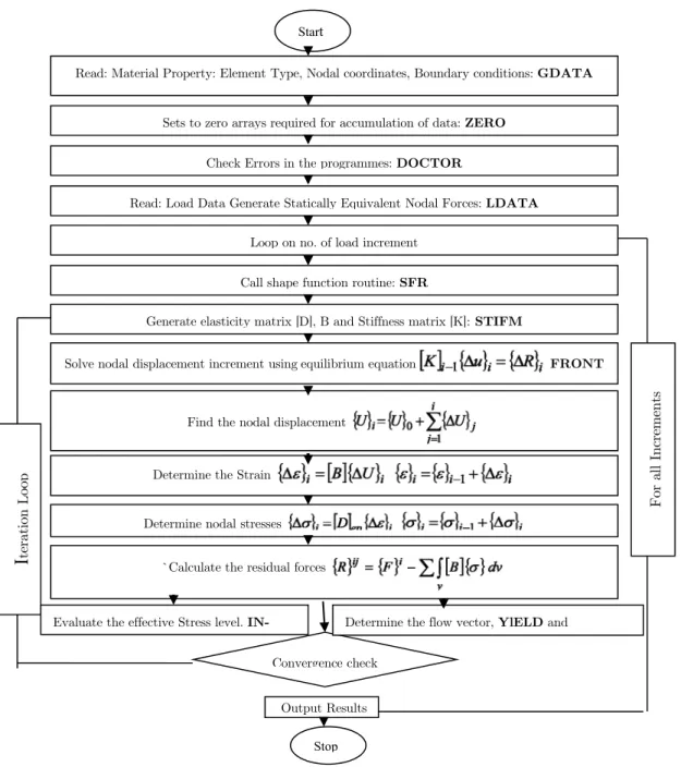
Meanwhile, the inclusion of the above elements involves the implementation of the computation algorithm of the programme. An iterative tangent-stiffness procedure under incremental load was developed to perform a non-linear analysis for reinforced concrete structures. A flowchart of the procedure is shown in Figure 10. In the finite element analysis of structures, if the number of the element increases, it will be difficult to generate the element geometry input data without using any geometry generator tool, and for this reason, a mesh generation programme is written in the FORTRAN language. The programme has the ability to generate 3D solid elements and 2D ele-ments. The outputs of the programme include:
a: Node numbering with their coordinates b: Element numbering,
c: Connectivity of the elements
d: Element type in multi-element finite element mesh
START
M
A
I
N
STOP
GDATA
STIFFM
Mesh Generation
DOCTOR ZERO LDATA INCREM
GAUSSP SFR JAUX AUX NONLIN
FEM
27 Nodded Lagrangian Brick Element
Trussstif And Trussforce
Linkstiff (Ahmad Link) And Linkforce
Stress
GAUSSP SFR JAUX
AUX NONLIN STRESS PLAST
Platelinkstiff And Platelinkforce Twoplatelinkstiff And Twoplatelinkforce Truslinkstiff AND Linktrussforce
Platelinkstiff And Platelinkforce
Brickinterfacestiff And Brickinterfaceforce
FRONT
YIELDF INVAR
FLOWPL COVG
OUTPUT
Vertical Plate Bending Element
Figure 10: Flowchart of the Non-linear Programme.
4 VERIFICATION
4.1 Non-Linear Analysis of Reinforced Concrete Beam
Based on the non-linear modelling using Ottosen four-parameter model formulation presented in Sub-section 2.4, the computational procedures were carried out. Meanwhile, the output of the de-veloped computational programme has been verified with the experimental work by Karihaloo (1990) and modelled by Ashour (1993).
For all
Increme
nts
I
teratio
n Lo
op
Read: Material Property: Element Type, Nodal coordinates, Boundary conditions: GDATA
Sets to zero arrays required for accumulation of data:ZERO
Check Errors in the programmes: DOCTOR
Read: Load Data Generate Statically Equivalent Nodal Forces:LDATA
Generate elasticity matrix [D], B and Stiffness matrix [K]:STIFM
Loop on no. of load increment
Call shape function routine:SFR
Determine nodal stresses
Find the nodal displacement
Determine the Strain
Solve nodal displacement increment usingequilibrium equation FRONT
`Calculate the residual forces
Convergence check
Stop
Output Results
Start
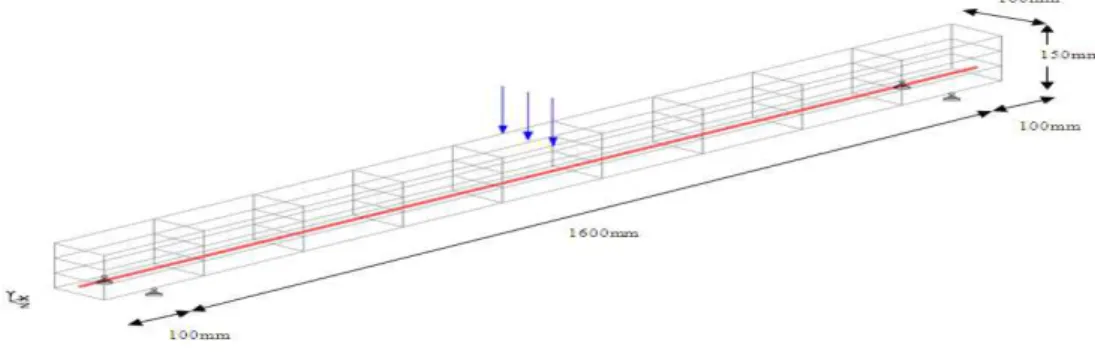
The beams were in the size of 100 mm in width by 150 mm in depth and 1600 mm in span. Beam 1 had one 12 mm reinforcing bar and beam 2 had two 12 mm reinforcement bars. The modu-lus of elasticity for steel reinforcement and concrete were Es= 210000 N/mm2 and Ec = 30800 N/mm2, respectively. In the present study, the beam was modelled by nine elements in the x direc-tion and three elements in the y direcdirec-tion (height of beam), as shown in Figure 11 below. A new truss-link element was used to model the bond-slip between the concrete and the steel. In the devel-oped code, apart from the Ottosen analytical yield criterion, two other yield criteria by Mohr-Coulomb and Drucker-Prager have been used for both beams.
Figure 11: Finite Element Model of Beam 1.
4.1.1 Results
The load-deflection behaviour of the developed model, together with the experimental results by Karihaloo (1990) and model by Ashour (1993), is shown in Figure 12. Two beams [namely, Beam 1 that is reinforced with one 12 mm diameter bar as in Figure 12(a), and Beam 2 with two 12 mm reinforcement bars in Figure 12(b) are presented.
A comparison of the results of the experimental and modelled reinforced concrete beams with non-linear models based on Ottosen, Mohr-Coulomb and Drucker-Prager yield criteria showed a reasonable agreement. The Ottosen model is the closest to that of Ashour’s (1993), but the experi-mental result is almost similar to those of the Mohr-Coulomb yield criteria.
4.2 Non-Linear Analysis of the FRP Strengthened Reinforced Concrete Beams
The developed computational programme is further verified in this section based on the experi-mental results of the reinforced concrete beams strengthened with FRP plates by Rahimi and Hutchinson (2001), and the numerical studies by Carlos et al. (2006). All three yield criteria, Ot-tosen, Mohr and Drucker-prager, are also verified. The interface of plate bending and brick element as discussed in Section 2.1.5 is used in this model.
described in Table 1, while the Type of external reinforcement and plate thickness are presented in Table 2. Additional details can be obtained from Rahimi and Hutchinson (2001).
(a) Beam 1
(b) Beam 2
Figure 12: Mid-Span Load-Deflection Curves a: beam 1, b: beam 2.
Concrete GFRP CFRP Epoxy Steel
Modulus of elasticity, E (GPa) 25 36 127 7 210
Yield strength, fy (MPa) -- -- -- -- 575
Tensile strength, ft (MPa) 3 1074 10532 25 --
Compressive strength, f‘c (MPa) 61 -- -- 70 --
Table 1: Properties of the materials used.
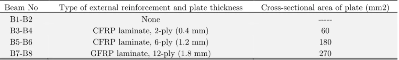
Beam No Type of external reinforcement and plate thickness Cross-sectional area of plate (mm2)
B1-B2 None ---
B3-B4 CFRP laminate, 2-ply (0.4 mm) 60
B5-B6 CFRP laminate, 6-ply (1.2 mm) 180
B7-B8 GFRP laminate, 12-ply (1.8 mm) 270
Table 2: The Geometric properties of external reinforcement in beams type B.
These beams are modelled using the three-dimensional finite element with internal reinforce-ment bars positioned at 140 mm apart in the width direction and 90 mm apart in the depth
direc-0 4 8 12 16
0 1 2 3 4 5
Load (
K
N)
Deflection (mm)
Mohr
Druker-Prager
Ottoson
Ashour (1993)
Karihaloo (1990)
0 5 10 15 20 25 30
0 1 2 3 4 5 6 7 8
Load (
K
N)
Deflection (mm)
Mohr
Druker-Pruger
Ottoson
Ashour (1993)
tion of the beam, as shown in Figure 13. The numbers of the different elements used in the physical model are also shown in the mentioned Figure 13(b).
(a)
(b)
Figure 13: (a) Beam Geometry, (b) Three-Dimensional Finite Element Mesh and Boundary Conditions.
The experimental results of type B beams by Rahimi and Hutchinson (2001), was used to verify the developed model. The developed model computed load-deflection curve of type B beams using three different yield criteria notated as Ottosen, Mohr and Drunker-Prager in Figures 14(a) to 14(d). The developed models of the reinforced concrete beams showed a reasonable agreement with those of the experimental results by Rahimi and Hutchinson (2001) and also the numerical studies by Carlos et al. (2006). The results for all the numerical studies are close enough for all the B1-B8 types, and these prove the ability of the model to capture the behaviour in linear and non-linear stages. In this study again, model that used Ottosen criteria, shows more deflection as compared to the other models, and this proves that the Ottosen model is a bit flexible compare to, Mohr and Drunker-Prager for concrete modelling.
Z
x
Y
(a) Beams B1-B2
(b) Beams B3-B4
(c)Beams B5-B6
(d)Beams B7-B8
Figure 14: Load vs Mid-Span deflection of Rahimi, Carlos and the present study using different Yield Criteria.
0 10 20 30 40
0 10 20 30 40 50 60
Deflection (mm) Rahimi (2001) Carlos (2006) Ottoson Mohr Drucker-Prager 0 10 20 30 40 50 60
0 10 20 30 40 50 60
Deflection (mm) Rahimi (2001) Carlos (2006) Ottoson Mohr Drucker-Prager -10 10 30 50 70
Ϭ ϭϬ ϮϬ ϯϬ ϰϬ
Load ( K N) Deflection (mm) Rahimi (2001) Carlos (2006) Ottoson Mohr Drucker-Prager 0 10 20 30 40 50 60
0 10 20 30 40 50 60
4.2.1 Slip Analysis Between Plate Layers and Concrete
Slip between the strengthening plates and concrete beams in the adhesive area are plotted in Fig-ures 15(a) and (b) for strengthened beams (B3-B4) and (B5-B6). As shown in these figFig-ures, there are distributions of the slip between the concrete and FRP plates to justify the shear stress occurred between the two. In the region of maximum shear, the beams have maximum slip and in the region of zero shear stress, zero slip is recorded. Almost the same distribution of slip is computed in elastic stage, regardless of the thickness and properties of the FRP material. This is because slip is related to the amount of shear stress in the region between the plate and concrete, but it is not related to the type of plates.
(a) Beam B3-B4
(b) Beam B5-B6
Figure 15: Slip (mm) between the FRP Plate and Concrete in the Adhesive Region of the Strengthened Beams.
4.3 Application to the Prefabricated Concrete Bridge Girder
Based on validation of the linear and non-linear finite element code for the reinforced concrete beam and the finite element interface developed code, the application of the developed model on the bridge girder is presented below.
Application of the developed code was made on a prefabricated highway bridge girder tested by Tianyu Xiang et al. (2005). The girder is a continuous reinforced concrete beam with four spans at 160 cm centre to centre. However, in the analysis of a prefabricated component, the girder was ana-lysed as simply supported. The arrangement of the reinforcement of each prefabricated girder is given in Table 3, while the basic material properties are presented in Table 4 and the geometrical configuration of the bridge and dimension of the girder is shown in Figure 16. This bridge was de-signed according to the Specifications for Design of Reinforced Concrete and Pre-stressed Concrete Highway Bridges and Culverts (JTJ023-85) of PR China.
Beam Length (mm)
Slip (mm)
Position As (mm2) H (mm)
Top layer 628 1121
Second layer 1607.68 1149.25
Third layer 1607.68 1183.75
Fourth layer 1607.68 1218.25
Fifth layer 1607.68 1252.75
Table 3: Reinforcement Arrangement.
Concrete Reinforcement
The characteristic compressive strength 17.5 MPa
The characteristic tensile strength 1.9 MPa 0.0033
The design compressive strength 11.6 MPa
The design tensile strength 1.24 MPa 272 MPa
The initial elastic modulus 28500 MPa 200000 MPa
The yield strain 0.002(ε0) 0.00136
The ultimate strain 0.0033 0.01
Table 4: Basic Material Properties.
Figure 16: Geometrical Configuration of the Bridge (all dimensions are in cm). Tianyu Xiang et al. (2005).
The total dead load is 17KN/m for each girder, and the design vehicle load is shown in Figure 17. By using the G-M method (Johnson, 1980), the vehicle distribution loads of all beams were cal-culated. For simplicity and safety, the design vehicle load for all the beams was adopted for the maximum transverse distribution load, and the corresponding vehicle load distribution coefficient was set at 0.313. The service limit state and ultimate limit state were also analyzed. For the service limit state, the load combination is given as D+V, where D and V are dead load and vehicle load, respectively. The load combination for the ultimate limit state is expressed as 1.2D+1.1V.
The prefabricated girder specimen was modelled with the three-dimensional finite element as shown in Figure 18. The total numbers of different elements used in the physical model is shown in the above-mentioned figure. The beam size is 1600 mm flange width by 1300 mm total depth. Meanwhile, the thickness of the web is 180 mm and the thickness of flange changes from 80 mm in the free end to 140 mm in the junction of the web and flange, with a clear distance between the supports of 19500 mm.
(a)
(b)
Figure 18: Three-Dimensional Geometry and Finite Element Mesh.
4.3.1 Results
In the ultimate limit state analysis, the variations of the vertical deflection, the relation between the maximum compressive stress of concrete and the maximum tensile stress of reinforcement bars, as well as the slip between bar and concrete in the fifth reinforcement layer and the moment at mid-span are plotted in Figures 19 to 22.
Figure 19: Mid-Span Moment-Deflection Behaviour of the Prefabricated Girder.
0 500 1000 1500 2000 2500
0 40 80 120 160
M
ome
nt
(K
N-m)
Deflection (mm)
Ottoson
Drucker-prager
Mohr
Tianyu (2005) Total No of Brick Elements 200
Figure 20: Response of the Maximum Steel Reinforcement Tensile Stress to Moment at Mid-Span.
Figure 21: Response of the Maximum Concrete Compressive Stress to Moment at Mid-Span.
Figure 22: Slip between the Maximum Stressed Reinforcement Bar (Fifth layer) and Concrete.
As shown in Figures 19 and 20, the variations of the vertical deflection, as well as the maximum tensile stress of reinforcement bars, are almost similar to the results for all the models, and this is sufficient to verify the ability of the proposed Ottosen four-parameter model. Figure 21 shows the results of the relationship between the maximum compressive stress of the concrete using three yield criteria have only a slight difference with that of Tianyu’s work (2005), as they are in a close range. Meanwhile, the slip results from Figure 22 show the ability of the Truss-link element to model the interfacial behaviour between the bars and the concrete. As expected, the model, using the Ottosen yield criterion, showed higher value of deflections, and therefore, using this model
0 500 1000 1500 2000 2500 3000
0 100 200 300 400 500 600
M
ome
nt
(K
N-m)
Tensile Stress (MPa)
Ottoson
Druker Pruger
Mohr
Tianyu (2005)
Ϭ ϱϬϬ ϭϬϬϬ ϭϱϬϬ ϮϬϬϬ ϮϱϬϬ
0 5 10 15 20
M
ome
nt
(K
N-m)
Stress (MPa)
Ottoson
Drucker-Prager
Mohr
Tianyu (2005)
-0,6 -0,4 -0,2 0 0,2 0,4 0,6
0 5000 10000 15000 20000
Slip (mm)
RC Girder Length (mm)
Ottoson
Druker-pruger
would yield a little higher value of slip as compared to the model that uses Mohr and Drucker-Prager yield criteria.
At service limit state, the stresses of reinforcement bars and the vertical deflection of girder un-der vehicle load at mid-span with three types of yield criteria were calculated and the results are tabulated in Table 5. The findings revealed that the results for stress in reinforcement bars under vehicle load for all layers are almost similar. The developed yield criterion using the Ottosen four-parameter model showed slightly more flexible results compared to the other yield criteria.
Ottosen Drucker-Prager Mohr –
Coulomb
Tianyu
(2005) JTJ023-85
Top layer(MPa) 298 218 233 216
Second layer(MPa) 310 231 242 223
Third layer(MPa) 316 241 258 233 261.3
Fourth layer(MPa) 340 254 271 242
Fifth layer(MPa) 368 274 292 251
Average(MPa) 326 243.6 259.2 233
Vertical deflection under vehicle load 30mm 22.6mm
Table 5: The Reinforcement Stress and Vertical Deflection at Mid-Span under Vehicle Load.
5 CONCLUSION
Based on the materials presented in this manuscript, the following conclusions can be drawn:
An interface element between two plate-bending elements has also been developed, and it is an attractive element with respect to its computer coding and computation time.
An interface element between two brick element and interface element between plate bending and brick elements has been developed, and this is an attractive element to model the rein-forced concrete girder bridges, as well as the interfacial behaviour between concrete and strengthening plate material.
Nonlinearities arising due to plastic yielding of concrete considered to predict the inelastic re-sponse of RC components.
The non-linear plastic model for concrete has been identified and its computational procedure has also been included.
A generalised computational algorithm to generate the above-mentioned conventional isopar-ametric elements and interface elements has been developed and presented.
A comprehensive computational procedure to trace the response of the reinforced concrete structure through its elastic and inelastic response has been discussed and implemented. Necessary subroutines to be implemented in the host programme in the FORTRAN language
has been developed and integrated with the host finite element programmes. The proposed algorithm has been codified and a computer code has also been developed.
rein-forcement layer and the moment at mid-span, have been computed as shown in Figures 5.7 to 5.10. These results have a very close agreement with those of the earlier study by Tianyu (2005). The results also show the ability of the developed code to predict the structural be-haviour of the RC girder bridge.
References
Abdel Baky, H., Ebead, U.A., Neale, K.W., (2007). Flexural and interfacial behavior of frp-strengthened reinforced concrete beams. Journal of Composites for Construction 11(6): 629–639.
Ahmad, M., Bangash, Y., (1987). A three-dimensional bond analysis using finite element. computer and structure 25: 281-296.
Ali Zokaei, A., Cesar C., Soheil, N., (2014). Finite element modeling of slab–foundation interaction on rigid pave-ment applications. Computers and Geotechnics 62: 118–127.
Ashour, A.F., Morley, C.T., (1993). Three-dimensional nonlinear finite element modeling of reinforced concrete struc-tures. Finite Elements in Analysis and Design 15(1): 43-55.
Carlos, A.C., Maria, M.L., (2006). Sensitivity analysis of reinforced concrete beams strengthened with FRP lami-nates. Cement & Concrete Composites 28(1): 102–114.
CEB-FIP model code 90. (1993). CEB-FIP Comitè Euro-International du Bèton, London.
Chansawat, k., Solomon C.S.Y., Thomas H.M., (2006). Nonlinear finite element analysis of a frp-strengthened rein-forced concrete bridge. Journal of Bridge Engineering 11(1): 21-32.
Ebead, U., Marzouk, H., (2004). Fiber-reinforced polymer strengthening of two-way slabs. ACI Structural Journal 101(5):650–659.
Eligehausen, R., Popov, E.P., Bertero, V.V., (1983). Local bond stress-slip relationship of deformed bars under gen-eralized excitations. Earthquake Engineering Center, University of California, Berkeley. Report No.; UCBEERC-83/23.
Elsayed, W., Ebead, U., Kenneth W., (2007). Neale interfacial behavior and debonding failures in frp-strengthened concrete slabs. Journal of Composites for Construction 11(6): 619-628.
Harajli, M.H., Hout, M., Jalkh, W., (1995). Local bond stress–slip behaviour of reinforcing bars embedded in plain and fiber concrete. ACI Materials Journal 92(4): 343–354.
Hu, H.T., Lin F.M., Jan, Y.Y., (2004). Nonlinear finite element analysis of reinforced concrete beams strengthened by fibre-reinforced plastic. Composite Structures 63: 271–281.
Jialai, W., Chao, Z., (2010). A three-parameter elastic foundation model for interface stresses in curved beams exter-nally strengthened by a thin FRP plate. International Journal of Solids and Structures 47: 998–1006.
Johnson Victor, D. (2004). Essentials of bridge engineering. New Delhi: Oxford and IBH Publishing Co.
Karihaloo, B.L. (1990). Failure modes of longitudinally reinforced beams, Int. Workshop on the Application of Frac-ture Mechanics to Reinforced Concrete, Italy, 523-546.
Khelifa, M., Auchet, S., Méausoone, p.J., Celzard, A., (2015). Finite element analysis of flexural strengthening of timber beams with Carbon Fibre-Reinforced Polymers. Engineering Structures 101: 364–375.
Kohnehpooshi, O. (2012). Nonlinear three dimensional finite elements for composite concrete beams, Ph.D. Thesis, University Putra Malaysia, Malaysia
Kohnehpooshi, O., Noorzaei, J., Jaafar, M. S., Raizal Saifulnaz M.R., (2011). A new 3D interface element for three dimensional finite element analysis of FRP strengthened RC beams. Interaction and Multiscale Mechanics 4(4): 257-271.
Kohnehpooshi, O., Noorzaei, J., Jaafar, M. S., Raizal Saifulnaz, M. R., Abdulrazeg, A. A., (2010b). A 3d interface element for plate bending elements. World Engineering Congress, 2nd–5th August. Kuching, Sarawak, Malaysia. Lu , X. Z., Jiang, J. J., Teng, J. G., Ye, L. P., (2006). Finite element simulation of debonding in FRP-to-concrete bonded joints. Construction and Building Materials 20: 412–424.
Lu, X. Z., Teng, J. G., Ye, L. P., Jiang, J. J., (2005). Bond–slip models for FRP sheets/plates bonded to concrete. Engineering Structures 27(6): 920–937.
Lundquist, J., Nordin, H., Täljsten, B., Olafsson, T., (2005). Numerical analysis of concrete beams strengthened with CFRP – a study of anchorage lengths. In: FRP in construction, Proceeding of the international symposium of bond behaviour of FRP in structures 247–54.
Manzoli, O.L., Gamino, A.L., Rodrigues, E.A., Claro, G.K.S., (2012). Modeling of interfaces in two-dimensional problems using solid finite elements with high aspect ratio. Computers and Structures 94-95:70-82.
Milani, G. (2010). FE limit analysis model for multi-layer masonry structures reinforced with FRP strips. Interna-tional Journal of Mechanical Sciences doi:10.1016/ j.ijmecsci. 2010.01.004.
Niu, H. D., Wu, Z. S., (2006). Effects of frp-concrete interface bond properties on the performance of rc beams strengthened in flexure with externally bonded frp sheets. Journal of Materials in Civil Engineering 18(5): 723–731. Ottosen, N.S. (1977). A failure criterion for concrete. Journal of the Engineering Mechanics, ASCE. 103(4): 527-535. Rahimi, H., Hutchinson, A., (2001). Concrete beams strengthened with externally bonded FRP plates. Journal of Composites for Construction 5(1): 44-56.
Rodrigues E.A., Manzoli O.L., Bitencourt Jr L.A.G., Prazeres P.G.C., Bittencourt T.N., (2015). Failure behavior modeling of slender reinforced concrete columns subjected to eccentric load. Latin American Journal of Solids and Structures 12: 520-541.
Rodrigues, E.A., Manzoli, O.L., Bitencourt Jr L.A.G., Bittencourt T.N.,(2016). 2D mesoscale model for concrete based on the use of interface element with a high aspect ratio. International Journal of Solids and Structures 94–95: 112–124.
Santhakumar, R., Chandrasekaran, E., (2004). Analysis of retrofitted reinforced concrete shear beams using carbon fibre composite. Electronic Journal of Structural Engineering 4(1):66–74.
Sayed-Ahmed, E.Y., Bakay, R., Shrive, N.G., (2009). Bond strength of frp laminates to concrete: state-of-the-art review. Electronic Journal of Structural Engineering 9(1): 45-61.
Song, H.W., You, D.W., Byun, K.J., Koichi, M., (2002). Finite element failure analysis of reinforced concrete T-girder Bridges. Engineering Structures 24(2): 151–162.
Sulata, K. ( 2007). Behaviour of rcc t-beam bridges with cross diaphragms in nonlinear range. Journal of Bridge Engineering 12(5): 560-569.
Tianyu, X., Yuqiang, T., Renda, Z., (2005). A general and versatile nonlinear analysis programme for concrete bridge structure. Advances in Engineering Software 36(10): 681–690.
Tong, G., Zheheng, C., Tie, L., Dazhang, H., (2016). Time-dependent reliability of strengthened PSC box-girder bridge using phased and incremental static analyses. Engineering Structures 117: 358–371.
Transport Ministry of PR China, Specifications for design of reinforced and prestressed concrete highway bridges and culverts, JTJ023-85.
Viladkar, M. N., Godbole, P. N., Noorzai, J., (1994). Interactive analysis of a space frame-raft-soil system considering soil nonlinearity. Computers and Structures 51(4): 343–356.