LINK PERFORMANCE EVALUATION FOR EGPRS WITH MULTIPLE ANTENNAS
W. C. Freitas Jr1, F. R. P. Cavalcanti1, C. C. Cavalcante2, D. Zanatta Filho2and A. L. F. de Almeida1
1
GTEL-UFC: Wireless Telecom Research Group, Federal University of Cear´a, Fortaleza, Brazil URL:www.gtel.ufc.br
{walter,rod,andre}@gtel.ufc.br
2
DSPCom: Digital Signal Processing for Comm. Lab., State University of Campinas, Campinas, Brazil URL:www.decom.fee.unicamp.br/ dspcom.ufc.br
{charles,daniloz}@decom.fee.unicamp.br
Abstract - Transmission diversity schemes have recently
emerged in wireless systems as an attractive solution in order to mitigate fading effects. Space-time block codes (STBC) with two antennas can provide similar order diversity as maximal-ratio receiver combining (MMRC). In this paper transmit diversity scheme using STBC with two and four an-tennas is applied for the EDGE/EGPRS system and its results are evaluated in a interference-limited scenario. We jointly compare this strategy of multiple antennas with incremental redundancy (IR), a technique for link quality control (LQC) in EDGE.
Keywords - EDGE, Space Time Block Codes, Incremental
Redundancy
I. INTRODUCTION
The enhanced general packet radio service of EDGE (EGPRS) combines multilevel modulation and an efficient link quality control in order to reach the high data rates de-manded by third generation (3G) systems. With those char-acteristics EGPRS arises as a natural evolutionary path for two TDMA-based second generation (2G) systems, namely
GSM and IS-136. In the physical layer of EGPRS there
are nine modulation and coding schemes (MCSs),
MCS-1 through MCS-9. Four of them use GMSK modulation
(MCS-1 through MCS-4) and five use the 8-PSK multilevel modulation (MCS-5 through MCS-9). As link quality con-trol strategies, EGPRS uses link adaptation (LA) and incre-mental redundancy separately or jointly. Through this dy-namic adaptation in agreement with the link quality, one may choose between transmission rates and protection to maxi-mize throughput.
The fading effect is one of the most important drawback factors of the maximum data rates reached by wireless com-munication systems. To mitigate fading some diversity strate-gies are usually provided, among which we can highlight: time, frequency and space diversity. Currently, in 2G net-works, the most common strategies used for receive diversity include: space diversity - multiple antennas in the base sta-tions are employed to provide receive diversity; time diversity channel coding with interleaving; and frequency diversity -frequency hopping (FH) for TDMA systems and RAKE re-ceiver for CDMA systems.
As internet traffic is expected to be asymmetric, with higher data rates on the forward link, the issue of transmit diversity becomes important. This importance arises because the link quality control of EGPRS will translate into throughput gain any gain perceived at the link-level, such as a diversity gain. Some possibilities of transmit diversity are then investigated in this work and their gains evaluated.
In [1], Alamouti has proposed a simple transmission diver-sity scheme using space-time block codes (STBC) with two antennas. The obtained diversity order is similar to apply-ing a maximal-ratio receiver combinapply-ing (MMRC) with two antennas at the receiver. This scheme requires no bandwidth expansion, as redundancy is applied in space across multi-ple antennas. In [2], an extension to a scheme similar to Alamouti’s STBC for more than two antennas in transmis-sion is proposed using the Theory of Orthogonal Design [3]. Alamouti’s scheme is indicated for flat fading channels, there-fore without intersymbol interference (ISI). A generalization for channels with ISI is given in [4].
In this work we study the performance of multiple antennas applied in the context of the EDGE system. The structure uses STBC to provide transmission diversity with two and four an-tennas. We also evaluate the performance of STBC with a more efficient LQC strategy such as IR. Firstly, in section II e describe the space-time codes and the techniques involved to provide transmit diversity. In section III the EDGE/EGPRS simulator model is presented. After that, in section IV the LQC strategy used in EDGE, incremental redundancy (IR), is explained. In section V the simulation results are presented and discussed. Finally in section VI we establish our conclu-sions.
II. SPACETIMECODES
Space-time codes (STC) use channel coding techniques combined with multiple transmit antennas to increase data rates over wireless channels. STC introduces temporal and spatial correlation into signals transmitted from different an-tennas, in order to provide diversity at the receiver, and coding gain over an uncoded system without sacrificing bandwidth [1].
when the number of antennas is fixed, the decoding complex-ity of STTC (measured by the number of trellis states at the decoder) increases exponentially as a function of the diversity level and transmission rate. In addressing the issue of decod-ing complexity, Alamouti [1] discovered a remarkable STBC scheme for transmission with two antennas [5]. In this work the simulation results will only consider STBC.
A. Alamouti’s Space Time Block Codes (STBC)
Alamouti proposed a simple scheme of transmission
diver-sity with two transmit antennas in which two symbolss1and
s2 are simultaneously transmitted by different antennas at a
given symbol period, where s1 is the signal transmitted by
antenna one ands2is the signal transmitted by antenna two.
In the next symbol period, antenna one transmits−s∗2 and
antenna two transmitss∗
1. It is assumed that the channel is
constant during two periods of consecutive symbols. Con-sidering this space-time coding, the received symbols in two consecutive symbol periods are:
· r1 r2 ¸ = ·
s1 s2
−s∗ 2 s∗1
¸ · · h1 h2 ¸ + · n1 n2 ¸ (1)
where the channels samplesh1andh2may be modelled by a
complex multiplicative distortion andn1andn2are gaussian
noise samples. This representation can be reorganized in a similar manner as:
· r1 r∗ 2 ¸ = ·
h1 h2
h∗ 2 −h∗1
¸ · · s1 s2 ¸ + · n1 n∗ 2 ¸ (2)
In a matrix equivalent form we have:r=Hs+n.
For detection, Alamouti proposes the multiplication of the
received signal vectorrby matrixHH
. Therefore the symbol
estimated can be obtained byˆs=HH
·r=HH
·Hs+HH ·n.
It can be noted thatHis orthogonal andHH
is the matched
filter, so: HH
·H = (|h1|2
+|h2| 2
)·Iandˆsis the vector
of matched filter output. Those observations imply that the
symbolss1 ands2can be recovered from the matched filter
output.
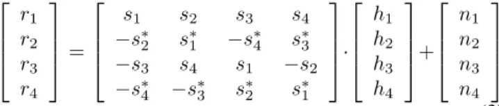
Tarokh, in [2], achieved, through orthogonal designs, sim-plicity similar to Alamouti’s STBC for more than two anten-nas for transmission. Using four antenanten-nas the received sym-bols, in four consecutive symbol periods are:
r1 r2 r3 r4 =
s1 s2 s3 s4
−s∗
2 s∗1 −s∗4 s∗3
−s3 s4 s1 −s2
−s∗
4 −s∗3 s∗2 s∗1
· h1 h2 h3 h4 + n1 n2 n3 n4 (3) The same detection strategy used for two antennas can be used in this case.
This Alamouti’s scheme is indicated for channels without intersymbol interference (ISI), but due to the nature of the mobile radio channel, transmitter, receiver, pulse shape and modulations present in the EDGE, ISI may be present. In
Table 1
Modulation and Coding Schemes in EGPRS.
MCS User Code Header Blocks
Rate Rate Code per
[Kbps] Rate 20ms
9(8-PSK) 59.2 1.0 0.36 2
8(8-PSK) 54.4 0.92 0.36 2
7(8-PSK) 44.8 0.76 0.36 2
6(8-PSK) 29.6 0.49 1/3 1
5(8-PSK) 22.4 0.37 1/3 1
4(GMSK) 17.6 1.0 0.51 1
3(GMSK) 14.8 0.85 0.51 1
2(GMSK) 11.2 0.66 0.51 1
1(GMSK) 8.8 0.53 0.51 1
order to deal with this drawback some changes in the STBC rule were made, as it will be shown in the next section.
B. STBC for Channels with Intersymbol Interference
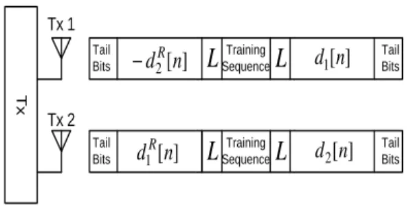
Lindskog and Paulraj in [4] extended the considerations made by Alamouti from symbol-wise to block-wise in order to treat channels with ISI. In this scheme a block of symbols
d[n]is divided in two sub-blocksd1[n]andd2[n]as well as
the transmission frame. In the first half of the frame,d1[n]
is transmitted by antenna one and d2[n]by antenna two. In
the second half of the frame, d2[n]time reversed, complex
conjugated1 and negated is transmitted by antenna one and
d1[n] time reversed and complex conjugated from antenna
two. This can be represented by:
· r1 rR 2 ¸ = ·
h1 h2
hR
2 −h
R 1 ¸ ∗ · d1 d2 ¸ + · n1 nR 2 ¸ (4)
In this case the ordinary multiplication is replaced by convo-lution. For detection, the same strategy used for the previous scheme can be applied here.
58 symbols 58 symbols Tail Bits Tail Bits Training Sequence
Fig. 1. Normal burst GSM.
In EDGE/EGPRS each user payload (RLC radio block) is interleaved over two (MCS-1 up to MCS-6) or four bursts (MCS-7 up to MCS-9), and each burst contains 116 user data symbols (modulated with either GMSK or 8-PSK, see Table 1), 26 training symbols in the middle and 3 tail bits in the ex-tremities. In [6], a new burst format scheme using two trans-mit antennas and compatible with the GSM burst format is proposed.
T
x
Tx 1
Tx 2
Training Sequence Tail
Bits
Tail Bits
]
[
2
n
d
]
[
1
n
d
RL
L
Training Sequence Tail
Bits
Tail Bits
]
[
1
n
d
]
[
2
n
d
R−
L
L
Fig. 2. New burst format.
Due to ISI in the downlink channels, some “edge effects” are introduced in the transmitted signals, and these effects need to be considered in the design of the new burst format.
LetLdenote the maximum delay of the two-downlink
chan-nels [6].
In Figs 1 and 2, two burst formats are described. In the Fig. 1 the normal GSM burst format is shown, while in Fig. 2 the new burst format suitable to two transmit antennas is presented.
In the new format, the block contains 116 data symbols,
{d[n]115
n=0} , which are divided in two sub-blocks and now
transmitted in two bursts. The sub-blocks are defined as fol-low:
d1[n] =d[n]; n= 0, ...,57
d2[n] =d[n]; n= 58, ...,115 (5)
III. EDGE/EGPRS LINKLEVELSIMULATOR
A EDGE/EGPRS link level simulator has been con-structed based on 3GPP specifications. The physical layer of EGPRS is simulated including: channel encoder, interleav-ing, burst mapping modulator, pulse shapinterleav-ing, channel mod-elling, equalizer, de-interleaving and decoder. The simula-tor is divided in two parts: inner core and outer core. The outer core encompasses the functions at the radio link control (RLC) block level, while the inner core is responsible for the burst level. In this paper the outer core part is implemented following the detailed 3GPP specifications [7]. On the other hand, some simplifications are assumed for the inner core as discussed later.
The Jakes’ fading model is used for generating the chan-nel response. Its time variation and correlation depends on the mobile velocity. For the frequency hopping (FH) case in-dependent channel samples are generated for each burst. For no frequency hopping (NoFH), the degree of channel corre-lation, from burst to burst, depends on the velocity. For the interference-limited scenario, one time-aligned interferer is assumed. The same assumptions regarding fading, modula-tion and velocity made for the desired user are extended for the interferer. The severity of the Doppler spread is controlled according to the selected mobility conditions.
The basic unit of time in the simulator is an RLC radio block; each RLC radio block is referred to as iteration. As
in EGPRS specifications, the header and data are coded sep-arately. At each iteration the first task of the simulator is to separate the RLC radio block in two parts: header and data blocks. After that, each part is coded and punctured sepa-rately in agreement with [7] and the interleaving and map-ping of burst is made for subsequent transmissions in the air interface.
IV. INCREMENTALREDUNDANCY
As link quality control strategies, the EGPRS can use link adaptation (LA) and incremental redundancy (IR) separately or together. Each MCS has up to three puncturing patterns,
P1,P2andP3, with each representing the same RLC radio
block, which can be used to decode an RLC radio block or can be combined together to provide coding gain (IR mode). In [8] a description of LQC methods is made.
Using IR, the data block coded is divided in smaller sub-blocks of the same size, through the puncturing process. Ini-tially, one sub-block containing little or no redundancy is transmitted reaching thus one high rate of transmission since the rate coding is sufficiently high, generally close to 1. If the data block is not received correctly more redundancy is sent in the next retransmission with a different puncturing pattern. The erroneous blocks are stored, and combined with the sub-sequent blocks until the successful decoding of the data block transmitted.
V. PERFORMANCERESULTS
We compare the performance of a single antenna and STBC with two and four uncorrelated antennas for MCS-1 and MCS-4. Some simplifications on the inner physical layer are assumed. The BPSK modulation scheme replaces GMSK with perfect phase recovery in the receiver. Flat fading is also assumed and can be considered a good approximation for the typical urban (TU) channel [9]. We are also assuming per-fect channel estimation in the receiver. When a more realistic channel estimation is considered, e.g. based on the training sequence, some decrease in the performance is expected.
With perfect timing at the receiver and synchronized in-terference, no further considerations about pulse shaping are essential at this moment. We use the burst format displayed in
Fig. 3 when considering two transmit antennas withL= 0.
The STBC scheme utilizing four transmit antennas is sim-ilar to scheme for two antennas, in this case the data blocks is divided in four sub-blocks d1[n], d2[n],d3[n] andd4[n].
The transmit matrix is show in 3 when using four antennas. A RLC radio block is mapped in four bursts when transmitting with four antennas following the fig. 3.
Tx
Tx 3 Tx 2 Tx 1
Tx 4
Training Sequence Tail
Bits
Tail Bits L L-d2[n]d1[n] ]
[
3n
-d ] [
4n
-d
Training Sequence Tail
Bits
Tail Bits L L d1[n] d2[n]
] [
4n
d ] [
3n
-d
Training Sequence Tail
Bits
Tail Bits
L L
] [
2n
d d1[n] -d4[n]d3[n]
Training Sequence Tail
Bits
Tail Bits
L L
] [
1n
d -d2[n] d3[n] d4[n] *
*
*
* *
* * *
Fig. 3. New burst format transmitting with four antennas.
MCS can be found from the BLER values by using the fol-lowing rule:
Throughput = (1−BLER)·Rmax (6)
whereRmaxis the user data rate for a given modulation and
coding scheme, e.g. 8.8 Kbps for MCS-1, see Table 1. For results the BLER is measured over 3000 RLC blocks with two and four transmit antennas in the downlink. As LQC the use of IR is also evaluated. It is assumed that the total transmit power for STBC is the same as the one for a single antenna. A block is said to be erroneous, if one or more the following events occurs:
• Cyclic redundancy code fail for the header;
• Cyclic redundancy code fail for the RLC data block.
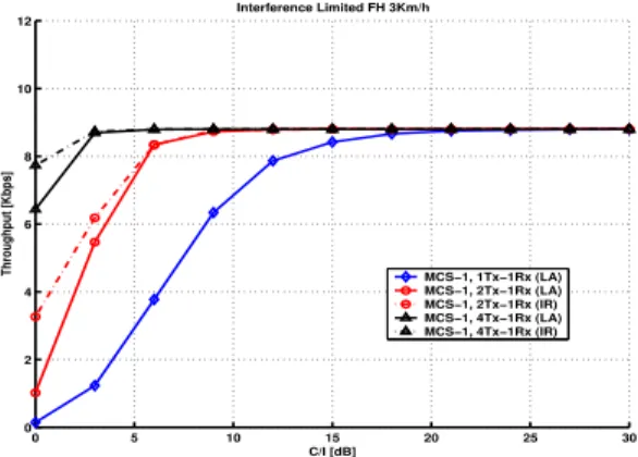
Figs. 4 to 7 show comparative results using STBC with two and four antennas where the use of IR can or cannot be used. On Fig. 4 it is shown results for MCS-1 in a sce-nario limited by interference when FH is used in low mobility (3 Km/h). For high mobility (100 Km/h) similar results are achieved since MCS-1 is well protected. Fig. 6 show result for NoFH in high mobility. Comparing Figs. 4 and 6 we see that transmit diversity provides better gain when FH is used. This can be explained by the high protection found in MCS-1. In case of MCS-4, Figs. 5 and 7, the use of FH represent a loss of performance. This can be explained by not perceived temporal diversity for less protected MCS when FH is used, with FH, one single burst experiencing a poor channel state may be enough to produce an erroneous block. Use of IR enhance the performance throughput for low quality channel conditions.
Tables 2 to 5 summarize the throughput gains relative some reference scenarios. Transmit diversity is an important tech-nique to mitigate the fading effects specially in less protected MCS. This can be proved by observation of these table re-sults for low SIR (6dB) where the fading effects are more pronounced. The better performance is achieved for less pro-tected MCSs for most of scenarios, especially when the refer-ence scenario considered is (1Tx-1Rx, FH 3Km/h), as shown in Table 3.
0 5 10 15 20 25 30
0 2 4 6 8 10 12
C/I [dB]
Throughput [Kbps]
Interference Limited FH 3Km/h
MCS−1, 1Tx−1Rx (LA) MCS−1, 2Tx−1Rx (LA) MCS−1, 2Tx−1Rx (IR) MCS−1, 4Tx−1Rx (LA) MCS−1, 4Tx−1Rx (IR)
Fig. 4. Throughput performance using STBC with transmit
antennas.
0 5 10 15 20 25 30
0 2 4 6 8 10 12 14 16 18
C/I [dB]
Throughput [Kbps]
Interference Limited FH 3Km/h
MCS−4, 1Tx−1Rx (LA) MCS−4, 2Tx−1Rx (LA) MCS−4, 2Tx−1Rx (IR) MCS−4, 4Tx−1Rx (LA) MCS−4, 4Tx−1Rx (IR)
Fig. 5. Throughput performance using STBC with transmit
antennas.
VI. CONCLUSION
The achieved results states that STBC could combat the fading effects, thus offering increased throughput when two transmit antennas are employed. As a general rule, trans-mit diversity provides higher relative gains for less protected MCSs under bad channel conditions. Further improvement in performance can be obtained by using incremental redun-dancy together with transmit diversity.
For the use of STBC some changes in EDGE/EGPRS stan-dards are needed. Among these changes we can highlight the required two different training sequences transmitted by the two antennas for channel estimation in the receiver and STBC encoder.
The results in this paper also show that most of the bene-fit gained from transmit diversity is already realized with two antennas, and that four transmit antennas may not ne neces-sary.
0 5 10 15 20 25 30 0
2 4 6 8 10 12
C/I [dB]
Throughput [Kbps]
Interference Limited NoFH 100Km/h
MCS−4, 1Tx−1Rx (LA) MCS−4, 2Tx−1Rx (LA) MCS−4, 2Tx−1Rx (IR) MCS−4, 4Tx−1Rx (LA) MCS−4, 4Tx−1Rx (IR)
Fig. 6. Throughput performance using STBC with transmit
antennas.
0 5 10 15 20 25 30
0 2 4 6 8 10 12 14 16 18
C/I [dB]
Throughput [Kbps]
Interference Limited FH 3Km/h
MCS−4, 1Tx−1Rx (LA) MCS−4, 2Tx−1Rx (LA) MCS−4, 2Tx−1Rx (IR) MCS−4, 4Tx−1Rx (LA) MCS−4, 4Tx−1Rx (IR)
Fig. 7. Throughput performance using STBC with transmit
antennas.
Table 2
Throughput gains [%] for MCS-1 (relative to 1Tx-1Rx, FH) at 3Km/h
FH 2Tx-1Rx FH 4Tx-1Rx
SIR[dB] SIR[dB]
6 15 6 15
MCS1(LA) 121.10 4.47 132.94 4.47
MCS1(IR) 121.10 4.47 132.94 4.47
Table 3
Throughput gains [%] for MCS-4 (relative to 1Tx-1Rx, FH) at 3Km/h
FH 2Tx-1Rx FH 4Tx-1Rx
SIR[dB] SIR[dB]
6 15 6 15
MCS4(LA) 151.92 51.81 178.33 66.29
MCS4(IR) 1280.77 57.36 3510.36 66.46
ACKNOWLEDGEMENTS
This work is supported by Ericsson Research-Brazilian Branch under the ERBB/UNI.33 Technical Cooperation
Con-Table 4
Throughput gains [%] for MCS-1 (relative to 1Tx-1Rx, NoFH) at 100Km/h
NoFH 2Tx-1Rx NoFH 4Tx-1Rx
SIR[dB] SIR[dB]
6 15 6 15
MCS1(LA) 65.36 6.46 81.23 6.64
MCS1(IR) 65.36 6.46 81.23 6.64
Table 5
Throughput gains [%] for MCS-4 (relative to 1Tx-1Rx, NoFH) at 100Km/h
NoFH 2Tx-1Rx NoFH 4Tx-1Rx
SIR[dB] SIR[dB]
6 15 6 15
MCS4(LA) 325.54 52.11 612.23 55.02
MCS4(IR) 411.07 52.38 785.74 55.02
tract.
REFERENCES
[1] S. Alamouti, ”A Simple Transmit Diversity Technique
for Wireless Communications”,IEEE Journal of Selected
Areas in Communications, vol. 16, no. 8, pp. 1451-1458, Oct.1998.
[2] V. Tarokh, H. Jafarkhani and A. R. Calderbank,
”Space-Time Block Codes from Orthogonal Designs”, IEEE
Transactions on Information Theory, vol. 45, no. 5, pp. 1456-1467, July 1999.
[3] A. V. Geramita and J. Seberry, ”Orthogonal Designs,
Quadratic Forms and Hadamard Matrices”, Lectures
Notes in Pure and Applied Mathematics, vol. 43. New York and Basel: Marcel Dekker, 1979.
[4] E. Lindskog, A. Paulraj, ”A Transmit Diversity Scheme
for Channels with Intersymbol Interference”, inProc. Int.
Conf. Communications, New Orleans, LA, pp. 307 - 311, June 2000.
[5] A. F. Naguib, N. Seshadri and A. R. Calderbank.,
”In-creasing Data Rate over Wireless Channels”,IEEE Signal
Processing Magazine, May 2000 pp.76-92.
[6] K. Zangi, D. Hui and J. F. Cheng, ”Physical-Layer Issues for Deploying Transmit Diversity in GPRS/EGPRS
Net-works”, inIEEE VTC Fall 2001, Atlantic City, NJ, USA.
[7] 3GPP, ”Channel Coding”,TS 45.003, v5.1.0, July 2001.
[8] S. Eriksson et al., ”Comparison of Link Quality Control
Strategies for Packet Data Services in EDGE”, in
Pro-ceedings of IEEE VTC’99.
[9] H. Olofsson, M. J. Almgren, C. Johansson, M. Hook and F. Kronestedt, ”Improved Interface between Link Level and System Level Simulations Applied to GSM”,
![Fig. 6. Throughput performance using STBC with transmit antennas. 0 5 10 15 20 25 30024681012141618 C/I [dB]Throughput [Kbps] Interference Limited FH 3Km/h MCS−4, 1Tx−1Rx (LA)MCS−4, 2Tx−1Rx (LA)MCS−4, 2Tx−1Rx (IR)MCS−4, 4Tx−1Rx (LA)MCS−4, 4Tx−1Rx (IR)](https://thumb-eu.123doks.com/thumbv2/123dok_br/15305179.549242/5.918.98.392.108.318/throughput-performance-using-transmit-antennas-throughput-interference-limited.webp)
