Miguel Carvalho Pires
Licenciado em Engenharia InformáticaIncremental Compilation and Deployment for
OutSystems Platform
Dissertação para obtenção do Grau de Mestre em Engenharia Informática
Orientador : João Costa Seco, Professor Auxiliar, FCT/UNL
Co-orientador : Lúcio Ferrão, Principal Software Engineer, OutSystems
Júri:
Presidente: Prof. José Augusto Legatheaux Martins Arguente: Prof. Salvador Pinto Abreu
iii
Incremental Compilation and Deployment for OutSystems Platform
Copyright cMiguel Carvalho Pires, Faculdade de Ciências e Tecnologia, Universidade Nova de Lisboa
Acknowledgements
I could not carry such hard but rewarding journey until the end if it was not the support and the valuable contribution of some people. I hope I did not forget anyone.
A want to express my sincere gratitude for my supervisors Lucio Ferrão, from Out-Systems, and João Costa Seco, from Faculdade de Ciências e Tecnologia de Lisboa (FCT). Thanks for your guidance. Thanks for the patience and the interest with which you helped me to communicate better and to be more critical with my own work. Thanks for your reviewing and critical observations.
I want to thank Faculdade de Ciências e Tecnologia de Lisboa (FCT) for giving me the opportunity of work in such intellectually engaging environment that isOutSystems R&D team, and for the monetary support.
A very special thanks to Ricardo Soeiro, the team leader of the pipeline team. I thank you for your guidance and valuable support. I thank you for all the insightful discussions we had, which helped me to make sense of the problem I was tackling. Without you this work would not have been possible.
Finally, I want to thank my friends and family.
To my father, who did everything that was at his reach to help me being a better prepared person. To my stepmother and my grandmother, for your support and love.
To my friends, Nuno Costa, Nuno Cruz, Hugo Cabrita, and Daniel Santos. Thank you all, for your companionship and support, for raising my spirits at those moments when things seemed more deary and daunting.
Abstract
OutSystems Platform is used to develop, deploy, and maintain enterprise web an mobile web applications. Applications are developed through a visual domain specific language, in an integrated development environment, and compiled to a standard stack of web technologies. In the platform’s core, there is a compiler and a deployment service that transform the visual model into a running web application.
As applications grow, compilation and deployment times increase as well, impact-ing the developer’s productivity. In the previous model, a full application was the only compilation and deployment unit. When the developer published an application, even if he only changed a very small aspect of it, the application would be fully compiled and deployed.
Our goal is to reduce compilation and deployment times for the most common use case, in which the developer performs small changes to an application before compiling and deploying it. We modified the OutSystems Platform to support a new incremen-tal compilation and deployment model that reuses previous computations as much as possible in order to improve performance.
In our approach, the full application is broken down into smaller compilation and deployment units, increasing what can be cached and reused. We also observed that this finer model would benefit from a parallel execution model. Hereby, we created a task driven Scheduler that executes compilation and deployment tasks in parallel. Our benchmarks show a substantial improvement of the compilation and deployment process times for the aforementioned development scenario.
Resumo
A plataforma OutSystems é usada para o desenvolvimento,deployinge manutenção de applicaçõeswebempresariais e móveis. As aplicações são desenvolvidas através de uma linguagem visual de domínio específico, em um ambiente integrado de desenvol-vimento, e são compiladas numa pilha convencional de tecnologiasweb. Na plataforma, existe um compilador e um serviço dedeploymentque são responáveis pela transformação do modelo visual numa applicaçãowebfuncional.
Com o crescimento de uma aplicação, os seus tempo de compilação edeployment tam-bém aumentam, o que afecta a produtividade do programador. No modelo anterior, a aplicação era a única unidade de compilação e deployment. Quando uma aplicação era publicada, ainda que o programador tivesse realizado uma alteração de muito pequena dimensão, a aplicação seria sujeita a um processo completo de compilação edeployment.
O nosso objectivo é reduzir os tempos de compilação edeploymentpara o caso de uso mais comum, em que o programador efectua pequenas mudanças numa aplicação antes despoletar a sua compilação edeployment. Nós modificámos a plataforma OutSystems para suportar um novo modelo de compilação e deployment incremental que reutiliza resultados de publicações antecedentes, de forma a reduzir processamentos redundantes e consequentementemente os tempos de espera.
Na nossa abordagem, a modelo de aplicação é partido em unidades de compilação e deployment mais pequenas, aumentando, assim, o que pode ser aproveitado por pu-blicações posteriores. Observou-se, também, que este modelo mais fino benificiaria de um modelo de execução paralelo. Nesse sentido, criou-se uma unidade de execução de tarefas que escalona as tarefas de compilação edeploymenttirando partido paralelismo. As nossas métricas revelam uma redução substancial dos tempos de compilação e deploy-ment, para os cenários acima mencionados.
List of Figures
2.1 Vesta’s architecture . . . 9
2.2 A functional self-adjusting program and the respective dynamic dependency graph 12 3.1 A typical development session on Service Studio. . . 16
3.2 The definition of an action . . . 17
3.3 Entity’s attributes and actions . . . 18
3.4 Entity’s meta-information . . . 18
3.5 Developer iterating a Web Screen in Service Studio . . . 19
3.6 A Web Block that modularizes the user context panel . . . 19
3.7 A Structure . . . 20
3.8 Developer’s Workflow . . . 21
3.9 ServiceStudio notifying the user to errors in the model . . . 21
3.10 Top elements most changed between consecutive versions . . . 22
3.11 OutSystems Platform Server’s architecture . . . 23
3.12 An example of the structure of a deployed application. . . 24
3.13 Publication’s phases . . . 25
3.14 Publication’s Protocol . . . 26
3.15 Overall diagram of pipeline . . . 27
3.16 Entity pipeline . . . 28
3.17 Time spent on each phase . . . 30
3.18 Model Dependencies Matrix . . . 31
4.1 Initial distribution and linking relationships . . . 34
4.2 Code Level Dependencies Hierarchy . . . 36
4.3 Task’s Class Diagram . . . 37
4.4 Task’s States . . . 37
4.5 Task’s Class Diagram . . . 38
4.6 Deployment Protocol . . . 39
xii LIST OF FIGURES
4.8 Assembly distribution . . . 40
4.9 Scheduler’s Class Diagram . . . 41
4.10 An Instance of task graph . . . 42
5.1 The New Publication Model . . . 44
5.2 Assemblies Dependency Graph . . . 45
5.3 Compilation Task Inference for an application model fragment . . . 47
5.4 Scheduler . . . 48
6.1 Times for Full Publication Scenario . . . 53
6.2 Times for UI Publication Scenario . . . 54
Contents
1 Introduction 1
1.1 Motivation . . . 1
1.2 Dissertation Context . . . 2
1.3 Problem Identification . . . 2
1.4 Goals . . . 3
1.5 Document Organization . . . 3
2 Related Work 5 2.1 Modules in Programming Languages . . . 5
2.2 Build Automation Tools . . . 7
2.2.1 Make . . . 8
2.2.2 Vesta . . . 8
2.3 Eclipse Java Compiler . . . 10
2.4 Incremental Computation . . . 10
2.4.1 Self-Adjusting Computation . . . 11
3 OutSystems Context 15 3.1 The OutSystems Platform . . . 15
3.1.1 The Language Elements . . . 16
3.2 Developer Workflow . . . 20
3.2.1 Change-Publish-Validate cycle . . . 20
3.2.2 Platform Usage Patterns . . . 22
3.3 Platform Architecture. . . 23
3.3.1 Publication Overview . . . 24
3.3.2 Compiler Pipeline per Model Element . . . 26
3.4 Differential Code Generation . . . 28
3.5 Analysis of Publication Times . . . 29
xiv CONTENTS
4 Approach 33
4.1 Refinement of the Deployment Units . . . 34
4.1.1 Assembly Distribution . . . 34
4.2 Task Oriented Model . . . 36
4.2.1 Incremental Deployment Model . . . 38
4.2.2 Building the Task Graph . . . 38
4.3 The Execution Model . . . 40
5 Implementation 43 5.1 Architecture . . . 43
5.2 Refinement of the Deployment Units . . . 43
5.2.1 Finding The Right Distribution . . . 44
5.3 Construction of the Task Graph . . . 46
5.4 Task Graph Persistence . . . 47
5.5 Task-Driven Model . . . 48
6 Metrics and Validation 51 6.1 Test Environment . . . 51
6.2 Development Scenarios. . . 52
6.3 Results . . . 52
6.3.1 Full Scenario . . . 52
6.3.2 UI . . . 53
6.3.3 Generic. . . 54
6.4 Remarks . . . 55
7 Conclusion 57 7.1 Future Work . . . 58
7.1.1 Differential Deployment . . . 58
7.1.2 Dynamic Assembly Distribution . . . 59
7.1.3 Workload Balancing . . . 59
7.1.4 Alternative Concurrency Models . . . 59
1
Introduction
OutSystemsis a company with a single product, theOutSystems Platform. The platform is used to develop standard enterprise web applications or mobile web applications that are scalable, easy to maintain and easy to change. The developer designs applications on an integrated development environment, on the top of a proprietary visual domain language. An application is compiled to a web application that runs over a standard web technology stack.
1.1
Motivation
Over the last years, the applications developed with the platform grew in complexity and number. Such growth exposed the compiler and deployment limits, as the compilation and deployment times reached uncomfortable levels. Large applications take a signifi-cant amount of time to compile, which affects negatively the developer’s productivity. Our goal with this project is to identify the inefficiencies of the compilation process and propose a incremental compilation model that reduces compilation times.
1. INTRODUCTION 1.2. Dissertation Context
3 minutes to compile and deploy it.
Compilation is an event that disrupts Dave’s workflow, since it breaks his cognitive flow, forcing him to temporarily switch his attention from the problem he is working on, to the output produced by the compiler. This leads Dave to postpone the compilation process as much as possible.
1.2
Dissertation Context
This is a proposal for a master dissertation, that is being carried out in the context of
OutSystems Research and Development Team (R&D), together with Faculdade de Ciências e Tecnologia de Lisboa (FCT).
OutSystemsplatform contains an integrated development environment (IDE) that has been developed in the last 13 years, and currently comprises than 1.9 million lines of code.
The platform is used to develop typical enterprise web applications connected to an SQL database. Easy to learn, easy to change, and scalability, are the three core values of the platform. Development is made under an integrated environment, using a visual do-main specific language that covers all the aspects of a standard web application, includ-ing the data model definition, the business logic, the user interface, and the integration with other systems.
1.3
Problem Identification
In the last years, the applications developed on the top of the platform have become bigger and more complex, and their compilation times increased as well. Reducing com-pilation time has become a priority. This is not, however, a easy goal, for the process that accomplishes the compilation and deployment of the applications is a complex pipeline that currently has got 320 thousand lines of code.
The pipeline consists in three phases: Code Generation, Compilation, and Deployment. In prior work, the OutSystems R&D team optimized some parts of the process to use incremental strategies, achieving substantial gains in its efficiency (about 40% faster). The other phases, however, were not so optimized.
1. INTRODUCTION 1.4. Goals
1.4
Goals
With this work, we intent to optimize the compilation and deployment process so that developers can see the effects of their application changes as fast as possible, even in large projects. In order to do so, we attack the problem identified in the previous subsection, by decomposing it into the following subgoals:
1. Break down an application into smaller deployment units;
2. Propose and implement an incremental compilation and deployment model;
3. Design an solution that has minimal impact in the existing compiler and deploy-ment code base.
1.5
Document Organization
The rest of the document is structured as follows:
Chapter 2: Before we tackled the problem we have in hands, we had made some re-search about akin problems and challenges, both in the industrial and the academic con-text. This chapter is dedicated to the synthesis of our research.
Chapter 3: The purpose of this chapter is to provide all the context that is necessary to understand the problem and the proposed solution. Here, we introduce the platform, we describe the pipeline and we finally identify the main problems with it, guided by metrics, that not only regard the pipeline process, but also the development patterns.
Chapter 4: In the chapter, we describe our proposed model, and justify our choices.
Chapter 5: We detail implementation aspects and describe what was needed to change on the former pipeline implementation in order to leverage the proposed model.
Chapter 6: In order to demonstrate the improvements yielded by our new model, we performed some benchmarks. The chapter is dedicated to the discussion of those mea-surements.
2
Related Work
In this chapter we describe topics related to out core theme, which is partial and in-cremental compilation of an application. We first describe and help understand how programming language mechanisms can improve the process of code compilation. We describe some module mechanisms present in programming languages, and argue about the properties they convey into the (partial) compilation of an application.
We also describe how compiler related tools tackle the problem of efficiently compil-ing fragments of programs, the so called compilation units. We describe and relate our problem to the strategies of differential compilation that have been put to use in widely used tools. We considered the standard UNIX toolMake, theVestatheEclipse Java Com-piler.
Our research also lead us to more generic computational approaches, namely the re-sults in incremental computation, that inspired the core of our partial compilation model. From this type approaches, we focused on the Umut Acar’sSelf-Adjustingcomputation model.
2.1
Modules in Programming Languages
In a programming-in-the-large context, good programming and software engineering practices recommend the decoupling of parts of an application, and the distribution of functionality by small and manageable components. It is commonly accepted that the wise modularization of application code, as promoted by software development method-ologies, improve maintenance, safety, readability, and flexibility on using third party components.
2. RELATEDWORK 2.1. Modules in Programming Languages
by exploiting the capability of separate compilation, leveraged by the modularization facilities provided by the languages. [Car97]. Tools like Make would function upon the basis of the "Conventional Recompilation Rule"[Tic86], which states that a compilation unit must be recompiled whenever:
(1) the compilation unit changes, or
(1) a context changes upon which the compilation unit depends.
However, those conditions are not strong enough to minimize redundant computa-tions. Under this rule, a module that depends on a definition whose signature did not change is unnecessary compiled, because the context it depended on changed.
A more granular model is proposed by Walter F.Tichy and Mark C.Baker[Tic86] that minimizes the set of modules to compile in recompilations. The idea is that the smart compiler computes for every pair of modules(Ma, Mb), whereMadepends onMb, it is
computed acontext Cab for moduleMa that comprises all the free identifiers belonging toMb. WheneverMb is modified, the compiler recomputes achange setGb that contains
all the declarations whose signature did change relatively to the last version of the mod-ules. The moduleMa is only compiled whenCabT
Gb 6=∅, i.e. , when it changes or the signature of a definition it depends changes.
C
The C language has a very simple module system. Importing a module consists in in-serting the code in the file. Modules in C do not create namespaces, so name clashing occurs whenever two modules contain definitions that have the same name. Program-mers typically solve this problem by prefix a definition name with the module’s name. Information hiding is possible through a static annotation. A static type is internal to the module where it is defined.
Java
Packages and Classes are the primitives of the Java’s module system. A Java project typically comprises a set of packages that aggregate classes in a cohesive and logical way, as defined by the developer.
In Java, aCompilation Unitexists under a package, comprises a set of types declara-tions and declares external types that it imports, possibly from other packages. A type can either be class or a interface. Compilation in Java compiles types of aCompilation Unit
(commonly a Java file) intoclassfiles [GJS+
13].
2. RELATEDWORK 2.2. Build Automation Tools
Linking takes a binary form of a class or interface type and combines it into the state of the Virtual Machine. During linking, symbolic references to other classes may be re-solved, triggering the Load-Link-Initialize process for each class that is resolved. Alter-natively, an Virtual Machine implementation may choose to defer resolution, resolving symbolic references only when they are needed.
Finally, in Initialization, the class’s static fields are initialized and its superclass’s fields are initialized too.
ML
In ML, there is a difference between open modules and closed modules. A closed module is a module which has no free terms. A module that is not close is opened. A module’s signature, beside its exports, enunciates also the signatures of modules that it depend. Before a module can be used in a certain context, it has to be instantiated. Instantiation consists in replacing the free terms required by the module with concrete modules that respect the signatures.
Linking
Linking is the process that glues separate compiled modules, through their interface, into a full application.
Modules may be compiled independently but they have to be glued together some-how; the step that accomplishes this isLinking. During compilation, a program written in a source language is translated to a new language, while Linking combines modules, by resolving dependencies and collapsing them into an executable unit [TGS08]. However, as we’ll see, linking can also happen during runtime.
Compilation and linking is an extensive subject that is handled differently by different languages. We’ll reduce our scope to languages that compile to native code, such as C or OCaml. In languages that compile to machine code, modules are ultimately compiled to libraries, which can be either shared or static and whose representation depends on the underlying Operative System. When a program is linked against static libraries, an executable is created that includes both the code of the program and the library to which it is linked. Shared Libraries, on the other hand, are loaded by the operative system’s linker before the program is loaded – alternatively, shared libraries can also be load at runtime through wrappers to linker provided by the system [BWC01].
2.2
Build Automation Tools
2. RELATEDWORK 2.2. Build Automation Tools
the building process; they usually resort to external tools like compilers and databases to implement primitive operations such as code generation, linking, testing, and configura-tion. We relate our approach, that of a new model for the OutSystems compiler pipeline, with some of the more commonly used tools, and describe how they work.
2.2.1 Make
Make is a Build Automation Tool whose execution is driven by a configuration file, the makefile, where a sequence of rules describe how the different parts of a project are built [Fow90].
The basic rule mechanism is supported by the existence of target and source files. A rule, as seen in the example1below, is fired when there is an active dependency to it. By default, the execution ofmakestarts with the targetall.
Example 1. huffman.o: huffman.c heap.o
cc -Wall -std=c99 -o huffman huffman.c heap.o
A rule declares a sequence of dependencies (possibly empty) that if are all active trigger the rule. A dependency can be either the head of other rule or a filename. In the case of the filename, it’s considered to be active if it changed since the last make’s execution. Make does such by using the filesystem’s metadata. When a rule is triggered, the designated system command is executed. The rule of example 1 states that target
huffman.o is recompiled wheneverhuffman.corheap.obecome active. Its second line indicates which system commands have to be executed so that the target is generated. This rule language, together with the conventions of targets and sources being files in the filesystem, and using timestamps, results in a very flexible and simple to use compilation tool. Moreover, it permits granular build models that only do what is strictly needed, reusing as much as possible from previous builds. If the application is very monolithic, however, it will not benefit much of the finer build mechanisms thatmakeallows.
Complex building may involve diverse tasks such as running different compilers, generating documentation, updating databases, among other activities that we left aside [Baa88]. Make is able to deal with such scenarios, because it is not sensible to the se-mantics of the tools and files that it manipulates, it just blindly executes a sequence of commands defined by the developer, for each unit that is assumes as changed.
Make has some disadvantages too. Stating the dependencies between compilation units is cumbersome, time consuming, and error prone. Also, makeis not aware of the semantics of files and tools that it manipulates, therefore rules cannot considerate units finer than files. Nonetheless, it is heavily supported in the UNIX environment and its conventions, and has inspired a broad range of modern tools such as Rake, Vesta or Ant.
2.2.2 Vesta
2. RELATEDWORK 2.2. Build Automation Tools
Building. Vesta is a complete solution that supports many aspects of the development of big projects. Vesta is an extensive tool and we only describe here the automatic building aspect where there is a significant intersection with the scope of our work.
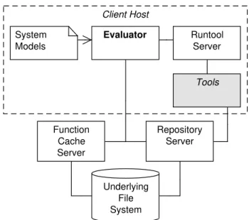
Diagram 2.1shows the parts of Vesta’s architecture that are relevant to us. One im-portant design decision in Vesta is that all sources are immutable, that is, every time a file is edited, a new version is created while the old one is kept.
Vesta, as well as Make, is not sensible to the semantics of the compilation units that it manipulates. Versions of sources and tools are immutable, what allowsRepeatable Builds: any version can be rebuilt at any time in future. Building is driven bySystem Models, which are descriptions that express how parts of the project are built and how to combine those parts into a final unit; it is a more sophisticated makefile counterpart. When a tool is spawned, a cache entry is created inFunction Cache Server, that maps the name of the tool, along with the arguments with which it was called, to the set of references that point to the artifacts that were generated. We should recall that everything is immutable in Vesta, therefore we can be sure that the files that are referenced don’t change, in any circumstance. Repository Server Underlying File System System Models Client Host Function Cache Server Tools Runtool Server Evaluator
Figure 2.1:Vesta’s architecture
ASystem Model describes how a certain application is built, and it is interpreted by theEvaluator, that communicates with other components in order to accomplish what is expressed in the system model. Tools are requested by the Evaluator to theRun Tool
2. RELATEDWORK 2.3. Eclipse Java Compiler
2.3
Eclipse Java Compiler
The Eclipse Java Compiler is an incremental compiler that compiles only what changed relatively to the previous compilation. The rational is that a modification of the source of the program should contribute proportionally to compilation time relatively to the ex-tension of such modification. Naturally, a compiler that follows this model has to cache results for each unit that it compiles. This technique exploits the fact that typically be-tween successive compilations there is a considerable amount of redundant work, unless the program was radically changed.
Eclipse JDT, a set of development tools shipped with eclipse, contains an incremental compiler, the Eclipse Compiler forJava (ECJ). ECJ compiler takes the idea further: it is able to run valid fragments of source code even when the whole file doesn’t compile, as long the invalid excerpt is not reachable from the fragment that is to be ran.
ECJis based on the incremental compiler ofVirtualAgeforJAVAan integrated devel-opment environment forJAVAdeveloped byIBM, but that was discontinued.
We are dealing with a compiler that has been designed and adapted to support incre-mental compilation, due to this being a promising path towards a faster compilation; it is, thus, of our interest to understand how other compilers achieve incremental compilation and, hopefully, adapt some of their ideas to our work.
2.4
Incremental Computation
So far, we’ve been analysing how some tools approach the problem of orchestrating com-plex build processes efficiently. The tools that we’ve studied were designed to a specific use case, however, it is notable that they share some characteristics: the use of depen-dency graphs to infer a minimal set of units to be compiled or built, and the caching of resources and their subsequent reuse. The computation model that we present follow, it is the more generalist of the models and therefore can be applied to far wider range of problems, although, we’ll also see that this model articulates exactly the aforementioned notions but in a more generic form.
2. RELATEDWORK 2.4. Incremental Computation
2.4.1 Self-Adjusting Computation
Self-Adjusting computation is an incremental computation model that was introduced by Umut Acar, as the theme of his dissertation for Phd, in 2005[Aca05]. Anadaptive program
minimizes what is recomputed in response to small changes of its input - relatively to the preceding execution. As an adaptive program executes, dependencies between data are captured into adependency graph, which is used, in further executions, to infer what needs to be recomputed. This is the most generalist model that we’ve discussed so far and can be applied to a wide range of problems.
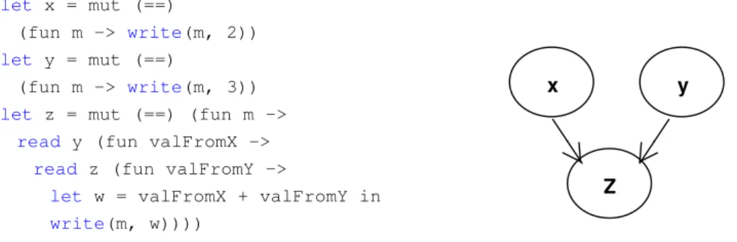
In this model, the smallest changeable unit is theMutable Reference. It can be either a memory cell or an expression that uses a value that is computed from another mutable reference. Mutable References and their dependencies form aDynamic Dependency Graph, which driveschanges propagation.Changes Propagationis the mechanism by which changes are propagated through the graph, triggering, along its path, re-evaluation of expressions that depend on changed data and subsequently marking them as changed too.
A functional program can easily be transformed into an adaptive program, by adapt-ing it to use a set of primitives: mod,read,write; and a set of meta-primitives: init,change
andpropagate[ABH01]. Any powerful enough underlying type system can enforce the correct use of those primitives [Car02]; for example, forcing the expression of a mod or a read to terminate with a write (soon we’ll understand why and how). Example2 exem-plifies an instantiation of this model as an Ocaml’s library.
Example 2.
module SelfAdjusting :
sig
type a’ mod
type a’ dest
type changeable
val mod: (’a * a’ -> bool) ->
(a’ dest -> changeable) -> a’ mod
val read: a’ mod * (a’ -> changeable) -> changeable val write: a’ dest * a’ -> changeable
val init: unit -> unit
val change: a’ mod * a’ -> unit val propagate: unit -> unit
end
2. RELATEDWORK 2.4. Incremental Computation
Modcreates amutable reference. Its first argument, whose signature is (’a * ’a -> bool), it is a comparison function that defines a conservative equality class between elements of generic type ’a; its role is testing if the reference’s value, after an explicit change, was effectively changed, in other words, if the new value is really different from the previous – this avoids triggering unnecessary changes propagation. Along with that function, it also receives an initializer function that initializes the mutable reference with a value.
Readreads a value from a mutable reference, its first argument, and applies it to an expression passed as second argument. This expression has return type "changeable", suggesting that it should terminate with awrite: unless the value of the mutable reference is ignored, an expression that reads that value becomes dependent upon the mutable reference that it refers.
Writewrites a value to a mutable reference and commits a dependency between the node that is read and the node that is written. Writes only appear in the context of read expressions or mod expression.
Dependencies: They arise from the use of reads, writes and mods. As the program is evaluated, a dynamic dependency graph is constructed, as those primitives are called. An edge is added whenever a write is committed in the context of a mod or read expres-sion. The edge’s source node is the mutable reference that is read, and its incidence is the mutable reference that is written. Edges are labeled withtime spans (t0, t1), where both
ti are time stamps;t0 is assigned before read’s expression is evaluated, andt after write
expression is committed. Anytotally ordered infinitesetTdefined on relation≤T is a valid
candidate to time stamp’s domain – It’s not specified a concrete structure. We say that edgee1is contained ine2ifT S(e1)is withinT S(e2).
let x = mut (==)
(fun m -> write(m, 2))
let y = mut (==)
(fun m -> write(m, 3))
let z = mut (==) (fun m ->
read y (fun valFromX ->
read z (fun valFromY ->
let w = valFromX + valFromY in
write(m, w))))
y
Z x
Figure 2.2:A functional self-adjusting program and the respective dynamic dependency graph
Example 3.
2. RELATEDWORK 2.4. Incremental Computation
emerge, consequence of the conditional expressions that may entail distinct call trees that depend on the input. When a certain mutable expression is recomputed, all edges that are within that expression’s time span become obsolete and subsequently are removed from the graph.
3
OutSystems Context
Our description of the platform is focused on the components that have a role in the publication process. As our ultimate goal is to improve the development experience, it becomes necessary to comprehend the developer’s workflow as well, hence we also briefly describe what developing with the OutSystems Platformconsists in. Finally, we provide an in-depth description of thepipeline, the process that compiles and deploys an application developed with the platform into a typical Web application.
An application is deployed to either one of two currently supported stacks: .NET or JAVA. Under the context of this work, the differences between the two are not significant, so we just focus on the .NET one. In the stack we used for this thesis, data is stored on MICROSOFTSQL SERVER DATABASE, server logic is leveraged by ASP.NET FRAME
-WORK(using the C# programming language), and the application is hosted by INTERNET
INFORMATIONSERVER(IIS).
3.1
The OutSystems Platform
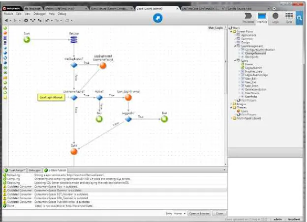
3. OUTSYSTEMSCONTEXT 3.1. The OutSystems Platform
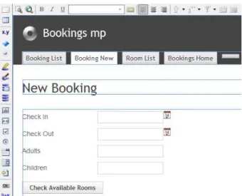
Figure 3.1:A typical development session on Service Studio
Despite the simplicity of developing with theOutSytems Platform, its language is ac-tually very rich and extensive. Due to its dimension, it would be too overwhelming to focus on the whole language, therefore we chose to prioritize a subset of its elements, under the criterion that the ones that are most frequently changed have more relevance to the compilation times.
3.1.1 The Language Elements
The OutSystems Platform provides a proprietaryVisual Domain Specific Languagethat al-lows the developer to work on all aspects of an application. The language aggregates a set concepts and metaphors that abstract the development of a application from the implementation details. To narrow the scope, we focus just a subset of those elements, justifying our choice with the developing metrics that are given in section 3.2. The el-ements are: Espace, Action, Entity, WebScreen, WebBlock, Stylesheet, Structure, Image, and
Javascript.
Espace
3. OUTSYSTEMSCONTEXT 3.1. The OutSystems Platform
Figure 3.2:The definition of an action
aConsumer, whereas the one that provides the element is aProducer. Modules are used to aggregate related functionality wrapped in a pluggable interface so other systems can reuse it, which makes them an fundamental building block for more complex systems.
Currently, the Espace is onlydeployment unit.
Action
Actionsare used to encode business logic, through the composition of visual elements, instead of the traditional programming languages that are text-based. Visually, an action resembles a graph, where the nodes are the action elements, and the control flow arrows are the edges.
AnActionmay be invoked from two different contexts: when some event on a screen is triggered: for instance, when a screen is loaded or when a button in aWebScreen is clicked on; or they may appear somewhere in the middle of some other action, as an action element itself.
Identified by a name, an Action defines an interface and an implementation. The interface specifies the action’s inputs and outputs. Inputs are values passed to the action at its invocation. Outputs are values that the action produces and that can be used by action elements on the context where the action was called. Values can be entity instances or basic types such as text, integers, dates, etc.
Developers define actions by connecting action elements using arrows that drive the control flow. An action element is the basic building block, that may be a control struc-ture, such as anif orforeach, action calls, queries to the database, among others.
3. OUTSYSTEMSCONTEXT 3.1. The OutSystems Platform
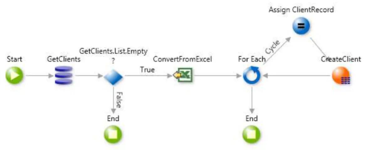
Figure 3.3:Entity’s attributes and actions Figure 3.4:Entity’s meta-information
database (a query element is represented by a stack of three purple cylinders). Then, it is followed by an IF element (whose icon is a losang) that checks if the list returned by the query is empty; if it is not, the action ends, otherwise, the execution continues: the Excel file is loaded. Each record in the file is iterated and inserted in the database. The orange element, labeled as "CreateClient", is an action call to one of the default actions that are automatically created for eachEntity.
Entity
An Entityabstracts and encapsulates access to a database’s table. It is described by a list of attributes, that correspond to database columns, and meta-data. For each defined entity, there is a set ofActions that perform basic CRUD (Create, Read, Update, Delete) operations over entity instances.
Web Screen
Web Screensare elements used to define dynamic web pages. Associated to aWeb Screen
there are variables, widgets and actions. The scope of screen local variables include the screen actions and the screen definition. Widgets are UI components that define an inter-face, which includes typical items like "input boxes", "buttons" or "links".
Web Block
AWeb Blockis a reusable web screen component that is used to build modular interfaces. Just like theWeb Screen, they are composed by Web Widgets, however, they are not web pages and they do not have an autonomous existence: they either exist inside a Web-Screenor otherWeb Block. AWeb Blockdepends on the parent component in which it is contained, which can be aWeb Screenor aWeb Block.
3. OUTSYSTEMSCONTEXT 3.1. The OutSystems Platform
Figure 3.5:Developer iterating a Web Screen in Service Studio
Figure 3.6:A Web Block that modularizes the user context panel
allow their manipulation.
Stylesheet
Cascading Style Sheets as defined byW3C. The following elements can have aCSS asso-ciated them:Web Screens,Web Blocks,Themes. ACSScan be global or local. A globalCSS
affects all UI elements of the application, while a localCSS affects particular elements, such as aWeb ScreenorWeb Block.
Structure
Structuresare containers that are used to store and manipulate data in memory, during an action execution, for example. AStructureinstance is similar to an entity instance in the sense that both are composed by a set of attributes, however, contrary to the entity counterpart, aStructureinstance is ephemeral as it only exists in memory.
Image
3. OUTSYSTEMSCONTEXT 3.2. Developer Workflow
Figure 3.7:A Structure
Javascript
AJavascriptis a Javascript snippet written by the developer. Typically, it is used when the developer wants to implement complex client logic that could not be implement uniquely through the facilities offered by the visual language.Javascriptsare encoded in the appli-cation model in raw.
Other Elements
We did not consider all theOutSystemsDSL since that would make the problem too ex-tensive for a dissertation context. Moreover, the elements that we chose cover most of the developers workflow, as proven at the section about theplatform usage patterns.
3.2
Developer Workflow
Understanding the user work-flow lets us to appreciate better the impact of publication times on the development experience. From previously collected metrics about the de-velopment patterns, we identify the model elements’ subset that are most often changed between publications. This metrics tells what we should prioritize in order to maximize the impact on perceived publication times and consequently on developer’s experience.
3.2.1 Change-Publish-Validate cycle
The Figure3.8illustrates the typical developer’s interactive workflow, where the devel-oper changes the application model using Service Studio, publishes using the develop-ment environdevelop-ment, and validates the results by testing the deployed application. This cyclic process goes on during development and maintenaince phases, which are basically the whole application’s lifetime.
3. OUTSYSTEMSCONTEXT 3.2. Developer Workflow
Figure 3.8:Developer’s Workflow
Figure 3.9:ServiceStudio notifying the user to errors in the model
3. OUTSYSTEMSCONTEXT 3.2. Developer Workflow
0% 10% 20% 30% 40% 50% 60% 70% 80%
Javascript Image Structure Entity Stylesheet Web Block Action WebScreen
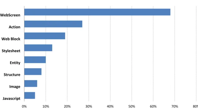
Figure 3.10:Top elements most changed between consecutive versions
3.2.2 Platform Usage Patterns
In order to improve the developer’s experience we need to know which are the actual usage patterns of the platform. We now show some metrics, previously collected by the
OutSystemsteam, for a typical set of projects, and obtained by analysing which are the most changed elements, and hence that are most often compiled.
These results account for 4715 publication operations and 15 different projects. From this data, we obtained the probabilities of each element being changed between succes-sive publications, and present it in figure3.10. The results reveal that the most frequently changed elements are in the UI components instances, such as Web Screen, Web Block,
3. OUTSYSTEMSCONTEXT 3.3. Platform Architecture
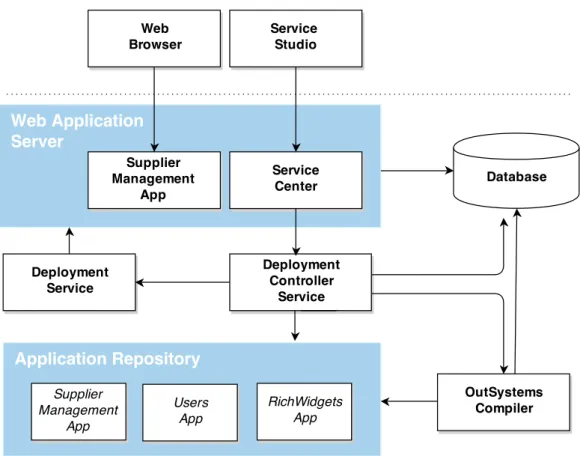
Figure 3.11:OutSystems Platform Server’s architecture
3.3
Platform Architecture
The OutSystems Platform has two major components: the Service Studio, the integrated development environment where the developer creates and develops applications, and thePlatform Server, where those applications are compiled and deployed. Both the com-pilation and deployment are aggregated in a single action called thePublication, which is performed on thePlatform Serverside.
InsidePlatform Server, there are smaller components, that assume different responsi-bilities in the publication, and cooperate to achieve an application’s publication. Figure
3. OUTSYSTEMSCONTEXT 3.3. Platform Architecture
Figure 3.12: An example of the structure of a deployed application.
3.3.1 Publication Overview
The publicationof a publication is a process that consists in transforming theApplication Modelinto a standard ASP.NET application and deploying it to the application server. Typically, the ASP.NET application has a structure akin to the one that is shown in figure
3.12. The result of publication comprises code in different languages and file formats. It includes:ASPXfiles andASCXfiles to define the web pages of the application,Stylesheets
and Javascript scripts to define the client’s behaviour, DLL assemblies that contain the application logic, and SQL scripts to define changes to the meta-model and migrate data and database schema.
These files are generated fromCompilation Units, which are the model elements that are transformed in files of some sort. Examples ofCompilation Unitsare the WebScreen
and theAction. Other important concept is theDeployment Unit. ADeployment Unitis a model element that can be compiled and deployed independently. Currently, only the Espace is aDeployment Unit.
An Espace is compiled into three assemblies:Main,CodeBehind, andProxy. Model elements that may be consumed by a Consumer Espace are compiled into theMain as-sembly (which are the majority), whereas CodeBehindreceives everything else that is private to anEspace(in this case, only the WebScreens). TheProxyassembly acts as layer between aConsumerand aProducer, by which the former consumes the elements exported by the latter. Further on, we will not care about theProxy’s role, because it is very specific and out of the context of this work.
Figure3.13shows the three phases that a publication goes through: Code Generation,
3. OUTSYSTEMSCONTEXT 3.3. Platform Architecture
Center. The Service Center drives the Deployment Controller Service throughout the pro-cess, dispatching the publication phases as the feedback it receives from theDeployment Controller Serviceis positive.
Figure 3.13:Publication’s phases
TheCode Generationphase begins; theDeployment Controller Servicedelegates the gen-eration of sources to the OutSystems Compiler. Associate to each model element that is aCompilation Unit, there is a set of transformation processes that generate the files. The
OutSystemscompiler handles the application model and recursively treats all model el-ements, executing all applicable transformations. The files generated in this phase are stored in the Applications Repository. The Application Repository is where applications’ code is compiled and stored to be deployed.
After the compiler finishes translating the model, the Deployment Controller Service
invokes the C# compiler to compile the source files into the set of assemblies mentioned above. The compiler groups the files among the assemblies they belong to. The first assembly that is compiled is theMain, followed by the compilation of theCodeBehind, which is then linked against theMain. These assemblies are also stored in theApplication Repository.
Generated files also include database scripts that update the database schema and data so that it conforms with the new data model. Scripts are executed at publication time, thus updating the data-model in the database as well as the application’s meta-data in the database.
TheDeployment Controller Serviceacknowledges theService Centerof the termination of the first two phases of the publication process, which then triggers the deployment through theDeployment Controller Service.
The Deployment Servicedeploys the application to theApplication Server. Recall that the application was stored in Application Repository, and that theDeployment Service re-quests the generated application to theDeployment Controller Service, which produces an archive containing all the deployable files. The last step of the publication process is taken by the Deployment Service, that makes the Application server (IIS) aware of a new application version.
3. OUTSYSTEMSCONTEXT 3.3. Platform Architecture
Figure 3.14:Publication’s Protocol
3.3.2 Compiler Pipeline per Model Element
The description of the compiler pipeline that we gave above does not consider the whole detail of the smaller processes performed over each particular kind of elements. In this section, we complete the description of the pipeline with the details of the compilation operations on individual model elements. All these descriptions should be understood in the context of the general compiler pipeline described at subsection 3.3.1.
AppendixAshows a comprehensive graphical explanation of the pipeline.
Espace pipeline
3. OUTSYSTEMSCONTEXT 3.3. Platform Architecture Application Server Shared Deploy Database Running App DLLs aspx files javascript files css files SQL scripts Application C# files / DLLs aspx files javascript files css files Application Model Actions Entities Screens Compile
Figure 3.15: Overall diagram of pipeline
Action pipeline
Actionsare directly transformed intoC#code. Acsfile is created for eachAction, which are compiled together into the MAINassembly, in the case of user-defined actions that can be used by otherESpaces, or into theCodeBehindassembly, in the case of Web Screen
actions.
WebScreen pipeline
During the Code Generation phase, two files are created: one aspx.csand one aspx, following the structure of a typical ASPX.NET application. The former contains visual structure of the screen, that is, markup with common ASPX metadata that, among other information, identifies the file as an ASPX page. The latter contains the serverC#code of theActionsbound to thatWebScreen.
InCompilation Phase, theaspx.cs, along with all the other files of the same type, are compiled into theCode Behindassembly. Theaspxis deployed, but theaspx.csis not, for it was already compiled into the assembly.
WebBlock pipeline
3. OUTSYSTEMSCONTEXT 3.4. Differential Code Generation DLL generation Deployment Phase CSC OutSystems Compiler Deployment Service Shared DLLs C# (Actions Structures) *.SQL Database Entity
Figure 3.16:Entity pipeline
Entity pipeline
During theCode Generation Phase, the OutSystems Compiler takes an entity definition in theApplication Model and generatesSQL scripts containing all the operations needed to update the database so it complies with the new metamodel. To create those scripts, the
OutSystems Compilerinspects the metamodel on the database and identifies the minimum sequence of SQL operations that have to be executed so the metamodel on the server becomes coherent with the new one. In addition,C#code is also created to implement the set of actions that are implicitly defined to manipulate instances of entities.
At theCompilation Phase, the C#source files are compiled into the Main assembly. Next, at theDeployment Phase,Deployment Controller Serviceexecutes theSQLscripts up-dating the database.
Structure pipeline
Structures are translated toC#source code that define their representation in memory, as well as operations that permit their manipulation in programmatic contexts, such as in a
Action. The produced source files are compiled into theMainassembly, because they can be exported by a producerEspace.
Stylesheets, Images, and Javascript
These elements are simply extracted from the application model and deployed along with all the other generated files.
3.4
Differential Code Generation
3. OUTSYSTEMSCONTEXT 3.5. Analysis of Publication Times
a differential publication was aborted by some reason. TheDifferential Compilationis an optimization introduced in the compiler previous to this work, and that targets only the
Code Generationphase. TheOutSystems Compilerruns in this mode for publications that occur after an integral publication. With this mode, only sources provided by the mod-ified model elements are regenerated. OutSystems internal benchmarks show that the Differential Compilation is 40% faster than the Integral counterpart.
The Differential is sustained above three principles:
1. Cache Invalidation
2. Merge
3. Cache Update
The OutSystems Compiler keeps a table in the filesystem that mapsModel Elements
to the files that they generated in previous publications, the Cache. Before a publication starts, aCache Invalidationhas to be triggered, because there are possibly parts of the cache that cannot be reused, for they no longer apply due to their elements had been changed or deleted. The Compiler identifies the model elements that did change by comparing their signatures. In addition, there are some rules that have to be executed in order to enforce constraints on model elements.
TheMergeadds to the reused model elements the new model elements. At the end of the publication, the cache is updated with the new model elements and the files that they generate.
3.5
Analysis of Publication Times
Now that we have a more complete notion of how applications are published, it is time to see how much takes to publish a typical medium size application, as well as how much time is spent on each phase. This will allow us to understand which are the phases less efficient and assay the effect of differential mode on the publication times.
Figure 3.17 shows those metrics for both the full publication and differential pub-lication of Lifetime, an OutSystems application that is used to manage the life cycle of deployed applications.
We are not interested in the Misc Steps times, as it regards steps that do not fall un-der the scope of this work. Figure3.17shows that the full publication takes roughly 38 seconds to compile, whereas differential publication takes 29 seconds. Despite slight os-cillations, the difference in times is very small for all the phases but theCode Generation
3. OUTSYSTEMSCONTEXT 3.6. Dependencies 0,0 2,0 4,0 6,0 8,0 10,0 12,0 14,0
Misc Steps CodeGeneration Compilation Deployment
t im e i n s Full Differential
Figure 3.17:Time spent on each phase
TheCompilationandDeploymentphases are the current bottlenecks of the publication, so they are now subject of our attention. To justify why the times for those two phases are high, we must recall that in the Compilation, two large assemblies are compiled for every publication, while in theDeploymentthe compiled application is fully deployed to theApplication Server. These are the key observations that will drive our proposal.
Note that from the observations presented above we conclude that the publication time is always bounded by the time it takes to compile those two assemblies plus the time it takes to deploy the complete application. This lower bound, which we denote by
L, is the minimum time a developer has to wait, independently of the number of elements he has changed after the last time he fired a publication. Ideally, the constant Lwould not exist; instead, publication times would depend primarily on the number of model elements changed by the developer.
3.6
Dependencies
There are many types of dependencies: two Web Screens bound by http link, a nested
Actioncall, aWeb Blockthat is contained inside other UI component, among others. Refer to example4for a common type of dependency.
3. OUTSYSTEMSCONTEXT 3.6. Dependencies
Matrix3.18shows all the dependencies that exist between the elements of the subset we are focusing on. These dependencies are the reason why theMainassembly is linked against theCodeBehind: the WebScreen, for instance, depends on Entity, but they be-long to different assemblies.
Recall thatService Studiovalidates the application model in real time as this is being changed. When an element’s interface changes, the Service Studio uses the dependencies graph to find all the elements that depend on it, so it can tell the developer about what become unsound.
WebScreen WebBlock Action Structure Entity Javascript Stylesheet Image
WebScreen ✓ ✓ ✓ ✓ ✓
WebBlock ✓ ✓ ✓ ✓ ✓
Action ✓ ✓ ✓
Entity ✓ ✓ ✓
Structure ✓
Javascript Stylesheet Image
4
Approach
TheCode Generation Phaseof theOutSystems compileris optimized to use an incremental strategy, by caching results for future reuse. All other phases of the compilation pro-cess are executed from scratch on each publication triggered by the developer. In the
Compilation Phase, the assemblies Proxy, Main, and Code Behind are compiled, and in theDeployment PhasetheDeployment Controllerdoes not distinguish between new and untouched components, which causes the deploying of the whole application. This is mainly due to granularity of the assemblies being generated, since any (partial) change will cause that at least one of these "big" assemblies to be modified. In chapter 2, we con-cluded that theCompilation Stepis the main bottleneck of the entire publication process, as it accounts for 39% of the total publication time.
The approach presented in this chapter should allow compile times to be somehow proportional to the expectations a developer has about the impact its changes have in the application model. For instance, changing the background color of a Web Screen should have a publication time close to zero. We propose to increase the granularity of compilation units, so that a change on a model element has a smaller impact on the compiled code, fits into a smaller assembly, which is faster to compile than the ones generated in the present model. Typically, the number elements changed by developers between publications is small. Hence, our approach is that of a increased compilation granularity, using thinner assemblies.
We present the notion ofAssembly Distribution, that defines a systematic distribution of model elements’ code by assemblies, and that can be parameterized to obtain different a compilation granularity. This mechanism is static in the previous model.
4. APPROACH 4.1. Refinement of the Deployment Units
Main Proxy
CodeBehind
Figure 4.1:Initial distribution and linking relationships
unit that produces data, and consumes data produced by other tasks, their predecessors or dependencies. Dependenciesenforce an execution (partial) order in which tasks ought to be executed.
The graph of tasks is defined by the dependencies, and calledTask Graph, is built at publication time and is executed by a user level parallelScheduler.
A task defines one operation, from a set of three available types: source code genera-tion,compilationof generated code units, anddeploymentof compiled code units.
4.1
Refinement of the Deployment Units
With finer modularization, a change on a model element has less impact on the recompi-lation of an application. Ideally, only the parts that changed or that depend on changed parts are compiled. This is the idea is exploited by tools such as Make or Incremental Compilers, that allow efficient build strategies which reuse as much as possible from bast builds. In the context of this work, we do not care about modules’ cohesion, that is, our approach to the modularization of the application has as aim the publication’s efficiency, and not so much if modules are “logical”, as the publication is transparent process and the developer is not aware of what applications are compiled into.
Until now, applications were compiled into just three assemblies:Main,CodeBehind, andProxy. BothCodeBehindandMainwere very dense, for the former contained the code from Web ScreensandWeb Services, while the later contained code for everything else. Figure4.1depicts those assemblies and the way they are linked with the previous model, from which we departed.
With this model, nothing could reused from past compilations, leading to redundant processing and inefficient executions. A single change would entail the compilation of the whole application. This inefficiency would ultimately entail publication that took longer than what the developer expected. By increasing the number of modules we aim for efficient aincremental publication mechanism.
4.1.1 Assembly Distribution
We begin by introducing a new notion. AAssembly Distributionis a publication’s param-eter that states how model elements are distributed by assemblies. More concretely, an
4. APPROACH 4.1. Refinement of the Deployment Units
functionΓthat maps model elements into assemblies inA. For convenience, we assume that model elements belong to a setM. For instance, the previous model is described by the distribution in which:
A={Main,CodeBehind}andΓ(o) = (
CodeBehind o∈WebScreensM
M ain otherwise
We do not considerate the Proxy in assembly distributions because as we said in subsection3.3.1this assembly assumes a special role that is to act as an interface between aProducer Espaceand itsConsumer. From now on, we just assume that all assemblies link against he proxy.
Moreover, a code level dependency betweenx and y is expressed bya → b, while linkage between assembliesa, b ∈ A is denoted bya ֒→ b. Recall that in table3.18are represented all the code dependencies for the elements that we are focusing.
Assembly Distributions are constrained by the code level dependencies between the model elements. Recall that model elements, prior to being compiled into assemblies, are transformed into source code, more specifically, they are transformed into classes that may depend on other classes generated from other elements. Figure4.2shows code level dependencies for the model elements that fall under the scope of this work. Refer to section3.6for a more in depth discussion about this matter. We do not considerJavascript
scripts norStylesheetsfor they have no dependencies.
For two assembliesaandb, ifahas an elementt1such thatt1 →t2, and ift2belongs
tob, thenamust link againstb. So, for two dependent elements, either they fall into the same assembly, or the assembly the dependent element is in has to be linked against the assembly where its dependency lives in. Moreover, elements should not be distributed in such way that there are cyclic dependencies between assemblies, otherwise compilation is not attainable.
ifa→bthenΓ(a) = Γ(b)orΓ(a)֒→Γ(b)
In chapter 4, we will present the iterative process that we undertook in order to find an adequate distribution, as well as the chosen one. The problem is stated as follows: Find anAssembly DistributionD, that is, a setAand a functionΓthat reduces the compilation times for differential compilations.
We anticipate already that one more factor has to be taken into account, the overhead of calling the framework’s compiler. While it is true that compiling smaller modules improves publication time, this strategy can lead to a inverse effect when number of the modules to compile is too large.
4. APPROACH 4.2. Task Oriented Model
WebBlock ESpace
WebScreen
Figure 4.2:Code Level Dependencies Hierarchy
compiled, but now there is a new toll, the increased number of calls to the C# compiler. Thereof, a more granular distribution entails a trade-off between decreaseddifferential compilationtimes and increasedfull compilation times. The challenge in finding a distribu-tion arises is in the balancing between the times for the two publicadistribu-tion modes. On one hand, if the times of a first publication are too high, the developer may create a negative first impression about the platform. On the other hand, aFull Publicationis triggered less frequently, so a even if its times increase, the impact is amortized throughout develop-ment.
Testing the distributions is thus necessary to avail more concretely their impact.
4.2
Task Oriented Model
Two assemblies can be compiled in any order as long as they do not depend on each other, which permits their parallelization. Parallel programming is hard, hence it demands abstractions that mitigate complexity and that are easier to us to reason about. Finding a suitable abstraction is the next goal. We observed that it is tractable to decompose the sequential publication model into a set of tasks with narrower responsibilities. We noted as well that the operations where the CPU would spent greater time intervals idle were:
1. Generation of source files;
2. Compilation of assemblies;
3. Introspection of the database.
4. APPROACH 4.2. Task Oriented Model
Figure 4.3:Task’s Class Diagram
form a graph: theTask Graph. Any execution model shall respect the semantics of depen-dencies between tasks, i.e, a task is not allowed to execute until after all of its dependen-cies have terminated.
During its lifetime, a task goes throughout five states:Instantiated (I),Ready (W), Run-ning (R),Finished (F), andError (E). A task always starts in theInstantiatedstate, and while it is in that state, it cannot execute. When all dependencies have terminated, the task is in theWaitingstate, that is, it’s allowed to run. It changes to theRunningstate when its execution is triggered (supposing it was allowed to do so). Once a task successfully ter-minates the job which was delegate to, it commutes to theFinishedstate. TheErrorstate is reserved for situations in which an anomaly occurred during the tasks’ execution.
F
I W R F
E
foralld : Dependencies
{ State(d) = Finished } Execute()
Failed Failed Failed
Finished Task
Figure 4.4:Task’s States
4. APPROACH 4.2. Task Oriented Model
Deployment tasks transport Deployment Units within remote nodes.
Figure 4.5:Task’s Class Diagram
4.2.1 Incremental Deployment Model
As anEspacegrows, more are the files theEspaceis compiled into, and therefore more is the I/O between between theCompiler Serviceand theDeployment Service, which is exac-erbated when theCompiler Serviceand theDeployment Serviceare distributed. Once again, we set out to apply the ideas about incrementally with which we tackle the problem of assemblies compilation.
Figure4.7 gives a glimpse of the protocol between theDeployment Controller Service
and the Deployment Service. Deployment Tasksdelegate the file transportation to the Dis-patcher, that then decides when it should dispatch the file to theDeployment Service. The
Dispatchershould also be responsible for batching requests when the load is heavier. The file cache is used to infer if a file should be updated or created on the front end, and that information accompanies the request made by theDispatcher, so theDeploy Serviceknows what to do with the file. The files to delete are found by examining the meta information that is used for the differential code generation.
4.2.2 Building the Task Graph
So far, we have talked about tasks but we have not yet made clear who and when they are created; ditto for they dependencies. Both may be created statically and dynamically.
Compilation Tasks are created dynamically as they depend on the Assembly Distribution Policythat is currently being enforced. For the rest, they are specified by the platform’s programmer, as we will now go to describe.
4. APPROACH 4.2. Task Oriented Model
Figure 4.6:Deployment Protocol
The Task Graph is the model that defines all the tasks that have to be executed for the impending publication, and implicitly defines the relative order in which they are executed through the their dependencies. TheTask Graph Orchestratoris who creates the taskTask Graph. It accomplishes that goal by using theApplication Model, to find which tasks need to be executed, and the Assembly Distribution Policy, to find which are the assemblies to be generated so that it creates a compilation task for each one of them.
TheTask Graphcreation is a process that comprises two steps. They are:
• Task Harvesting
• Dependencies Definition
InTask Harvesting, theorchestratorpicks from the model all theTask Providerthat are set to be compiled. For each one of those, it extracts their tasks and includes them into the set of taskGtasks. Then, theDistribution Policyis used to find the assembly where that element belongs. It is created the Compilation Task if it not exists and then it’s associated to it that element’s compilation tasks.
Before a publication is started, we have to infer which tasks to execute, we have to build a Task Graph. We defined a new annotation Task Provider. A Task Provider is an element which have tasks associated to: if a task provider is set as modified, the tasks it provides need to be executed for the imminent publication. We dubbed this step ofTask Harvesting: from the model, we look for all the modified Task Providers, and then we ask them for the tasks to execute. The tasks provided by the Task Provider might regard not only the provider itself, but also its descendants.
4. APPROACH 4.3. The Execution Model
Figure 4.7:Relationship between Task Graph Orchestrator and Assembly Distribution Policy
Figure 4.8:Assembly distribution
providers, instead they are created by aAssembly Distributor. The Distributor is param-eterized by an Assembly Distribution Policy, which defines which assemblies are created and map each compilation unit to the respective assembly. The distributor, driven by the Policy, distributes the Tasks providers for the Compilation Tasks, and each Compilation Task becomes dependent of the Compilation Tasks provided by the Provider.
Essentially, anAssemblyDistributionPolicyis astrategythat dictates in which assembly each type belongs to. This notion allows for more sophisticated strategies, that could use, for instance, statistical information about the developer’s patterns in order to generate optimal distribution strategies.
4.3
The Execution Model
4. APPROACH 4.3. The Execution Model
if our problem benefits from this strategy. Applications that rely heavily on I/O are im-proved in a parallel context, because I/O is slow and results in a suspension of the exe-cution, in which the application could be doing progress on other front of its execution.
The Execution model follows from aObserver-Notifierpattern and it comprises a sched-uler and set of workers (threads). This is depicted by diagram4.10. Each task assumes the role of a notifier, whereas the scheduler assumes the role of the Observer. This pat-tern allow us to keep orchestration logic separated from other aspects, such as logging, by having one observer that is a scheduler and other observer that is a logger. The Worker notifies each of its Observers of two events: when it starts executing a task (onTaskExecu-tion), and when it finishes the execution of the task(onTaskEndExecution).
Both the workers and the scheduler execute an event-loop, being asleep in the periods in which they have no work to do. Communication is achieved by asynchronous mes-sage passing – each worker waits on a queue with its mesmes-sages. Every time a workers begins or finishes working on a task, it notifies each one of its observers. The scheduler wakes whenever is notified of a task termination. On doing so, it updates the state of the ongoing execution, and then dispatches any task that might have become ready due to the termination of the task that triggered the event. The scheduler dispatches a task by assigning it to a free worker. When the Scheduler cannot dispatch a task because there is no free workers to whom delegate the task to, the task is kept in the waiting queue until a worker becomes free.
Figure 4.9:Scheduler’s Class Diagram
The process keeps living until all the tasks have been executed. If the task graph has no cycles and if no task ends up in an infinite loop, we have guarantees of progress and thus that the process eventually terminates. It is easy to prove this claim: if a task always finishes, every time a worker finishes its task, it can begin working on enqueued task. If the scheduler only assigns to workers tasks that have its dependencies satisfied, the workers will execute the tasks in topological order. Since task graph does not have cycles, we prove that the algorithm at some point terminates.