Setembro, 2014
Rita Valério Pontes
Licenciatura em Ciências de Engenharia de Materiais
Cellulose Nanorods in Liquid Crystalline
Elastomers for Improved Actuators
Dissertação para obtenção do Grau de Mestre em
Engenharia de Micro e Nanotecnologias
Orientador: Professora Doutora Maria Helena Godinho, Professora Auxiliar com
Agregação, Faculdade de Ciências e Tecnologia da Universidade Nova de Lisboa
Co-orientador: Doutora Susete Fernandes, Investigadora em Pós-Doutoramento,
CENIMAT/I3N
–
Departamento de Ciências dos Materiais, Faculdade de Ciências e
Tecnologia da Universidade Nova de Lisboa
Júri:
Cellulose Nanorods in Liquid Crystalline Elastomers for Improved Actuators
iii
‘
The beautiful thing about learning
Is that n
o one can take it away from you’
Cellulose Nanorods in Liquid Crystalline Elastomers for Improved Actuators
v
Cellulose Nanorods in Liquid Crystalline Elastomers for Improved Actuators
Copyright © Rita Valério Pontes, 2014.
Cellulose Nanorods in Liquid Crystalline Elastomers for Improved Actuators
vii
Ackownledgments/Agradecimentos
‘No man is an island, Entire of itself (…)’
John Donne
Antes de mais, agradeço à minha orientadora, Doutora Maria Helena Godinho todo o apoio dado no decorrer deste trabalho e por me ter confiado esta tarefa. Agradeço também à minha co-orientadora, Doutora Susete Fernandes, não só por toda a ajuda na parte experimental, mas também pelas correções na componente escrita. Acima de tudo, um grande obrigada por me ter ajudado a ultrapassar todos os obstáculos, pela sua paciência e compreensão. Ao Doutor Rodrigo Martins, pelos desafios, oportunidades e incentivos à investigação, ao longo destes cinco anos.
À Teresa, nada disto teria sido possível sem o teu apoio. Obrigada por nunca me deixares desistir e
por acreditares sempre em mim (e teres sempre pastilhas elásticas para todos…). Por me entenderes
melhor do que eu própria me entendo. Por toda a paciência que sempre tiveste para mim e por me mostrares que o mundo não é um lugar assim tão feio. Esta tese também é tua.
Ao Alex (migsy!!), agradeço a companhia de tantas horas nesta faculdade. Almoços, jantares, imperiais e caracóis, sábados, domingos e feriados. Por todos as Empreendo-cenas, aventuras nas Américas e mil projetos de loucura, por todos os ‘pitchos’ escritos, vitórias e danças de xugo nas
pseudo-derrotas. Quando formos milionários, vamos a um bar de charutos aleatório em Rayleigh, NC. Obrigada por tudo, Panda-Empreendedor. És uma pessoa incrível.
À Joana, por todos os momentos de loucura e longas conversas. Mostraste-me que eu também
“preciso de um siso” e que na verdade estamos todos destinados a fazer candeeiros e mojitos. Em Barcelona. “Ermehgerd, cerlelers!”
Ao Marreiros, agora careca, pelo companheirismo ao longo destes 5 anos. Estás mesmo a tornar-te um adulto...
À Rute, por me ensinar que o silêncio é, por vezes, uma virtude.
Anselmo (não o Ralph), obrigada por me mostrares que ser awkward é um dom. És o maior da aldeia e mereces toda a sorte do mundo.
Ao Trofas, obrigada por todos os nossos cafés tardios. Tenho muito para te agradecer e um par de linhas numa tese nunca será suficiente.
Zé Rui, és realmente “o” Mágico. A tua boa disposição e optimismo são contagiantes e sei que vais
chegar bem longe oh “farturas”!
À Susana das Frizes Groselha, unhas coloridas e mau feitio, obrigada pela paciência que sempre tiveste para me ouvir nas alturas mais complicadas. Agora prepara-te, que tens uma Odisseia pela frente.
À Meixeiro pelos náites e pelos chill-outs.
Ao Chico, que agora é “béta-testa”, e à Legolas quero agradecer pelas bifanas, pelos chás das cinco
e pelos after-hours no laboratório, sempre com boa-disposição.
Queria também deixar aqui uma dedicatória muito especial à máquina de café do edifício II, que raramente me desiludiu e muito me ajudou ao longo deste percurso.
Aúpe à Coro Echeverria, pelos ensaios de reologia e por me ensinar que a vida não é só feita de trabalho. Muchas gracias por todos os gins tónicos e pelos pitis partilhados, por todas as discussões e ensinamentos. Será sempre um prazer poder trabalhar contigo. “E bailar contigo. Una noche loooca
ooh-oooh-oh-ooooh”.
À Paula Soares, pelo FTIR, pelas palavras de incentivo e conselhos sábios. A idade torna-nos mesmo
Cellulose Nanorods in Liquid Crystalline Elastomers for Improved Actuators
viii
Ao Luís Aguirre agradeço acima de tudo a amizade e apoio que sempre me deu. E obrigada também por me ensinares que as empanadas ficam com bolhas quando são fritas. Prevejo grande utilidade para isto no meu futuro. Quando for pastar ovelhas na Colômbia. Ou Paraguai. Ou Argentina.
Ao Filipe Silvestre, expresso aqui toda a minha admiração pelo seu trabalho e agradeço a infinita paciência e ajuda em todo o processo de desenho e impressão 3D. Às vezes pareces ter super-poderes!
A todo o grupo de Soft and Biofunctional Materials do DCM, em particular ao Doutor João Canejo e ao Doutor Pedro Almeida, pela ajuda no desenvolvimento dos protótipos.
À minha “família” da PE (Delgado, Mé, Laurinha, Paciências, Carla, Marques, Ramalho, Sónia e Varzielas): obrigada por todos os jantares e longos serões. Acima de tudo, obrigada por me aturarem já há tanto tempo.
E como o mais importante vem no final, quero deixar aqui o meu mais profundo agradecimento aos meus pais. Por tolerarem as minhas ausências prolongadas e mau feitio. Por me terem apoiado em todas as etapas deste percurso. Por sempre terem acreditado em mim e terem feito de mim a pessoa que sou hoje.
ix
Abstract
Nanotechnology plays a central role in ‘tailoring’ materials’ properties and thus improving its
performances for a wide range of applications. Coupling nature nano-objects with nanotechnology results in materials with enhanced functionalities.
The main objective of this master thesis was the synthesis of nanocrystalline cellulose (NCCs) and its further incorporation in a cellulosic matrix, in order to produce a stimuli-responsive material to moisture. The induced behaviour (bending/unbending) of the samples was deeply investigated, in order to determine relationships between structure/properties.
Using microcrystalline cellulose as a starting material, acid hydrolysis was performed and the NCC was obtained. Anisotropic aqueous solutions of HPC and NCC were prepared and films with
thicknesses ranging from 22μm to 61μm were achieved, by using a shear casting technique.
Microscopic and spectroscopic techniques as well as mechanical and rheological essays were used to characterize the transparent and flexible films produced. Upon the application of a stimulus (moisture), the bending/unbending response times were measured.
The use of NCC allowed obtaining films with response times in the order of 6 seconds for the bending and 5 seconds for the unbending, improving the results previously reported. These promising results open new horizons for building up improved soft steam engines.
Cellulose Nanorods in Liquid Crystalline Elastomers for Improved Actuators
xi
Resumo
A nanotecnologia representa um papel central na manipulação das propriedades dos materiais e nas suas melhorias ao nível do desempenho, para um vasto conjunto de aplicações. Conjugar nano-objetos da Natureza com a nanotecnologia permite-nos obter materiais com funcionalidades melhoradas.
O principal objetivo desta tese era a síntese de celulose nanocristalina (NCC) e a sua incorporação numa matriz celulósica, de forma a produzir um material capaz de responder a um estímulo - humidade. O comportamento induzido nas amostras (bending/unbending) foi investigado a fundo, para determinar as relações entre estrutura e propriedades
Partindo de celulose microcristalina, foi possível obter NCC por hidrólise ácida. Prepararam-se soluções anisotrópicas de hidroxipropilcelulose (HPC) e NCC e, recorrendo à técnica de espalhamento shear casting, foram produzidos filmes com espessuras entre 22μm e 61μm.
Para caracterizar os filmes flexíveis e transparentes obtidos, foram utilizadas técnicas microscópicas e espetroscópicas, bem como ensaios mecânicos e reológicos. Sob a aplicação de humidade, os tempos de resposta (bending/unbending) das amostras foram medidos.
A utilização de NCC permitiu obter filmes com tempos de resposta na ordem dos 6 segundos para o bending e 5 segundos para o unbending, evidenciando melhorias relativamente aos resultados anteriormente publicados.
Estes resultados promissores abrem um novo horizonte no que diz respeito à criação de mecanismos melhorados (soft steam engines).
Cellulose Nanorods in Liquid Crystalline Elastomers for Improved Actuators
xiii
Table of Contents
1. Introduction ... 3
1.1. Brief introduction to Liquid Crystals ... 3
1.2. Liquid Crystalline Elastomers ... 5
1.3. Cellulose and Cellulose derivatives as functional materials ... 5
1.3.1.
Hydroxypropyl cellulose (HPC) ... 6
1.4. Nanomaterials ... 6
1.4.1.
Nanocrystalline Cellulose (NCC) ... 6
1.4.2.
Tailoring properties at the nanoscale ... 7
1.5. Soft Motors ... 7
2. Materials and Methods ... 9
2.1. Production of HPC and HPC/NCC films ... 9
2.2. Shear Casting Knife adaptation: reduce the minimum speed ...10
2.3. Production of a soft motor ...10
2.3.1.
3D Printing ...11
2.4. Characterization ...12
3. Results and Discussion ...15
3.1. HPC Matrix ...15
3.1.1.
HPC from two different suppliers ...16
3.1.2.
Alfa Aesar HPC as Matrix ...20
3.2. NCC Filler ...21
3.3. HPC/NCC nanocomposite ...24
4. Conclusion and Future Perspectives ...33
5. References ...35
6. Supporting Information ...39
6.1. 3D Modelling ...39
6.2. Detailed Thickness Study ...39
6.3. Statistical Distribution of Aspect Ratios ...41
6.4. Production of a mould ...44
Cellulose Nanorods in Liquid Crystalline Elastomers for Improved Actuators
xv
List of figures
Figure 1.1- (a) Schematic of molecular order of crystalline, liquid crystalline and isotropic phases (b) Different molecular shapes, that can originate liquid crystalline phases ... 3
Figure 1.2- Schematic representation of a: (a) Nematic phase; (b) Cholesteric structure, where P/2 is half of the cholesteric pitch ... 4
Figure 1.3 - Chemical structure of Hydroxypropyl cellulose, where R=H or R=CH2CH(OH)CH3. The
maximum value of the degree of substitution (DS) of HPC is 3, while there is no theoretical maximum limit of molecular substitution (MS). ... 6
Figure 1.4 – Schematics of molecular ordering in crystalline and amorphous regions, inside cellulose microfibrils... 7
Figure 2.1 - Schematic representation of the different paths involved in the NCC synthesis and film preparation. Starting from (a) microcrystalline cellulose, an acid hydrolysis is performed, resulting in a (b) suspension of NCCs in water. By adding HPC, an (c) anisotropic solution is obtained and (d) shear-casted in the shape of a film. ... 9
Figure 2.2- Schematic representation of the shear-casting apparatus used to produce films of lyotropic liquid crystalline solutions of HPC and HPC/NCC with different thickness. The thickness of the films can be controlled by the gap and velocity of the Gardner Knife... 10
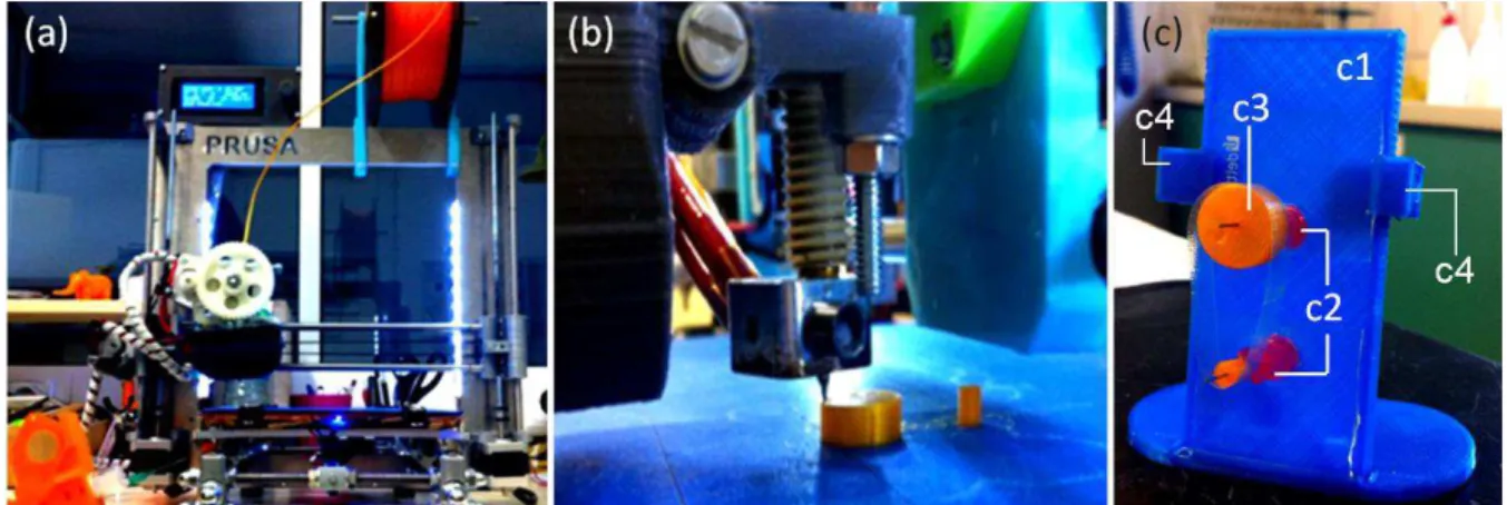
Figure 2.3 – (a) Schematic of the soft motor, showing the location of the cellulosic film, moist air and rotation direction. The alignment direction is parallel to the axes of the wheels. The free surface of the film is on the outer side of the device. Initially (b1), the lever arms (in green) have equal length. The application of a stimulus (b2) leads to a deformation of a cellulosic film, shortening one of the lever arms. The torque (T), which was initially zero, will now promote a counter clockwise rotation. [8] ... 11
Figure 2.4 - (a) PRUSA 3D Printer, (b) printing process of the wheels, (c) final stand with all the components assembled. In blue (c1), the main structure of the stand with the mounted axis (c2), the printed wheels (c3) and the lateral clamps (c4)... 12
Figure 3.1 – POM images of films of HPC from the supplier (a) Sigma Aldrich and (b) Alfa Aesar prepared from aqueous solutions of 60% (w/w) with parallel polarizers and the corresponding photographs of (c) Sigma Aldrich and (d) Alfa Aesar HPC films. The shear direction is indicated with an arrow. || indicates the polarizers are parallel to each other ... 16
Figure 3.2 - Transmission polarizing optical microscopy images, taken between crossed polarizers of films of HPC from the suppliers (a) Sigma Aldrich and (b) Alfa Aesar, prepared from aqueous solutions of 60% (w/w) and shear-casted with a Gardner knife. ... 17
Figure 3.3 - Scheme of a HPC film’s free surface (contact with air) bending when exposed to moisture.
... 18
Figure 3.4 – Series of video frames showing the bending of the top surface of free standing films of HPC from the two suppliers (a) Alfa Aesar and (b) Sigma Aldrich, with thicknesses approximately 22
μm and 29 μm, respectively, when exposed to moisture. The shear direction is marked with a blue arrow on the films’ surface... 19
Figure 3.5 - XRD diffractogram for a film of Alfa Aesar’s HPC prepared from an aqueous solution of
Cellulose Nanorods in Liquid Crystalline Elastomers for Improved Actuators
xvi
Figure 3.6 - SEM pictures of the cross section of the sheared HPC films. A layered structure parallel to the films surface can be observed with periodic spacing in the range of microns. ... 20
Figure 3.7 – X-Ray diffractograms of the pure MCC source (Avicel) and a thin film obtained from the synthesised NCCs. ... 22
Figure 3.8 - Infrared spectrum of a thin film (42 μm) obtained from evaporation of a NCC aqueous
suspension (0.6% w/w) ... 23
Figure 3.9- SEM micrograph of a dispersion of isolated cellulose nanocrystals, obtained via chemical hydrolysis ... 23
Figure 3.10- Top view images of the surface’s amplitude scan of a NCCs’ film casted from an aqueous
suspension of NCC (0.5% w/w) ... 24
Figure 3.11 - (a) Infrared spectra of HPC films with different concentrations of NCC, (b) detailed spectra of the same films, where the appearance of a peak at 2918 cm-1 wavenumber is observable.
The content of solids in the composite is approximately 60% (w/w). ... 24
Figure 3.12 – XRD diffractograms obtained for two samples of HPC films with different concentrations of nanocrystalline cellulose incorporated. The content of cellulose in the composite is approximately 60% (w/w). ... 25
Figure 3.13 – 3D topography image (20 × 20 μm2 scan) of the free surface of a sheared HPC film with 1.0% (w/w) of NCC incorporated. The film was prepared from an aqueous anisotropic solution with 60% (w/w) of cellulose and casted at a shear rate of 1.25 mm s-1. ... 26
Figure 3.14 - Transmission polarizing optical microscopy images, taken between crossed polarizers of HPC films with (a) 0.4% and (b) 0.83% of NCCs, obtained by shear casting of anisotropic solutions. The shear direction is indicated with an arrow. ... 26
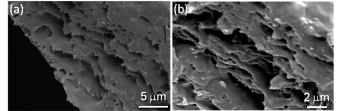
Figure 3.15 –SEM micrographs of a cross-section (perpendicular to the shear casting direction) sample of HPC with 0.05% (w/w) of nanocrystalline cellulose ... 27
Figure 3.16 - FIB-SEM micrographs of (a) a cross-section (parallel to the shear casting direction) sample of HPC with 2.0% (w/w) of nanocrystalline cellulose and (b) the detail of a fissure between layers. ... 27
Figure 3.17- FIB-SEM micrographs of a cross-section (perpendicular to the shear casting direction) sample of a film of HPC with 2.0% (w/w) of nanocrystalline cellulose ... 28
Figure 3.18 - Flow curve experiments for (■) HPC and solutions of HPC with (●) 0.1%, (▲) 1.0% and (▼) 2% of NCCs, obtained at a range of shear rates between 0.001 to 1000 s-1. ... 28
Figure 3.19 – (a) Bending and (b) unbending movement of the top surface of a sample (with dimensions 1.5cm × 1.5cm × 30μm) obtained by shear casting of an anisotropic solution of HPC with 0.5% of NCCs. The overall content of cellulose on the aqueous solution was approximately 60%
(w/w).The shear direction is marked with an arrow on the films’ surface. ... 30
Figure 3.20 - (a) Bending and (b) unbending movement of the top surface of a sample (with dimensions 1.5cm × 1.5cm × 45μm) obtained by shear casting of an anisotropic solution of HPC with 1.0% of NCCs. The overall content of cellulose on the aqueous solution was approximately 60%
xvii
Figure 3.21 - (a) Bending and (b) unbending movement of the top surface of a sample (with dimensions 1.5cm × 1.5cm × 61μm) obtained by shear casting of an anisotropic solution of HPC with 1.0% of NCCs. The overall content of cellulose on the aqueous solution was approximately 60% (w/w).The shear direction is marked with an arrow on the films’ surface. ... 32
Figure 6.1 –Three dimensional drawings of (a) the wheels and (b),(c) the motor’s stand ... 39
Figure 6.2 – Series of vídeos frames showing (a) bending and (b) unbending movement of the top surface of a sample (with dimensions 1.5cm × 1.5cm × 11.3μm) obtained by shear casting of an
anisotropic solution of HPC 60% (w/w).The shear direction is marked with an arrow on the films’
surface. ... 40
Figure 6.3 – Series of vídeos frames showing (a) bending and (b) unbending movement of the top surface of a sample (with dimensions 1.5cm × 1.5cm × 21.1μm) obtained by shear casting of an
anisotropic solution of HPC 60% (w/w).The shear direction is marked with an arrow on the films’
surface. ... 40
Figure 6.4 – Series of vídeos frames showing (a) bending and (b) unbending movement of the top surface of a sample (with dimensions 1.5cm × 1.5cm × 22.2μm) obtained by shear casting of an
anisotropic solution of HPC 60% (w/w).The shear direction is marked with an arrow on the films’
surface. ... 40
Figure 6.5 - SEM micrograph of a dispersion of isolated cellulose nanocrystals, obtained via chemical hydrolysis ... 41
Figure 6.6 - SEM micrograph of a dispersion of isolated cellulose nanocrystals, obtained via chemical hydrolysis. ... 42
Figure 6.7 – Normalized Gaussian curve, centered in the average aspect ratio calculated ... 42
Figure 6.8 – Photographs of the mould produced, with the two components, including an inner cylinder with diameter 2 cm. ... 44
Cellulose Nanorods in Liquid Crystalline Elastomers for Improved Actuators
xix
List of tables
Table 3.1–Young’s modulus (E), tensile stress (UTS) and strain deformation (ε) of the films prepared
from an HPC 60% (w/w) water liquid-crystalline solution. Par and Per means that the mechanical stress-strain measurements were performed along the parallel and the transverse directions to the
shear casting direction, respectively ... 18
Table 3.2 – Response times for the bending and unbending of free standing HPC films’ top surface with different thicknesses ... 21
Table 3.3 - Crystallite size and crystallinity index of the NCC film and comparison with the MCC source ... 22
Table 3.4 – Interplanar spacing for HPC samples with different concentrations of nanocellulose ... 25
Table 3.5 – Measurements of the periodicities in the surface of a sheared HPC film with 1.0% (w/w) of NCC incorporated, where ∆l1 and ∆l2 represent the spacing between large and small bands, respectively. ... 26
Table 3.6 – Spacing between gratings in HPC films with different contents of nanocrystalline cellulose. The content of cellulose in the composite is approximately 60% (w/w). ... 27
Table 3.7 - Young’s modulus (E), tensile stress (UTS) and strain deformation (ε) of the films prepared from aqueous Anisotropic solution of HPC with different concentrations of NCCs. Par and Per means that the mechanical stress-strain measurements ... 29
Table 3.8 – Thickness for HPC films with identical method of preparation but different content of nanocrystalline cellulose. The content of solids in the precursor solutions was 60% (w/w) in all the samples ... 30
Table 6.1 – Experimental conditions and thicknesses obtained ... 39
Table 6.2 – Average dimensional measurements and standard deviations ... 42
ii
Symbology
R
Attached Hydrogen or a hydrocarbon side chain of any length𝐷𝑆
̅̅̅̅
Average Degree of Substitution𝑀𝑆
̅̅̅̅
Average Molecular Substitutionn
Director (unitary vector)ℎ
Distance between knife and substrateP
Cholesteric Pitchw/w
Mass FractionM
̅
n Number Average Molecular WeightS
Order Parameter𝛾̇
Shear rateɛ
Strain Deformationσ
StressT
Temperaturet
TimeT
N-I Transition Temperature Nematic-isotropic𝑣
Velocityη
ViscosityE
Young’s ModulusCellulose Nanorods in Liquid Crystalline Elastomers for Improved Actuators
iv
Abbreviations
AFM Atomic Force Microscopy
AGU Anydroglucose Unit
C* Cholesteric
CCW Counter Clockwise Direction
CW Clockwise Direction
DS Degree of Substitution
FIB Focused Ion Beam
HPC Hydroxypropyl Cellulose
LC Liquid Crystal or Liquid Crystalline
LCE Liquid Crystal Elastomer
MS Molecular Substitution
N Nematic Phase
NCC Nanocrystalline Cellulose
Par. Parallel to shear (direction)
Per. Perpendicular to shear (direction)
PLA Poly(lactic acid)
POM Polarized Optical Microscopy
RPM Revolutions per minute
SEM Scanning Electron Microscopy
UTS Ultimate Tensile Strength
Cellulose Nanorods in Liquid Crystalline Elastomers for Improved Actuators
1
Objectives
The main objective of this work was to prepare and characterize the mechanical response of films prepared from liquid crystalline (LC) cellulosic systems, in order to build up cellulose-based stimuli -responsive devices. LC cellulosic materials can be shaped differently and therefore have potential applications in not only in macro but also micro and nanoengineering.
Anisotropic films were prepared by using a shear casting technique and were found to be moisture-sensitive. By playing with the orientational order, which is coupled with the mechanical strain, bending and unbending movements were induced in the films.
Taking profit of these motions, a soft motor device was idealized. In order to pursuit this objective, a prototype was designed and 3D-printed.
Cellulose Nanorods in Liquid Crystalline Elastomers for Improved Actuators
3
1. Introduction
1.1. Brief introduction to Liquid Crystals
“Crystals that flow”.
This was the exact expression Otto Lehmann used in 1904 to describe liquid crystals (LCs), in his book Flüssige Kristalle, which was the first book dedicated to this state of matter. Despite the date of publication, Lehmann’s studies in this field started around 1889, having introduced the use of the
polarizing optical microscope (POM) coupled with a heating stage to study LCs, as well as identifying birefringence (crystals) and flow (liquids) in this type of materials.
Over several years, many physicists and chemists tried to understand this state of matter, as well as its properties. Nowadays, Liquid Crystals are used in several applications such as electro-optical devices and flat panel displays. These materials stand out for having remarkable properties, such as intermediate behaviour between crystalline solids and flowing liquids. It is long known that in the crystalline phase molecules present well defined spatial positions. In this type of materials, there is a long range periodic order in three dimensions. On the other hand, on the isotropic phase (liquids), there is no long-range orientational order. [1] So, as a mesophase (meso-intermediate from latin), liquid crystals exhibit a state of order between the crystalline and the isotropic, as shown on Figure 1.(a)
Regarding the formation of the mesophase, liquid crystals may be classified as thermotropic or lyotropic. In thermotropic LCs, the transition between phases (solid – LC – liquid) is induced by temperature, while in lyotropic LCs, the formation of the mesophase is induced by a variation of the concentration (dissolution/solvation).[2]
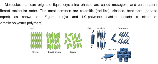
Molecules that can originate liquid crystalline phases are called mesogens and can present different molecular order. The most common are calamitic (rod-like), discotic, bent core (banana shaped) as shown on Figure 1.1(b) and LC-polymers (which include a class of aromatic polyester polymers).
Figure 1.1- (a) Schematic of molecular order of crystalline, liquid crystalline and isotropic phases (b) Different
molecular shapes, that can originate liquid crystalline phases
Cellulose Nanorods in Liquid Crystalline Elastomers for Improved Actuators
4
Another important feature of liquid crystals is the remarkable optical properties. While in isotropic media (like fluids) there is only one refraction index, in anisotropic media (like LC), different refraction indexes depending on the direction of the light propagation, can be observed. This phenomenon is designated as birefringence and is the reason why liquid crystals are being used, nowadays, in optical fibers [3] and other photonic devices. [4]
.It is possible define the director n as a two-headed vector that provides the average direction of the alignment of molecules. Thus, one may also define θ as the angle between a single molecule and
the director n.
The molecules do not necessarily all point in the same direction, however there is a preferred molecular orientation, at a given point r, described by a unit vector n(r), which may suffer thermal fluctuations. A thermodynamic parameter can be defined to characterize the order of the nematic and is given by:
〈S〉 = 〈32 cos2θ −1
2〉 (1.1)
where the brackets denote an average over many molecules at the same time or the average over time for a single molecule. [5] In an ordered state, all the molecules are oriented and θ=0° which, trivially, leads to S=1. Alternatively, in a disordered state (as an isotropic fluid) the molecular axis point in all directions with equal probability, which leads to S=0.
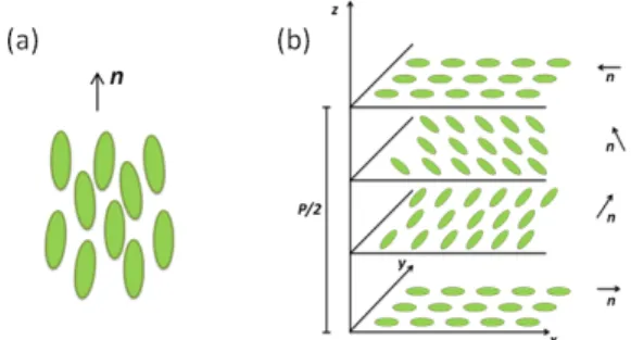
The nematic phase is the simplest case of a mesophase, where the molecules exhibit long range ordering but no positional ordering. Recalling the concept of director n, the rod-like molecules in this mesophase tend to align with their long axis somehow parallel to the director, as shown on Figure 1.2 (a).[6]
Figure 1.2- Schematic representation of a: (a) Nematic phase; (b) Cholesteric structure, where P/2
is half of the cholesteric pitch
For a nematic phase to occur, each molecule must be achiral (each molecule must be identical to its mirror reflection) or, otherwise, it is only possible to have a nematic phase when the system is a racemic mixture (1:1) of left-handed and right-handed species.[7]
5
the optical axis and following a helical trajectory, as represented on Figure 1.2(b). The pitch (P) is defined as the spacing between layers until the director performs a rotation of 360°.
The P values are usually in the order of magnitude of the optical wavelength, leading to an interaction between the light and the structure. This spacing may be modified by changing the temperature and concentration. Thus, it is possible to engineer the gap in order to observe different colours by changing the Bragg scattering of light. However, by changing temperature some cholesteric phases present a critical temperature (T*) at which the pitch tends to infinite and the chiral nematic phase behaves as a conventional nematic. Despite the similarities/intimate relation with nematic phases, chiral nematics only occur in non-racemic systems (i.e., molecules different from their mirror image).[7]
1.2. Liquid Crystalline Elastomers
Based on liquid crystals and adding properties of polymers and rubber elasticity, a new category of materials was created: Liquid Crystal Elastomers. This exclusive class of functional materials exhibits a remarkable behaviour not seen in either elastomers or LCs separately. Nowadays, this type of materials is used as actuators, cantilevers or micro-motors.
Elastomers are rubber-like solids characterized by an elastic modulus of the order of MPa which can accommodate strains of over 100%. We may define Liquid Crystal Elastomers (LCEs) as cross-linked polymer networks with orientationally ordered mesogenic units, with the unique ability to couple mechanical strain and orientational order. As a consequence, any change in orientational order will result in mechanical strain, causing a change in the sample’s shape. Changes in the order parameter may be caused by heating, illumination, exposure to electric fields or the presence of chemical solvents, giving rise to corresponding changes in sample shape. [8] Also, the incorporation of nanoparticles into LCEs has been of considerable recent interest, with the aim of achieving a faster response speed and better control over the actuation.[9]
1.3. Cellulose and Cellulose derivatives as functional materials
Cellulose is the polymer selected by Nature to build up the plant’s world, is an abundant and renewable resource found in most parts of the world, which makes it a cheap raw material for various applications [10]. Cellulose belongs to a family that can form cholesteric liquid crystalline (LC) phases, exhibiting remarkable optical properties as a result of their photonic band structure, and applications such as polarized light sources, information displays and storage devices
Cellulose Nanorods in Liquid Crystalline Elastomers for Improved Actuators
6
1.3.1. Hydroxypropyl cellulose (HPC)Hydroxypropyl cellulose (HPC) is a cellulosic derivative obtained by hydroxypropylation of the hydroxyl groups in the repeating unit of cellulose, as shown in Figure 1.3. As other cellulose derivatives, HPC also takes part in a large and established industry and is used in pharmaceuticals, food, personal care, construction, oil field chemicals, textiles, adhesives, ink paper, coating, among several others.
This compound was reported to form both thermotropic and lyotropic mesophases, in suitable solvents. In aqueous solution, HPC is known to form a lyotropic phase. The critical concentration, at room temperature, varies with polymer characteristics. However, HPC is usually able to form a LC phase at concentrations between 41% (w/w) and 80% (w/w).[11] The use of this cellulose derivative in stimuli-responsive systems has been already described in literature [8][12][13][14].
Figure 1.3 - Chemical structure of Hydroxypropyl cellulose, where R=H or R=CH2CH(OH)CH3. The maximum
value of the degree of substitution (DS) of HPC is 3, while there is no theoretical maximum limit of molecular substitution (MS).
1.4. Nanomaterials
One of the main interests of nanotechnology is the possibility to alter material’s properties,
making them totally customizable. This opens a whole new world of possibilities and over the last decades, there has been a crescent interest in creating materials with improved performance, to potentiate new applications and optimize existing ones. This type of approach implies the manipulation of atomic bonds – at the nanoscale – assigning nanotechnology with the central role in this process.
1.4.1. Nanocrystalline Cellulose (NCC)
Lately, nanocrystalline cellulose (NCC) has drawn a lot of attention due to the properties of the materials it can originate (light weight, stiffness, transparency)[15][16][17], being used in a wide range of areas, from pharmaceuticals [18] to electronics [19].At the nanoscale, interfaces represent an essential role and due to the high surface area, nanomaterials are being used as fillers in composites, assuring perfect interfaces with the matrices. This way, it is possible to distribute mechanical solicitations through all the material. [20]
When using a filler with a chemical structure similar to the matrix, this interface is expected to be almost perfect. In this way, nanocrystalline cellulose states itself as an obvious filler for composites
based on cellulose derivatives, creating the ‘all-cellulose composites’.[21]
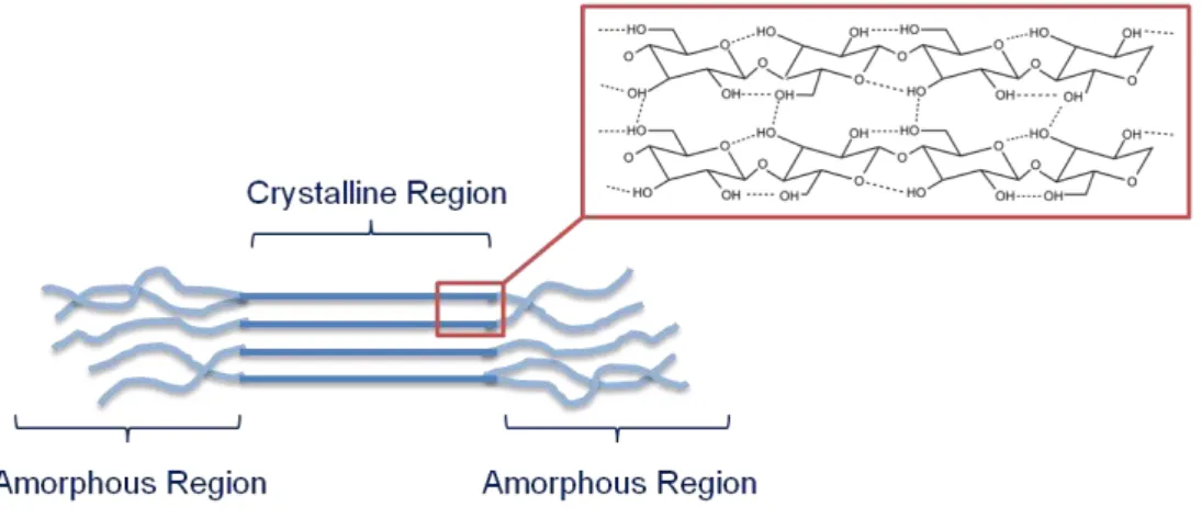
NCCs may be easily obtained via chemical reaction, by separating crystalline and amorphous
7
Figure 1.4 – Schematics of molecular ordering in crystalline and amorphous regions, inside cellulose
microfibrils.
1.4.2. Tailoring properties at the nanoscale
Cellulose nanocrystals may be incorporated in other polymeric matrices, in order to enhance mechanical properties. In the present case, by using a cellulosic matrix (HPC) we are able to achieve an all-cellulose composite. Both materials have a similar chemical structure, which provides better interaction between the two materials. Therefore, the composite is expected to present improved
mechanical properties regarding Young’s modulus and tensile strength.[13]
By using a solvent-vapour as a stimulus, it was found that anisotropic HPC matrices can change shape, by playing with the order parameter [8]. One can expect that despite of the NCC not being
“activated” by the stimulus, the material still responds, depending on the NCC’s concentration. When the stimulus is removed, the HPC domains will relax to the original state, being driven by the
nanorods’ orientation, which is translated to a much faster relaxation time. Besides the possible advantages referred, we must keep in mind that by adding a filler to the nanocomposite, we anticipate a trade-off between mechanical properties and the performance as an actuator.
1.5. Soft Motors
In 2008, Yamada et al. [22] demonstrated, for the first time, a light-driven plastic motor. This device was able to directly convert light energy into mechanical work (photomechanical effect), taking
advantage of the cooperative movement of mesogen’s and polymer segments in a liquid-crystalline elastomer containing azobenzene derivatives. The cromophores incorporated in the structure of this LCE suffer a trans-cis photoisomerization when irradiated with UV light, leading to a photoinduced phase transition. The changes in the alignment of mesogen’s at the microscopic scale are thus
reflected in significant macroscopic changes in order.
Cellulose Nanorods in Liquid Crystalline Elastomers for Improved Actuators
9
2. Materials and Methods
2.1. Production of HPC and HPC/NCC films
HPC was purchased from Sigma–Aldrich (𝑀̅𝑤=100.000; 𝑀𝑆̅̅̅̅=3.5; 𝜂 5%,25°𝐶= 125𝑐𝑝𝑠) and Alfa Aesar (𝑀̅𝑤=100.000; 𝑀𝑆̅̅̅̅=3.5; 𝜂 5%,25°𝐶= 89𝑐𝑝𝑠) and used as received. Avicel (microcrystalline
cellulose ~ 50μm particle size) was acquired from Sigma-Aldrich.
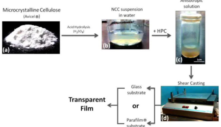
Nanocrystalline cellulose particles were prepared on the basis of the methods of Gray et al. [23][24] and Orts et al. [25] with minor adaptations. Microcrystalline cellulose was hydrolyzed with sulfuric acid (97%, p.a., Merck) with an acid/solid ratio of 16:1 at 45°C for 130 minutes under vigorous stirring. The resultant suspension was washed with ultrapure water by successive dilution and centrifugation (at 12000 rpm for 20 minutes) until the supernatant was turbid (which occurs at approximately pH 1.9–3.8). The resulting suspension was placed in a Spectra/Por 4 cellulose membrane (Spectrum) and dialyzed against ultrapure water until a pH of 6–7 was reached. A suspension of NCC in water was obtained. The content of NCC in the suspension was, when need, increased by subsequent centrifugations (at 14000 rpm for 20 minutes) and a gel-type substance was obtained. The water used in these experiments was purified by using a Millipore Elix Advantage 3 purification system. The synthesis of NCC, as described, took approximately one month to be completed. Suspensions of NCC in water with concentrations that ranged 0.3 to 3 % (w/w) were obtained and used without further treatment.
Lyotropic liquid crystalline solutions of HPC in distilled water with concentrations of approximately 60% (w/w) were prepared at room temperature. Liquid crystalline solutions of the composite HPC/NCC in water were also prepared maintaining the total amount of solids in approximately 60%. Different composite systems were prepared by changing the percentages of NCC from 0.1 to 5%. After the first week the solutions were stirred every other day and kept in the dark for at least 4 weeks until further used.
Figure 2.1 - Schematic representation of the different paths involved in the NCC synthesis and film preparation.
Cellulose Nanorods in Liquid Crystalline Elastomers for Improved Actuators
10
Both HPC/H2O and HPC/H2O/NCCs solutions (with different concentrations of NCCs) were cast
and sheared simultaneously by moving a calibrated Gardner knife from Braive Instruments at 1.21 mm s-1 over a glass substrate or, alternatively, a Parafilm® substrate. The films were allowed to dry at
room temperature and kept in a controlled relative humidity (~30%) chamber until further use. In Figure 2.1 is presented a summarized scheme of the experimental procedure for the preparation of the nanocomposite films.
2.2. Shear Casting Knife adaptation: reduce the minimum speed
The shear-casting knife used to produce the films is schematically represented in Figure 2.2. This equipment has a moving arm, which casts a solution or gel over a solid substrate. After drying, the obtained thin polymeric thin films are ready to use. The velocity of the moving arm may be controlled, having its minimum at 1.25 mm s-1.
Placing calibrated weights on the top of the ruler, it was possible to reduce the knife’s minimum
speed and, simultaneously, the thickness of the produced films. This adaptation of the technique was extremely useful for the purpose of the thickness study.
Figure 2.2- Schematic representation of the shear-casting apparatus used to produce films of lyotropic liquid
crystalline solutions of HPC and HPC/NCC with different thickness. The thickness of the films can be controlled by the gap and velocity of the Gardner Knife.
According to the basic principle of the shearing deformation, described by Equation 2.1 [26], by decreasing the velocity (𝒗), the shear rate (𝜸̇) would also decrease. Simultaneously, the distance (h) between the knife and the substrate will decrease due to the applied pressure. Thus, the ratio between velocity and distance is expected to stay, approximately, constant. Accordingly, we may consider that the shear rate remains unaffected.
𝛾̇
=
𝑣
ℎ
(2.1)2.3. Production of a soft motor
11
torque on the top wheel due to the tension in the film is zero. Applying moisture in the surroundings of the outer surface of the film near one of the wheels leads to a shortening of the lever arm in this area, due to the bending of the film.. Consequently, the wheels will rotate, as illustrated in Figure 2.3(b2). As the wheels keep rotating, the film will dry. Theoretically, this means that the device will rotate while the stimulus is applied.
Geng et al. had showed that this cellulose liquid crystal motor rotates, however the rotation was neither complete nor fast and further improve in the system, not only regarding the film matrix but also the parts of the device, should be done.
The use of wheels with different diameters, in theory, will result in a speed-multiplier effect, as in the mechanism of bicycles. Based on previous work [22] for a similar device, the optimum diameter’s
ratio used should be approximately 3.33. In this work, with the purpose of optimizing the performance of the device shown in figure 2.3(a), new wheels were produced with different diameters. For further details, see Supplementary Materials – Section 6.1.
Figure 2.3 – (a) Schematic of the soft motor, showing the location of the cellulosic film, moist air and rotation
direction. The alignment direction is parallel to the axes of the wheels. The free surface of the film is on the outer side of the device. Initially (b1), the lever arms (in green) have equal length. The application of a stimulus
(b2) leads to a deformation of a cellulosic film, shortening one of the lever arms. The torque (T), which was initially zero, will now promote a counter clockwise rotation. [8]
Additionally and in order to promote an easy process of assembly of the device, a new stand was built, as shown in figure 2.4(c1). The components of this stand were built separately, so this device is detachable and customizable. Apart from the stand, each axis (Figure 2.4(c2)) is fixed on a glass slide, which may be attached to the stand, by using the lateral clamps (Figure 2.4(c4)) that will allow adjusting the distance between wheels. With this new stand it will be possible to assemble motors
using a wide range of wheel’s diameters, in order to determine the influence of the wheels’ size and
ration in the performance of the device.
2.3.1.
3D Printing
Cellulose Nanorods in Liquid Crystalline Elastomers for Improved Actuators
12
acid) (Orange Innofil3D PLA 1.75mm) supplied by iGo3D.com. The fill density selected for the printing was 15%, in order to obtain lighter components. The final weight, Figure 2.4(c3), of this new set of wheels is approximately 0.31 grams, equivalent to 1/3 of the ones used previously by Geng et al.[8] (approximately 1 gram). Additional images of the developed three-dimensional model may be consulted in the Supplementary Materials section 6.1.
Figure 2.4 - (a) PRUSA 3D Printer, (b) printing process of the wheels, (c) final stand with all the components
assembled. In blue (c1), the main structure of the stand with the mounted axis (c2), the printed wheels (c3) and the lateral clamps (c4).
2.4. Characterization
General Characterization
Photographs and movie of the cellulosic film and motor were taken with a Casio EX-F1 Exilim Pro and Canon EOS 550D photo camera.
Dimensional Characterization
Length distribution analysis of NCC was obtained following image acquisition using SEM. The lengths and diameter of individual filaments visible in these SEM images were measured with ImageJ software (version 1.45s, http://imagej.nih.gov/ij/) and scaled according to the magnification quoted by the microscope software. A minimum of 50 length and diameter measurements was taken. The thicknesses of the films produced were estimated from the average of 10 measurements made using a
Mitutoyo digital micrometer.
Chemical Characterization
Chemical characterization of the prepared samples was conducted through Fourier Transform Infrared (FTIR) spectroscopy. FTIR spectra of shear-casted HPC films and HPC with different contents of NCC were collected using a attenuated total reflectance (ATR) sampling accessory (Smart iTR) equipped with a single-bounce diamond crystal on a Thermo Nicolet 6700 spectrometer. The spectra were acquired with an incident angle of 45 º, within the range of 4000-650 cm-1,resolution of 4 cm-1, at
13
Structural CharacterizationFor the structural analysis X-Ray Diffraction patterns were collected. This was done using a XRD
PANalytical (model X’Pert Pro) in Bragg–Brentano geometry with Cu K
⍺
line radiation (λ=1.5406 Å) at 45 kV and 40 mA, the instrument being equipped with an X’Celerator detector. The XRD patterns werecollected with a scanning step of 0.0334° over the angular 2θ range 10°–40°, with a total acquisition time of 4 min. To analyse the diffractograms, specific software (OriginPro 9) was used that allows the characterization of the peak parameters such as position, intensity, width and shape.
To analyze the morphology and topography of the film samples, Atomic Force Microscopy (AFM) and Scanning Electron Microscopy (SEM) were carried out. Both of techniques allowed observing the surface of the samples, as well as the NCC’s orientation.
For the topographical characterization of the films surface, AFM data were acquired using a dimension 3100 spm with a Nanoscope IIIa controller from Digital Instruments (DI). All measurements were performed in tapping mode TM under ambient conditions. A commercial tapping mode etched silicon probe from DI and a 90μm x90μm scanner was used.
Scanning electron microscopy images of the nanocrystalline cellulose films were acquired with a Carl Zeiss Auriga crossbeam (SEM-FIB) workstation instrument equipped with an Oxford energy dispersive X-ray spectrometer. The SEM images were taken in the in-lens mode with an acceleration voltage between 1.50kV and 5.00kV and aperture size of 30 μm. HPC and HPC/NCC films were coated with a thin carbon layer (approximately 30nm) and nanocrystalline cellulose was coated with a thin Au/Pd layer (8-10 nm) using a Q300T D Quorum sputter coater. The topological features of some samples of HPC films were also analyzed with a SEM DSM962 model from Zeiss. Gold was deposited on the films by sputtering in an Ar atmosphere, using a 20 mA current, for 30 s at a deposition rate of 3 Å s−1. Images were captured for an acceleration voltage of 5 kV.
Using the Polarized Light Microscope BX51 from Olympus, equipped with a cold light KL2500 LCD from Olympus, it was possible to observe characteristic bands/groves in the films’ surface.
Images were acquired with a DP73 CCD Camera, Olympus, and Olympus Stream Basic 1.9 software.
Mechanical Characterization
To evaluate the mechanical properties of the film samples, a tensile testing machine from Rheometric Scientific (Minimat Firmware Version 3.1) was used. Small rectangular pieces of the cast films, with the dimensions of 2 cm × 1 cm, were cut in two distinct directions orthogonal to each other (i.e., one with the longest dimension of the sample parallel to the direction of the shear casting and another perpendicular to it). In addition, the film was stretched uniaxially at a rate of 5 mm min-1, along
Cellulose Nanorods in Liquid Crystalline Elastomers for Improved Actuators
14
RheologyThe rheological characterization of the HPC and HPC/NCC solutions was performed using a stress-controlled rheometer Bohlin Gemini HR nano, with a cone-plate (20mm diameter and 2º cone) geometry.
Flow curve experiments were carried out as follows: All the samples were measured at room temperature at a range of shear rates between 0.001 to 1000 s-1. The integration time and
equilibration time for each point was 4 seconds respectively.
3D Modelling
The software Blender, version 2.57b, was used to obtain the 3D draw of the shear-casting knife apparatus and the motor.
For the design of stand and wheels, Autodesk® AutoCAD® 2014 Software - Student Version (Serial Number: 900-46298126) was used.
Films’ Bending/Unbending Response times
15
3. Results and Discussion
This dissertation focuses on the production of an all cellulose-based stimuli-responsive material. This material was obtained from a thin film resultant of the incorporation of nanocrystalline cellulose into a liquid crystalline polymer matrix of HPC. So, the work below describes the synthesis of nanocrystalline cellulose and its incorporation in the matrix of HPC. In order to obtain this, lyotropic liquid crystalline solutions of HPC and HPC/NCC with different NCC contents, in distilled water, were prepared. These aqueous solutions were shear-casted and anisotropic HPC or HPC/NCC free-standing films, with different thickness, were obtained. The influence of the presence of NCC in the liquid crystalline precursor solutions was investigated by means of rheology.
The new films obtained from the nanocomposite system were chemical, structural and morphologic characterized and a similar work was done for the neat HPC system and the synthesised NCC. The mechanical properties of the film samples were also determined.
The induced behaviour obtained when an external stimulus (moisture) was applied at the top surface of the cellulose-based samples – bending was investigated. Thus, upon the application of moisture, the film bends and while drying the film unbends and this response times were determined. A first attempt to understand the influence of the polymer matrix, content of NCC and film’s thickness
in its bending/unbending response was made.
One should notice that the method to prepare the samples of HPC or HPC/NCC films used in this work was based on an experimental procedure used within the workgroup. However, during the course of this thesis and in order to decrease the thickness of the films to a desire value, it was necessary to proceed to an adaptation of this method that is described in section 2.2.
Throughout the duration of this work, an attempt to optimize the soft motor device initially developed by Geng et al. [8] was made. New wheels and also a new wheels-stand (with separable components) were designed, developed and built with a 3D printer. The fact that this wheels-stand is detachable makes it customizable, which opens its future applications. Therefore this new wheels-stand will allow the use of cellulosic belts with different diameters and different wheels. Additionally a Teflon mould was prepared in order to produce circular belts from films of liquid crystalline cellulose-bases solutions without any union (for further information, see Supporting Information – section 6.4). Nevertheless, considering the duration of this work it was not possible to use these new pieces.
3.1. HPC Matrix
Cellulose Nanorods in Liquid Crystalline Elastomers for Improved Actuators
16
et al. [11]. This all-cellulosic nanocomposite system has the appropriate conditions to incorporate the hydrophilic nanocrystalline cellulose, mainly due to the same chemical nature of both NCC rods and matrix.
The first samples of HPC films prepared in this work were obtained from a HPC supplied by Sigma-Aldrich, similar to the HPC used in the work of Geng et al. However instead of homogeneous film unexpectedly the new films produce were very inhomogeneous, regardless the large experience of the group in this preparation technique. In order to try to understand this effect HPC from two different suppliers were used (Sigma-Aldrich and Alfa-Aesar).
Anisotropic HPC films were formed by spreading the liquid crystalline aqueous HPC solutions (60% w/w) with the help of a calibrated shear casting-knife moving at a controlled speed of 1.25 mm s -1. In this preparation technique initially the solutions are on a glass substrate, with a free surface
exposed to air. If the solution has a cellulose concentration sufficiently high for the formation of the liquid crystal phase, the mesogenic fragments can be uniformly aligned in the sample by shear and a nematic sample is obtained. The films, after removed from the substrate are transparent and flexible. Films were then studied and characterized in order to choose the best HPC batch for the subsequent production of stimuli-responsive nanocomposites.
3.1.1. HPC from two different suppliers
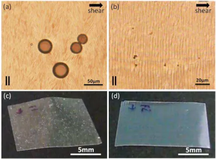
Macroscopically, it was possible to notice differences in the homogeneity of the films obtained by
the two suppliers, as can be seen in the films’ pictures Fig 9c and d. From the POM image of the films
prepared from solutions of HPC from the supplier Sigma-Aldrich, Figure 3.1(a), it is possible to notice
that some bubbles were formed and in the film’s picture (Figure 3.1(c)) the macroscopic aggregates are evident. On the contrary, films prepared from solutions of HPC from the supplier Alfa-Aesar are much more uniform, as indicated by Figures 3.1(b) and 3.1(c).
Figure 3.1 – POM images of films of HPC from the supplier (a) Sigma Aldrich and (b) Alfa Aesar prepared from
aqueous solutions of 60% (w/w) with parallel polarizers and the corresponding photographs of (c) Sigma Aldrich and (d) Alfa Aesar HPC films. The shear direction is indicated with an arrow. || indicates the polarizers are
17
Also, it was noticed that for the same speed of casting, HPC from the different suppliers
originated films with different thicknesses (ranging from 30μm to 90μm). Specifically, solutions of HPC
from Sigma-Aldrich led to films with higher thicknesses. This is consistent with the fact that HPC from this supplier presents a higher viscosity (𝜂 = 125𝑐𝑝𝑠) than the one acquired from Alfa-Aesar (𝜂 =
89𝑐𝑝𝑠), despite the average molecular weight given by the suppliers being the same.
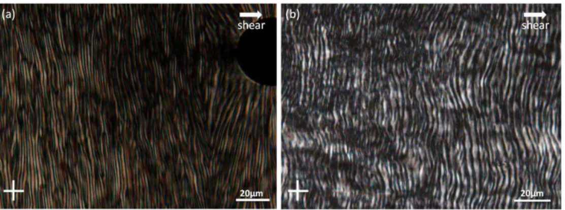
From the POM images of the surface of anisotropic HPC films, taken between cross-polarizers, a periodicity in the form of gratings was observed along the direction perpendicular to shear, Figures 3.2(a) and (b). After the application of shear, films are left to dry at room temperature. During this process of evaporation the density of mesogenic fragments increases near the top surface given rise to increased orientational order. Since the dimensions of the bottom surface (in contact with the substrate) are fixed and, the increase in order leads to an elongation at the surface in the direction parallel to the shear, the top surface buckles, forming the grooves or gratings, which are locked in the films after the complete evaporation of solvent.[27]
According to the literature, for HPC films, casted from identical lyotropic liquid crystalline solutions, the average distance between grooves is in the order of 3.1±0.3μm [28]. Using the software ImageJ, we measured this parameter for our samples and the values obtained were: 1.8±0.4μm and 3.3±0.7μm for Sigma-Aldrich and Alfa Aesar HPC samples, respectively. As we can see, the measurements for Sigma Aldrich samples are significantly lower than the reference values. Godinho et al. [27] showed that in general the formation of grooves in the HPC anisotropic films is imposed by the shear rate and polymer concentration on the precursor solution. Bearing in mind that the shear rate and concentration of precursor solution are both the same for each HPC used one can only assumed that the average molecular weight of this two HPC sources is not the same. Despite the suppliers presented the same
M
̅
w, two distinct values of viscosity, obtained in the experimental same conditions, are given.Figure 3.2 - Transmission polarizing optical microscopy images, taken between crossed polarizers of films of
HPC from the suppliers (a) Sigma Aldrich and (b) Alfa Aesar, prepared from aqueous solutions of 60% (w/w) and shear-casted with a Gardner knife.
Cellulose Nanorods in Liquid Crystalline Elastomers for Improved Actuators
18
From the observation of this table one can see that values from films of HPC from Alfa-Aesar are in good agreement with the ones found in literature [29], however the same was not observed for the films produced from HPC from Sigma Aldrich. For this later source the values, for most of the parameters studied, are one order of magnitude lower than the values found in literature and obtained in this work by films of HPC from the different supplier.
From table 3.1 it can be seen that all films, prepared from anisotropic solutions, showed a higher Young modulus and ultimate tensile strength along the casting direction (Par). The flow induced in these liquid crystalline solutions under the shear stress leads confer a molecular orientation, which results in improved mechanical properties in the direction parallel to the shear.
It is well known the tight relationship between structure and properties in all the materials. According to POM image (in Figures 3.1(a)) and macroscopic appearance (Figure 3.1(c)), samples prepared from Sigma-Aldrich presented some aggregates and major defects. All of this led to films with poor mechanical properties, when compared with the ones prepared from the other source. Recalling the inhomogeneities previously referred, the tensile tests were always performed in different
regions of the sample. However, in average, the values obtained for the Young’s Modulus and for the
ultimate tensile strength were found to be much lower than the ones measured for HPC films produced from Alfa-Aesar.
Table 3.1– Young’s modulus (E), tensile stress (UTS) and strain deformation (ε) of the films prepared from an
HPC 60% (w/w) water liquid-crystalline solution. Par and Per means that the mechanical stress-strain
measurements were performed along the parallel and the transverse directions to the shear casting direction, respectively
* sample did not fracture
The free surface of HPC solid films was exposed to water vapour and the presence of the vapour leads to a local decrease of the order parameter. Simultaneously is expected that the, during the application of moisture, water molecules will occupy the space between cellulosic chains, which leads to an increase of the thickness of the rod-like fragments. As a consequence, the film’s free surface will
suffer an expansion in the direction perpendicular to the director. Because of that, when the stimulus is applied, samples will bend around an axis parallel to the shear direction, with the free surface on the outside, as schematic represented in Figure 3.3.
Figure 3.3 - Scheme of a HPC film’s free surface (contact with air) bending when exposed to moisture.
Supplier E(MPa) UTS(MPa) ɛ (%)
Par. Per. Par. Per. Par. Per.
Alfa-Aesar 254±18 154±24 18±2 8±1 39±6 64±22
Sigma-Aldrich 66±5 52±2 9±2 2±1 60±5 *
19
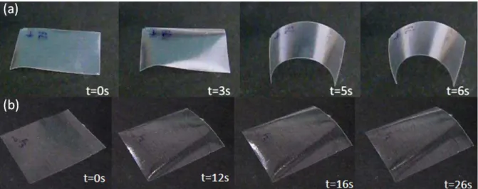
Interestingly, the two samples behaved differently when exposed to humidity. While Alfa HPC samples showed a correct dynamics of the bending (according to previous works) [30] as can be seen in Figure 3.4(a), Sigma HPC samples showed an anomalous movement, bending perpendicularly to the shear direction. Also, the response times (6 seconds vs. 26 seconds) were much slower for the latter ones, as it can be seen from images in Figure 3.4(b).
Compared to previous results, where the maximum bending of the free surface of a film with 30
m was achieved in 8 seconds [30], by decreasing the thickness to 22 μm we were able to accomplish a faster response of about 6 seconds, with the films prepared from HPC solutions of Alfa-Aesar. The unbending time for this sample was approximately 7 seconds, one second lower than the one reported in the literature [30]. Regarding the other sample, the unbending time goes up to 10 seconds.
As the purpose of this work is to optimize the behaviour of the material as an actuator, it was
decided to carry on the films’ preparation with the HPC solutions from Alfa-Aesar, which had the best properties. Nevertheless, it is important to understand the divergence of behaviours between the two batches of HPC. Despite of having the same average molecular weight, according to the suppliers, the two batches presented a very different viscosity. So one can expect the degree of substitution and/or molar substitution of hydroxypropyl groups per anydroglucose unit of cellulose to be different in each HPC source. In fact, the determination of these two parameters by 1H NMR, showed that the average
degree and molar substitution is 1.6 and 4.4 for HPC from Alfa Aesar supplier and 1.8 and 6.0 to HPC from Sigma-Aldrich, respectively, with the substitutional groups attached to different parts of the chain. The detailed determination of the parameters may be consulted in Supplementary Materials – section 6.5. A low DS and high MS can be interpreted as a non-uniform substitution of the cellulosic chain and one can expect that this irregularity would be translated at both micro and nano scale. [31]
Figure 3.4 – Series of video frames showing the bending of the top surface of free standing films of HPC from
Cellulose Nanorods in Liquid Crystalline Elastomers for Improved Actuators
20
3.1.2.Alfa Aesar HPC as Matrix
The x-ray diffractogram obtained for the neat HPC film (from Alfa Aesar) is shown on Figure 3.5. The diffractogram obtained is in good agreement with the one described in the literature for HPC films [32], with the characteristic peaks showing evidence of the HPC major reflections at 2𝜃 = 8.03° and
2𝜃 = 19.82°.
The interplanar spacing was calculated, using Bragg’s Law (equation 3.1):
𝜆 = 2𝑑 sin 𝜃
(3.1)where
𝜆
is the wavelength of incident x-rays (𝜆
=1.5406 Å for the experimental setup used),𝑑
isthe interplanar spacing and
𝜃
is the diffraction angle (Bragg Angle). Applying equation 3.1 to the angle corresponding to the (100) plane, the interplanar spacing was calculated to be approximately 1.694 nm.Based on SEM images (Figure 3.6), a layered structure parallel to the films surface can be
observed and also a periodic reminiscent “pins” from a structure, which exists in between the layers.
The spacing between the layers observed is of the order of microns.
Figure 3.6 - SEM pictures of the cross section of the sheared HPC films. A layered structure parallel to the films surface can be observed with periodic spacing in the range of microns.
Figure 3.5 - XRD diffractogram for a film of Alfa Aesar’s
21
In order to understand the influence of the film thickness in the response time, the following was done: films with different thicknesses were produced, using the adaptation developed within this work, which consists in combining different weights on the top of the Gardner casting Knife during the shear casting and also by using two different types of substrates (glass and Parafilm).
For the purpose of the actuators, we only had focus on the films’ free surface response (Table 3.2), overlooking the surface that was attached to the substrate – the bottom surface. This option lies in the fact that the bottom surface and the free (top) surface have a slightly different behaviour when the water vapour stimulus is applied. Despite the fact that identical bending and unbending response times are obtained [8], the amplitude of the movement is more evident on the top surface than in the bottom. This bottom surface is not so well unravel but one can expected that is less ordered than the top surface, since there is no evaporation of solvent on this bottom surface during shear.
Table 3.2 – Response times for the bending and unbending of
free standing HPC films’ top surface with different thicknesses
Thickness (μm)
Response time (s) Bending Unbending
11.3±1.9 7.0±0.3 3.0±0.3 21.1±1.9 7.0±0.3 6.0±0.3 22.2±3.7 6.0±0.3 7.0±0.3
Analyzing the results from Table 3.2, we easily understand that the thinner film has a relatively faster response, especially for unbending. However, thinner films are really difficult to work with, especially during the process of assembly of the device. Also, when the stimulus is applied, these samples tend to saturate much faster, leading to a local dissolution of the sample.
For these reasons, an intermediate thickness was chosen. One must keep in mind that this new chosen film’s thickness is lower than the one of the films described in the literature [8], which means, that the response time of our system was improved. Despite the two thicker films having identical thickness, these samples were produced in different substrates, as further described in Supplementary Materials – section 6.2.
3.2. NCC Filler
Nanocrystalline cellulose was chemically obtained via acid hydrolysis of commercial microcrystalline cellulose, as described above. Our intention was to use the NCC as reinforcement in HPC films, to achieve a stimuli-responsive material with improved mechanical properties, but mainly improved bending/unbending response times upon stimulus.
Cellulose Nanorods in Liquid Crystalline Elastomers for Improved Actuators
22
In Figure 3.7 it can be seen the X-Ray diffractogram of a thin film of NCC and its source microcellulose (MCC). This figure shows the same diffraction features for both cellulose materials as the ones observed for semicrystalline cellulose type I (also referred to as native cellulose), which is
corroborated by the characteristic peaks at 2θ=14.7°, 16.8° and 22.7° corresponding to the 11̅0, 110 and 200 crystallographic planes of cellulose type I, respectively.
Figure 3.7 – X-Ray diffractograms of the pure MCC source (Avicel) and a thin film obtained from the synthesised
NCCs.
The crystallinity index (𝐼𝐶), which allows comparisons between curves in Figure 3.7, was obtained using the method described in [33]:
𝐼
𝑐=
𝐼
002𝐼
− 𝐼
𝑚𝑖𝑛002
× 100
(3.2)where 𝐼002 and 𝐼𝑚𝑖𝑛 represent the crystalline (maximum intensity at a 2θ angle between 21° and 23°) and the amorphous (minimum intensity at 2θ between 18° and 20°) counterparts, respectively.
The crystalline size 𝐷ℎ𝑘𝑙 was determined using the Scherrer equation [34]:
𝐷
ℎ𝑘𝑙=
𝛽 cos(𝜃)
0.9 × 𝜆
(3.3)where 𝜆 represents the X-Ray radiation wavelength, 𝛽 the Full Width at a Half Maximum (FWHM) of the diffraction peak and 𝜃 the Bragg angle.
Solid films prepared from NCC and MCC solutions were also studied. Crystallinity index and crystallite size are summarized in table 3.3. As expected, there was a significant increase in the crystallinity of the NCC film when compared to the source (MCC). This is related to the removal of the amorphous parts of the cellulose. Regarding the crystallite sizes, the NCC film has slightly smaller crystallites when compared to MCC. These results indicate the successful preparation of NCC by acid hydrolysis of microcellulose.
Table 3.3 - Crystallite size and crystallinity index of the NCC film and comparison with the MCC source
2θ (𝑰𝟎𝟎𝟐) 𝑰𝒄 (%) 𝑫𝒉𝒌𝒍 (nm)
Avicel (MCC) 22.56 76.72 5.39