F
ACULDADE DEE
NGENHARIA DAU
NIVERSIDADE DOP
ORTOAerial Multi-hop Sensor Networks
Luis Ramos Pinto
Programa Doutoral em Engenharia Electrotécnica e de Computadores Co-advisor: Prof. Doutor Luís Miguel Pinho de Almeida
Co-advisor: Prof. Doutor Anthony Rowe
May, 2018
The thesis was also submitted to Carnegie Mellon University, Pittsburgh, USA, in partial fulfillment of the requirements for the Doctoral degree in Electrical and Computer Engineering. The work was supported through the CMU|Portugal dual-degree doctoral program.
Aerial Multi-hop Sensor Networks
Luis Ramos Pinto
Programa Doutoral em Engenharia Electrotécnica e de Computadores
Dissertation submitted in partial fulfilment of the requirements for the
degree of Doctor of Philosophy in Electrical and Computer Engineering at
the Faculty of Engineering, University of Porto
Approved by:
Co-advisor: Prof. Anthony Rowe, PhD Referee: Prof. Pedro Ferreira do Souto, PhD
Referee: Prof. Mário Jorge Rodrigues de Sousa, PhD Referee: Prof. Bruno Sinopoli, PhD
Referee: Prof. Patrick Tague, PhD April 10, 2018
To my family,
Mafalda
and my daughters
À minha família,
à Mafalda
e às minhas filhas
vAcknowledgements
I would like to thank my advisors, Luis Almeida and Anthony Rowe, for their sup-port. Their guidance and knowledge allowed me to pursue my degree of Doctorate in Philosophy revolving along a topic I truly enjoyed. They have supported, encouraged and motivated me to work hard along these last years and allowed me to meet other researchers and their work.
I would like to thank the co-authors of my main publications for their ideas and hard work namely Luís Oliveira, André Moreira, Sidney Carvalho and Hassan Alizadeh. I would like to thank the defense committee members for their time and input, namely professors Patrick Tague and Bruno Sinopoli from CMU, and professors Mario Sousa and Pedro Souto from FEUP. I cannot express enough gratitude towards the CMU Portu-gal PhD program, namely the staff for their kindness, and the financial support provided by the Fundação para a Ciência e a Tecnologia (Portuguese Foundation of Science and Technology) under grant SFRH/BD/51630/2011.
I would like to extend my gratitude to my colleagues and friends that I met both at CMU and at FEUP; they have provided me such good times and made my time during the PhD absolutely great. Lastly, I would like to thank my family, specially my beloved wife that motivated me 100% to start the PhD. Along with my daughters, they inspire me and make me the happiest person alive.
Abstract
Unmanned Aerial Vehicles (UAVs) recently enabled a myriad of new applications span-ning domains from personal entertainment and industrial inspection, to criminal surveil-lance and forest monitoring. A combination of sensor collection, wireless communi-cation and path planning between multiple distributed agents is the natural way to support applications. Several small UAVs working collaboratively can rapidly provide extended reach, at low cost, and efficiently stream sensor information to operators on a ground station. A significant amount of previous work has addressed each of these topics independently, but in this dissertation we propose a holistic approach for joint co-ordination of networking and topology (placement of mobile nodes). Our thesis is that this approach improves user-interactive control of UAVs for live-streaming applications in terms of throughput, delay and reliability.
In order to defend these claims, this dissertation begins by experimentally evaluating and modeling the wireless link between two UAVs, under different conditions. Due to limited link range, and the need for wide-area operation, the model is extended to encompass a multi-hop topology. We show that the performance of such networks using COTS devices is typically poor, and solutions must rely on coordination of network protocol and topology, simultaneously.
At the network layer, we introduce a novel Time-division Multiple Access (TDMA) scheme called Distributed Variable Slot Protocol that relies on adaptive slot-length. We prove its convergence as well as its meliorated performance experimentally validated, namely 50% higher packet delivery. In terms of network topology, we show that without node placement control overall performance of the network is severely penalized, due to natural link asymmetries. We propose a novel protocol, named Dynamic Relay
ment, that is able to do both online link quality model-estimation and in a distributed fashion decide the best location for each network node, increasing throughput by 300%. Finally, we demonstrate the end-to-end system in a multi-vehicle monitoring mis-sion. We show that coordination of multiple UAVs increases the sensor sampling rate up to 7 times in wide areas when compared to a naive approach. This work considers environmental constraints such as wind, as well as the intrinsic limitations of the vehi-cles such as maximum acceleration.
Keywords: 802.11, ad hoc networks, channel models, monitoring, relay placement, relay
networks, time division multiple access, unmanned aerial vehicle, wireless communica-tion.
Resumo
Avanços recentes em veículos aéreos não tripulados (UAVs) têm vindo a permitir uma miríade de novas aplicações, espalhando-se por domínios do entretenimento pessoal à inspeção industrial, da vigilância criminal à monitorização florestal. Uma combinação de sensores, comunicação sem fios e planeamento de rotas entre múltiplos agentes dis-tribuídos é a forma natural de realizar tais aplicações. Vários UAVs trabalhando colabo-rativamente podem rapidamente fornecer maior alcance, a baixo custo, e eficientemente transmitir ao vivo informação sensorial para operadores numa estação base, no solo. Uma parte significativa do estado-de-arte relacionado visa cada um destes tópicos in-dependentemente, por isso nós nesta dissertação propomos uma abordagem holística para uma coordenação conjunta do protocolo da rede e da topologia (colocação de nós). A nossa tese é que esta abordagem melhora a interactividade do utilizador no controlo de UAVs em aplicações de transmissão ao vivo em termos de velocidade, latência e confiabilidade.
De forma a defender esta tese, esta dissertação começa por experimentalmente avaliar e modelar o canal sem fio entre dois UAVs, sob diferentes condições. Devido ao limitado alcance da ligação, e à necessidade de operação a larga escala, o modelo é completado considerando para isso topologias multi-salto. Mostramos que o desempenho destas redes usando dispositivos COTS é tipicamente pobre, e que pode ser melhorado com uma coordenação simultânea da rede e da topologia.
A nível da rede, propomos um novo sistema de melhoria da comunicação baseado em TDMA (Acesso Múltiplo por Divisão de Tempo). Este novo protocolo chamado Distributed Variable Slots Protocol funciona com base na adaptação do tamanho das slots atribuídas a cada transmissor. A sua convergência é provada, assim como validada experimentalmente no desempenho melhorado do sistema, nomeadamente 50% mais
entrega de pacotes. A nível da topologia, mostramos que sem controlo de posiciona-mento de nós o desempenho da rede é severamente penalizado devido a assimetrias naturais dos links. Propomos um novo protocolo, chamado Dynamic Relay Placement que é capaz de estimar a qualidade das ligações em tempo-real assim como de forma distribuída decidir a melhor localização para cada um dos nós da rede, aumentando as taxas de transferência em 300%.
Para finalizar, desenhamos uma missão de monitorização multi-veículo. Mostramos que com uma cordenação adequada de vários veiculos aumenta em 7 vezes a taxa de sensorização de áreas extensas quando comparada com uma abordagem mais simples. Este trabalho considera restrições ambientais tais como o vento, assim como as limi-tações intrínsecas dos veículos tais como aceleração máxima.
Palavras-chave: 802.11, ad hoc, modelo canal, monitorização, redes sem fio, repetidores,
Table of Contents
Dedication v
Acknowledgements vii
Abstract ix
Resumo xi
Table of Contents xiii
List of Tables xvii
List of Figures xviii
Notation xxi
Technical abbreviations and acronyms . . . xxi
Units . . . xxii
Math Expressions . . . xxii
Definitions . . . xxiii
Other . . . xxiv
1 Introduction 1 1.1 Unmanned Aerial Vehicles . . . 1
1.2 Context . . . 2
1.3 Team of UAVs . . . 3
1.4 Applications . . . 4
1.5 System Challenges . . . 7
1.6 Vision and thesis . . . 10
1.7 Goals . . . 11
1.8 Contributions . . . 12
1.9 Organization . . . 14
2 Background 15 2.1 UAV . . . 15
2.2 UAV Wireless Sensor Networks . . . 17
2.3 Network Performance . . . 18
2.4 Medium Access . . . 21
2.5 Relay Placement . . . 24
2.6 Applications . . . 25
3 Building an Aerial Multi-hop Network 31 3.1 Problem Statement . . . 32
3.2 Link Layer – Experiments . . . 33
3.3 Link Layer – Model . . . 38
3.4 Network – Model . . . 40
3.5 Network – Experiments . . . 45
3.6 Multi-hop Network Summary . . . 49
4 Self-Synchronized Network TDMA 51 4.1 Synchronization Method . . . 52
TABLE OF CONTENTS xv
4.3 Synchronization Summary . . . 58
5 Dynamic Slot-length for TDMA 59 5.1 Problem Statement . . . 60
5.2 A Variable Slot-length TDMA Solution . . . 62
5.3 Protocol . . . 66
5.4 Convergence . . . 66
5.5 Worst Case Delay . . . 72
5.6 Evaluation . . . 75
5.7 Dynamic Slot-length Summary . . . 81
6 Relay Placement 83 6.1 Problem Statement . . . 84
6.2 Optimal Relay Placement . . . 86
6.3 Dynamic Relay Placement (DRP) Protocol . . . 88
6.4 Experimental results . . . 90
6.5 Relay Placement Summary . . . 94
7 Aerial Monitoring 95 7.1 System description . . . 96
7.2 Optimal Trajectories and Frame-rate . . . 102
7.3 Distributed Formation Control . . . 107
7.4 Simulation Results . . . 108
7.5 Monitoring Summary . . . 113
8 Drones Software Architecture 115 8.1 Navigation Data, Actuator and Flight Control . . . 115
8.2 GPS and Autonomous Flight . . . 117
8.4 Communications . . . 119
9 Conclusion 125 9.1 Thesis Validation . . . 125
9.2 Future Work . . . 127
Bibliography 131 A Channel Assessment Model 137 B Drone-RK API 141 B.1 Navdata . . . 141 B.2 GPS . . . 142 B.3 Flight Control . . . 143 B.4 Autonomous Flight . . . 144 B.5 Packet Manager . . . 145 B.6 PDR . . . 146 B.7 TDMA . . . 146 B.8 Video . . . 147 B.9 Image Processing . . . 148 B.10 Actuator . . . 148 B.11 AR Config . . . 148 B.12 Keyboard . . . 149 B.13 Utils . . . 149
List of Tables
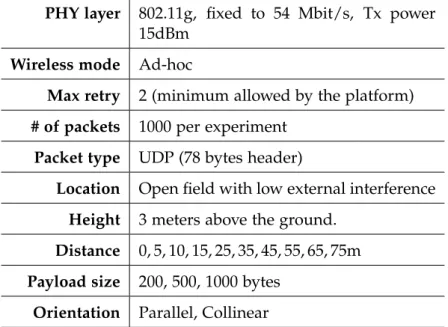
3.1 Experiment setup for the two AR Drone 2.0 vehicles in the single-link channel characterization . . . 34 3.2 Parameters of the PDR model for different conditions . . . 39 3.3 Experiment set-up for the AR Drone 2.0 vehicles on the multi hop network
characterization. . . 46 7.1 Summary of UAV motion equations . . . 100 7.2 Simulation Setup for the Video-monitoring application. . . 109
1.1 Parrot AR Drone 2.0 quadrotor is controlled by a smartphone. . . 2
1.2 DJI Mavic Pro does obstacle avoidance and allows insertion of external cameras. 2 1.3 Eachine E013 is a low-cost micro quadrotor equipped with camera and FPV headset. . . 3
1.4 Intel Aero research platform comes with a vast set of external sensors. . . 3
1.5 A quadrotor swarm and communication links (red dashed-lines). . . 4
1.6 LeddarOne is a LIDAR sensor designed for small UAVs. . . 4
1.7 Drone view of Pedrogão, Portugal . . . 5
1.8 Drone view of Santa Rosa, California . . . 5
1.9 Indian authorities are considering drones for crowd control. . . 5
1.10 Examples of large-scale applications for drone swarms . . . 6
1.11 List of challenges designing aerial multi-hop sensor networks . . . 7
1.12 Vision of aerial multi-hop sensor network . . . 11
2.1 Diagram of a multirotor with four rotors . . . 15
2.2 A UAV wireless sensor network . . . 17
2.3 TDMA allows each node to send packets in their own slots. . . 22
3.1 AR Drone 2.0 platform, a common COTS quadrotor, used for the experiments. 33 3.2 Typical PDR value over time. It mimics a Bernoulli experiment. . . 35
List of Figures xix
3.3 PDR versus distance on different conditions. . . 36
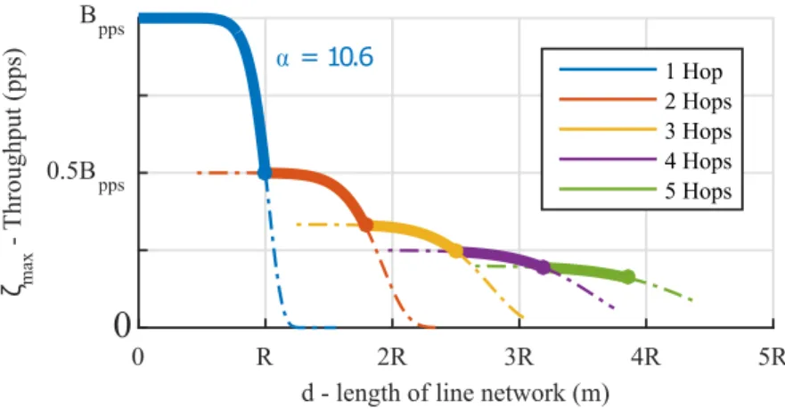
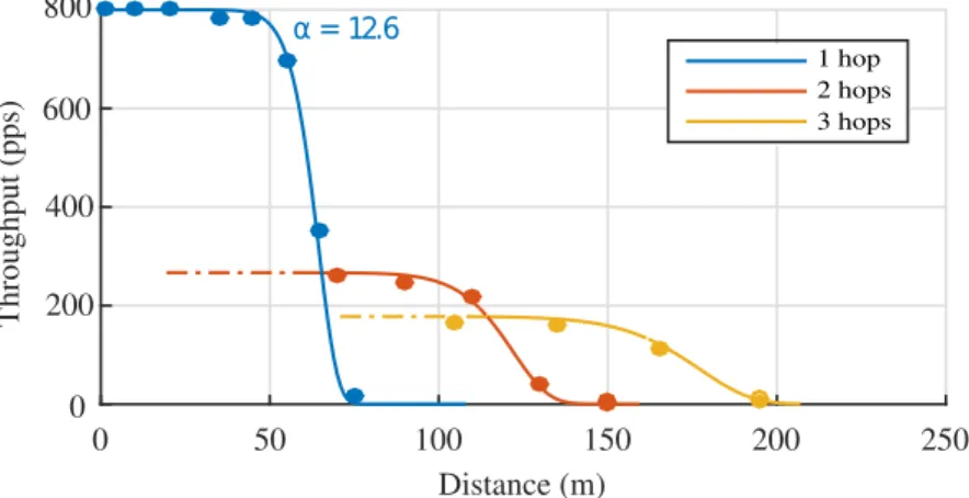
3.4 Maximum network throughput as function of distance . . . 46
3.5 Packet traces captured by a monitor node, using Wireshark(Wireshark, 2016) 48 3.6 Throughput at different end-to-end network lengths . . . 48
4.1 Round period time is obtained from the epoch time via modulo operation . 53 4.2 Defining a TDMA slot and respective boundaries . . . 53
4.3 Node with slot ID 3 estimates boundaries of slots ID 1 and ID 2 . . . 55
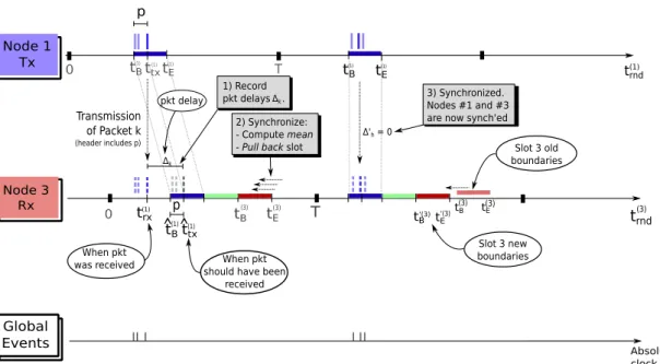
4.4 Illustration of TDMA self-synchronization mechanism taking place . . . 57
4.5 Example of TDMA self-synchronization mechanism taking place . . . 58
5.1 Multi-hop Line Network model . . . 60
5.2 Inefficiencies using CSMA . . . 62
5.3 Inefficiencies under TDMA when all time slots are of equal length . . . 63
5.4 Concept of DVSP where each slot has different length . . . 63
5.5 Handshake diagram of Distributed Variable Slot-length Protocol (DVSP). . . 67
5.6 Example of slot length convergence in a network with four slots . . . 71
5.7 DVSP convergence with 4 hops . . . 73
5.8 DVSP convergence with 6 hops . . . 73
5.9 DVSP convergence with 10 hops . . . 74
5.10 DVSP convergence with 12 hops . . . 74
5.11 Different topologies used during the experiments . . . 76
5.12 Histogram of measured end-to-end delay . . . 78
5.13 Histogram of measured end-to-end packet delivery ratio . . . 79
5.14 Histogram of measured end-to-end goodput . . . 80
5.15 Snapshot of the video stream at the sink . . . 81
6.1 Multi-hop line network model . . . 84
6.3 Example of optimal solution for the relay position problem . . . 87
6.4 Optimal PDR and relay placement versus network end-to-end distance . . . 88
6.5 DRP initial state. Relay is 10m away from BS. . . 90
6.6 DRP state when relay is 23m away from BS. . . 90
6.7 DRP state when relay is 43m away from BS. Estimation matches ground truth. 90 6.8 DRP final state. Relay estimated the optimal location at 57.8m from the Source. 90 6.9 Experiment layout of the UAVs and computer base station . . . 91
6.10 Experimental packet delivery ratio measurements . . . 93
6.11 Video stream snapshot with relay positioned at two distinct locations . . . . 93
6.12 End-to-end throughput at different relay positions . . . 94
7.1 Overview of the video-monitoring application system . . . 97
7.2 Model of the Area of Interest . . . 98
7.3 Networking and topology models . . . 101
7.4 Proposed optimal trajectory for the UAVs (even case) . . . 104
7.5 Proposed optimal trajectory for the UAVs (odd case) . . . 104
7.6 Maximum frame rate vs number of UAVs (i) . . . 110
7.7 Maximum frame rate vs number of UAVs (ii) . . . 111
7.8 Maximum frame rate vs number of UAVs (iii) . . . 112
8.1 Drone-RK software is comprised of several modules . . . 116
8.2 Piksi GPS Basestation . . . 118
8.3 Piksi GPS on a drone . . . 118
8.4 Application layer working diagram . . . 120
8.5 Packet Manager (PM) layer working diagram . . . 121
8.6 TDMA layer working diagram . . . 122
Notation
Technical abbreviations and acronyms
• 3D: three-dimensional• AL: application layer • AoI: area of interest • BS: base station
• ID: identification number • COTS: commercial of the shelf • CSMA/CA: carrier sense multiple
ac-cess with collision avoidance
• DVSP: distributed variable slot-length protocol
• DRP: dynamic relay placement • E2E: end-to-end
• FoV: field of view
• FPV: first person view
• GPS: global positioning system • GS: ground station; same as BS • LIDAR: light detection and ranging • MAC: medium access control • OSI: open systems interconnection • PID: proportional, integrator and
dif-ferential controller
• PDR: packet delivery ratio • PDU: protocol data unit
• PHY: physical layer of the OSI model • PM: packet manager
• PoI: point of interest xxi
• QoS: quality-of-service
• RA-TDMA: reconfigurable and adap-tive TDMA
• RCVM: remote control and video-monitoring
• RMSE: root mean square error • Rx: receiver
• SI: international system of units
• SNR: signal-to-noise ratio
• TCP: transmission control protocol • Tx: transmitter
• TDMA: time-division multiple access • UAV: unmanned aerial vehicle • UDP: user datagram protocol • wc: worst case
• WSN: wireless sensor network
Units
• bit/s: bps, bits per second • B/s: bytes per second • dBm: power decibel
• k: kilo multiplier (a thousand) • M: mega multiplier (a million) • pps: packets per second
Math Expressions
Unless explicitly stated, referred quantities use SI units. • b·c: floor operator
• d·e: ceiling operator
• frac(·): fractional part of a number • Π - the product operator
• R: set of real numbers
• R+: set of positive real numbers • R0+: set of non-negative real
DEFINITIONS xxiii • d: network E2E length
• Bi,j: bandwidth from node i to node j
• dwc: worst case delay
• dtx: transmission delay
• dw: waiting delay
• h: number of hops • iff: if and only if • li: length of link i
• pl: link PDR
• pn: network E2E PDR
• RMSEe: exponential model’s RMSE
• RMSEσ: sigmoid model’s RMSE
• si: time duration of TDMA slot
at-tributed to node i • T: TDMA round period • ζl: link throughput
• ζn: network E2E throughput
• ζmax: maximum ζn, when using
opti-mal number of relays.
Definitions
• affine: functions of the form
f(x1, ..., xn) = A1x1+...+Anxn+b
• bandwidth: maximum throughput a node is capable of achieving
• goodput: similar to throughput where only useful payload is consid-ered as transferred data.
• sink: in sensor networks, it is the
node receiving the main flow of data from all sensor-nodes.
• PDR: percentage of packets success-fully transferred from source to des-tination.
• throughput: speed of data being suc-cessfully transferred from source to destination.
Other
• aka: also known as
• CMU-ECE: Carnegie Mellon Univer-sity, Electrical and Computer Engi-neering (Dept.)
• cf.: latin confer/conferatur, both mean-ing "compare"
• DEEC: Departamento de Engenharia Eletrotécnica e Computadores
• e.g.: latin exempli gratia, meaning "for example"
• et al.: latin et alia, meaning "and oth-ers"
• FEUP: Faculdade Engenharia da Uni-versidade do Porto
• i.e.: latin id est, meaning "that is" • vs.: versus
Chapter 1
Introduction
1.1 Unmanned Aerial Vehicles
An Unmanned Aerial Vehicle (UAV) is an aircraft that is able to fly and be controlled without the presence of a human pilot on board. These vehicles date back as early as the Great War, from balloons to miniatured versions of traditional airplanes. Also around this time, a different category of aerial vehicle – the man-piloted helicopter – made its debut. It rapidly became a resourceful vehicle due to its ability to take off and land vertically as well as hover. In recent years, improvements in micro electromechanical systems such as inertial sensors and low-cost high-speed micro-controllers have made remotely piloted helicopters increasingly smaller and extremely accessible. Especially in small vehicles, the main throttle rotor with a smaller tail-rotor design was replaced by multiple equally-powered rotors on a single plane. This ends up being a simpler design and producing a more agile vehicle. These vehicles are named multirotors in the literature and commonly known nowadays as drones due to their noise sounding similar to a male bee. Throughout this document we will refer to multirotors as UAVs or drones, since the vast majority of times the terms are interchangeable.
Figure 1.1: Parrot AR Drone 2.0 quadrotor is controlled by a smart-phone.
Figure 1.2: DJI Mavic Pro does obsta-cle avoidance and allows insertion of external cameras.
1.2 Context
Commercial-off-the-shelf (COTS) drones, in particular the four-rotor design known as a quadrotor, have seen their popularity expanded tremendously in the recent years. Agile maneuverability and hovering capabilities at small scales are highly relevant features in urban scenarios, but its popularity can mainly be justified by three others factors.
The first is their simplified (remote) user control. Even without aeronautical knowl-edge or previous flight-time, users can rapidly gain skills, and fly smoothly in a matter of hours. Vehicle stabilization is typically guaranteed by a local automatic controller. This means the vehicle maintains vertical and horizontal position, as well as pose, even without providing user input. Primarily, drones resort to accelerometers, compasses and gyroscopes for navigation; precision may be enhanced by encompassing ultrasound sensors and barometers to maintain vertical position, and by cameras running optical flow algorithms for the horizontal position. UAVs such as Parrot (2012) AR.Drone 2.0 (cf. Figure 1.1) allow the operator to use a smartphone and its embedded touch interface to move the UAV forward/backwards or left/right with one finger, and simultaneously spin or move up/down the vehicle with another finger.
The second driver for drone popularity is the fact that these devices are now carry-ing high-quality cameras on-board. Inclusively, high-end COTS drones (eg. DJI (2017)
1.3. TEAM OF UAVS 3 Mavic Pro, in Figure 1.2) allow the operator to insert a professional camera that records on-board movie-grade video from the surroundings; some include additional camera stabilizers (a gimbal). For flight control, a low-resolution, low-delay alternative camera is included that streams video to the operator on the ground.
The third justification is simply their reduced price. Low-end drones without cam-eras are available for as low as USD$20, and have cheap replacement parts on-sale. Going up the scale, depending on the added features, we find racing drones with First Person View (FPV) head-screens for USD$70, such as the Banggood (2017) Eachine E013 (cf. Figure 1.3). Research drones that include GPS and 3D cameras such as Intel (2017) Aero are recently available for USD$1000 (cf. Figure 1.4).
1.3 Team of UAVs
Drones typically have two communication flows. Upstream, from user to drone, for control and downstream, from drone to user, for acknowledgment and sensor data. Currently, the dominant data path is from user to drone, but this is rapidly changing with the advent of high resolution cameras and other external sensors. Streaming from the environment opens a new course of operation, namely using such flying devices
Figure 1.3: Eachine E013 is a low-cost micro quadrotor equipped with cam-era and FPV headset.
Figure 1.4: Intel Aero research plat-form comes with a vast set of external sensors.
as mobile and agile sensors in a cooperative swarm (cf. Figure 1.5). A network that considers all of these aspects is what we define as an aerial multi-hop sensor network. The four main requirements to create a UAV team are 1) (on-board) sensors to collect data, 2) communication for cooperation and sensor streaming, 3) computational power to process data, 4) world-perception for obstacle avoidance and flight-formation. Due to technology advances, it is now possible to equip drones to fulfill these requirements. A good example is the Intel (2017) Aero with a 8 megapixel camera, a 802.11ac WiFi card (that goes up to 3466.8Mb/s), a Intel Atom quad-core processor with 2.56Ghz of max-imum clock-speed and 4GB of RAM, and it also includes a depth-camera for obstacle avoidance (Intel RealSense) as well as GPS. Other companies also include ultrasound (eg. Mavic Pro) and LIDAR technologies in their platforms (eg. Tech (2017) LeddarOne, shown in Figure 1.6) for improved obstacle avoidance;
1.4 Applications
Small and semi-autonomous multirotor aircraft is enabling a myriad of new applica-tions. To date the focus has been primarily on single devices and not swarms. Compa-nies have found applications in advertising due to the relative low investment cost and interesting bird-eye perspective. Media crews are now able to report events such as the
Figure 1.5: A quadrotor swarm and communication links (red dashed-lines).
Figure 1.6: LeddarOne is a LIDAR sen-sor designed for small UAVs.
1.4. APPLICATIONS 5 aftermath devastation caused by wild forest fires on a remarkably unfamiliar way such as in Santa Rosa, California (cf. Figure 1.8, Fortune (2017)) and Pedrogão, Portugal (cf. Figure 1.7, SIC (2017)). We now find multirotors also being used by law enforcement agencies to track people and their movements during crowded and chaotic events (cf. Figure 1.9, CNN (2015)).
On a different context, UAVs are an excellent option for monitoring, inspection and surveillance of large-scale facilities, such as industrial plants or large factories, and even big infrastructures such as bridges and buildings. On one hand, sites such as high chimneys, electrical poles, large petrol tanks, pillars and long pipelines typically de-mand labor-intensive, dangerous and expensive manual inspections. On the other hand, drones are disposable and can become remote eyes on the ground; a swarm of multiple ve-hicles can inclusively increase the speed of such work many folds. Search-and-rescue in areas affected by disasters can benefit tremendously from remotely operated
multi-Figure 1.7: Pedrogão, Portugal Figure 1.8: Santa Rosa, California
Figure 1.10: Swarms of drones can be used for monitoring and inspection of large-scale facilities. Search-and-rescue is another application.
rotors. Such scenarios, as depicted in Figure 1.10, cannot assume an ubiquitous radio communication infrastructure in place such as cellular, or clear roads for transportation of human-resources. Therefore, it is natural that multirotors taking off vertically and a swarm generating its own ad-hoc network are viewed as potential problem solvers.
All these scenarios have two common requirements. First, they need to collect im-ages, video or other sensor information over large areas. Second, they often need to stream this data live to a base station to support interactive control by an operator. In these scenarios an operator located at a ground station often needs to fine-tune the po-sition of drones and sensors in order to improve sensing resolution in certain areas of interest.
Unfortunately, video streaming on standard WiFi performs poorly, particularly with relays, resulting in long delays and lost frames. Currently, the vast majority of live-stream video from drones, such as the use in FPV systems, uses analog channels, due to its low latency. However, these are not only more susceptible to noise, but also harder to multiplex among several transmitters, as in swarms. Ad-hoc communication between drones may offer a viable alternative compared to infrastructure networks, e.g., cellular,
1.5. SYSTEM CHALLENGES 7 CHAP TER CHAP TER CHAP TER CHAP TER CHAP TER
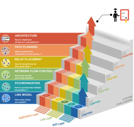
Figure 1.11: List of challenges designing aerial multi-hop sensor networks span across three networking layers, and are covered in the next six chapters.
in terms of availability, reliability and/or cost but such solution will come attached to multiple challenges.
1.5 System Challenges
From potential problem solvers to a fully-fledged system that copes with such scenar-ios, there is a long road of challenges that swarms have to overcome, summarized in the diagram of Figure 1.11. To begin, it is hard to establish a reliable communication link to convey remote sensing information. The wireless medium is well known to be
inherently unreliable. A receiver has to translate an electromagnetic signal into mean-ingful information, the received signal needs to stand above the background noise, (cf. signal to noise ratio – SNR). Such signal is time-variant, dependent on other radio trans-missions taking place in the surroundings (interference), whether these are generated by unknown sources or some other network nodes. Furthermore, on aerial networks it is expected that nodes change both location and pose, continually. This means dis-tance and angle of the receiver-transmitter antennas will vary. It is known the quality of wireless communication, or more precisely, the channel capacity, degrades sharply with distance between receiver (Rx) and transmitter (Tx), and varies with respect to antennas orientation.
Typically in video stream applications, losses are compensated for by automatically changing the physical layer modulation scheme (PHY), lowering the bit rate or using complementary Internet-based technologies, such as TCP/IP, at the cost of a severe and unpredictable impact on delays.
Nevertheless, we know that for a given set of antennas and transmission power, eventually there is a distance above which the SNR will be lower than needed for actual communication no matter the orientation between a sensor node and the operator. The communication link is said to be broken at that point. We will show that assigning UAVs to relay data can fix this condition between far-neighboring nodes, by decreasing the Tx-Rx distance. From top to bottom, this creates a new set of challenges shown in Figure 1.11.
The first challenge regards the optimal number of relays to use. If all nodes operate on the same wireless channel, they will have to share it. Note that typically, wireless cards can only listen to or transmit packets one at the time. Without coordination, too many simultaneous transmitters create interference and packet loss, in consequence. More relays mean shorter Tx-Rx distances, and consequently more reliability. However, more relays imply more elements sharing the medium and less available throughput for
1.5. SYSTEM CHALLENGES 9 each one.
The second challenge regards the actual coordination among UAVs to avoid simul-taneous transmissions. Synchronizing transmissions on a wide distributed, multi-agent, wireless system is inherently a hard problem. To synchronize nodes, clock information needs to be shared. The problem is that on a wide network, especially a not fully con-nected one, information takes several hops and a non-trivial time to travel through the nodes. Associated jitter and delay make clock adjustments imprecise. The challenge is to synchronize tightly enough that simultaneous transmissions are minimized. This first set of challenges is represented by the blue layer of Figure 1.11, and treated in Chapters 3 and 4.
The third and fourth challenges regard the relays placement and their transmission rate. When data is flowing through multiple nodes, a multi-hop network, each interme-diate node is in charge of receiving incoming packets, and retransmitting them at a later moment. When inbound packets arrive at a higher rate than they can leave, we have a backlog problem. Under this condition, packets have to enter a buffer and wait to be delivered. This is one of the major roots of end-to-end delay; if the buffer reaches its limit, it creates losses, too. Unless the channel characteristics of the outbound link are at least as good as those of the inbound link, we can not guarantee that under heavy load, there will be no backlog. Having control of UAVs gives us conditions to change the inbound/outbound link characteristics. On a slower time scale, moving UAVs change links capacity directly at the physical level. The challenge is to measure such capacities (unbalances), and act accordingly. On a faster time scale, deciding the rate of trans-mission at every node changes link utilization at the link level. The challenge here is to measure and react fast enough before the channel changes. These are the core of the challenges on optimizing an aerial multi-hop network. They are represented by the yellow and green middle layer of Figure 1.11, and treated in Chapters 5 and 6.
periodically means sensor data (i.e. video) is being collected and streamed back to a Base Station (BS). The problem is to assign UAV roles to a given team of UAVs. With too many UAVs assigned for sensing and few for relaying, the system can sweep the Area of Interest (AoI) faster than it can deliver data to the BS. In opposition, with plenty of relays and few sensors, the communication backbone from AoI to BS has now potentially more capacity than the effective data the system is generating. Therefore, one challenge is to resolve this tradeoff, and the other is to strategically design trajectories that allow n-sensor UAVs collect data n-times faster than a single one. This last set of challenges is represented by the red layer of Figure 1.11, and treated in Chapter 7.
1.6 Vision and thesis
This dissertation and its underlying research was carried out with the vision that Un-manned Aerial Vehicles (UAVs), in particular multirotors, can become a powerful tool for live (interactive) remote inspection of large-scale structures. Instead of manual, local and labor-intensive inspections, we envision one human operator working together with semi-autonomous UAVs on four stages. Firstly, the operator at a ground Base Station (BS) defines an remote Area-of-interest (AoI) and instructs a group of semi-autonomous sensor-capable UAVs to navigate there; secondly, interactive control of the fine posi-tion and pose of UAVs is initiated to focus on features of interest; concurrently, a live stream of sensor data from the AoI is initiated; finally, the necessary communication backbone is established, by means of a complementary autonomous group of UAVs, linking sensor UAVs to the BS. This vision, illustrated by Figure 1.12, is accompanied with the perception that the current state-of-the-art in UAVs still does not focus enough on solutions for creating and maintaining a reliable network.
We claim that user-interactive coverage and inspection applications resorting to UAVs and without the presence of an external infrastructure need a reliable, long-range,
high-1.7. GOALS 11 AoI SENSOR GS R3 R2 R1 SENSOR
Figure 1.12: Our vision of an aerial multi-hop sensor network, streaming to a base station, resorting to UAVs to relay data.
throughput and low-delay communication backbone properly setup. As a result, this dissertation presents the following thesis:
Joint coordination of network protocol and topology (placement of nodes) will improve user-interactive control of UAVs for streaming applications in terms of through-put, delay and reliability.
1.7 Goals
This dissertation was designed to meet five main goals, namely:
1. Understand in detail a UAV-to-UAV link.
2. Understand in detail a multi-hop network of UAVs.
3. Uncover major issues in these networks when transporting delay-sensitive high-throughput data.
4. Provide a systems solution tailored to swarm operations.
1.8 Contributions
The contributions are organized along two categories: conceptual and technical. Un-der the former, this dissertation introduces several new models and algorithms. First, a new model for packet delivery ratio (PDR) as a function of link length, packet size, and node orientation has been identified; later, extended for multi-hop networks. Then, we present a new algorithm for distributed slot synchronization to optimize TDMA communication. Building from the slot synchronization, we introduce a new algorithm called Dynamic Variable-length Sloted Protocol (DVSP) has been designed, and its own convergence proved. An online, distributed algorithm named dynamic relay placement (DRP) has been designed. It is able to assess the quality of the medium online, and also seek the best location for each relay to achieve maximum network performance. Finally, this dissertation provides and evaluates a new persistent multi-vehicle monitoring algo-rithm with communication constraints. A model is designed that is able to identify the minimum sweeping period of an Area of Interest given UAV and network conditions.
Under technical contributions, this dissertation presents the implementation of the software library for our embedded GNU/Linux drone platform as well as a reference implementation of each algorithm with supporting protocols. It was organized into several modules, each with its own functionality as part of the Drone-RK platform. Drone-RK is a dynamic library written in C that contains 13 main modules, namely: 1) Navdata and 2) GPS to read sensor data; 3) Actuator and 4) Flight Control to send motion commands; 5) ARConfig to setup the vehicle; 6) Autonomous Flight to do way-point flights; 7) TDMA and 8) Packet Manager to provide multi-hop communication and run DVSP protocol; 9) PDR to estimate PDR and run DRP protocol; 10) Video and 11) Image Processing to collect video and process its content; 12) Utils to provide a generic set of tools to all modules; 13) Keyboard to allow user-input. User-level applications are able to dynamically load Drone-RK and easily access these functions.
1.8. CONTRIBUTIONS 13 This dissertation validates by experimentation all concepts referred above, namely validation of link and multi-hop models, DVSP and DRP. Last but not least, a simula-tor was created. It is able to run and test multiple Drone-RK applications in a single machine.
Most of these contributions have been published under the following references: • L. Pinto, A. Moreira, L. Almeida and A. Rowe, "Aerial multi-hop network
char-acterisation using COTS multi-rotors," 2016 IEEE World Conference on Factory Communication Systems (WFCS), Aveiro, 2016, pp. 1-4 – (Pinto et al., 2016a) • L. R. Pinto, L. Oliveira, L. Almeida and A. Rowe, "Extendable Matrix Camera Using
Aerial Networks," 2016 International Conference on Autonomous Robot Systems and Competitions (ICARSC), Braganca, 2016, pp. 181-187 – (Pinto et al., 2016b) • L. R. Pinto, L. Almeida and A. Rowe, "Demo Abstract: Video Streaming in
Multi-hop Aerial Networks," 2017 16th ACM/IEEE International Conference on Infor-mation Processing in Sensor Networks (IPSN), Pittsburgh, PA, 2017, pp. 283-284 – (Pinto et al., 2017c)
• L. R. Pinto, A. Moreira, L. Almeida and A. Rowe, "Characterizing Multihop Aerial Networks of COTS Multirotors," in IEEE Transactions on Industrial Informatics, vol. 13, no. 2, pp. 898-906, April 2017 – (Pinto et al., 2017d)
• L. R. Pinto , L. Almeida and A. Rowe, "Balancing Packet Delivery to Improve End-to-End Multi-hop Aerial Video Streaming," in ROBOT 2017: Third Iberian Robotics Conference. Advances in Intelligent Systems and Computing, Seville, 2017, vol 694 – (Pinto et al., 2017b)
• L. R. Pinto, L. Almeida, H. Alizadeh and A. Rowe, "Aerial Video Stream over Multi-hop Using Adaptive TDMA Slots," 2017 IEEE Real-Time Systems Sympo-sium (RTSS), Paris, 2017, pp. 157-166 – (Pinto et al., 2017a)
1.9 Organization
The remainder of this dissertation is organized as follows. Chapter 2 discusses rele-vant background knowledge for this dissertation. Chapter 3 studies the communication link between two multirotors. Chapter 4 describes an extension to multi-hop operation and the node synchronization problem. We identify the major sources of inefficien-cies on such networks, and we dedicate the following two chapters to solving them. Chapter 5 proposes a new technique based on adaptive TDMA slots to optimize data traffic in the network. Chapter 6 presents a complementary and also novel technique for relay placement to optimize the multi-hop network. An application scenario and its idiosyncrasies are explored in Chapter 7, revolving around coordinated monitoring using several sensor-UAVs. Chapter 8 describes the implementation effort to run the experiments necessary to test all the concepts explored in the other chapters. Chapter 9 summarizes the main conclusions along the mentioned topics, and inclusively revisits initial claims to provide necessary closure. Potential future work is discussed as well.
Chapter 2
Background
In this chapter, we present some background that allows the reader to be acquainted with the topics referred along this dissertation. Furthermore, we include state-of-the-art research work that provided the driving force for this work, by identifying tried solutions and lacunae in the literature.
2.1 UAV
Figure 2.1: Drone with four ro-tors. Propellers rotate in dif-ferent directions to counteract angular acceleration.
UAVs are generally composed by flying chassis and its actuators, sensors , a central processing unit and a bat-tery pack. Figure 2.1 depicts a multirotor with four rotors, the most common design found. To counteract the angular acceleration, the rotors rotate in two differ-ent directions. To hover, all the rotors move at the same speed, while to move up/down thrust is increased/de-creased equally on all rotors. In order to move for-ward/backwards, pitch is changed by increasing thrust on the rear/front pair of propellers, respectively. In the
same way, to move left/right, roll is changed by in-creasing thrust on the right/left pair of propellers, re-spectively. By merging controls, the vehicle is able to
move in any combinations of these directions. Most vehicles can also spin around their own center by changing the spin on the same-rotation pair of propellers, and creating a non-null angular acceleration. In order to guarantee vehicle stabilization, accelerom-eters and gyroscopes are constantly measuring the pose of the vehicle, and feeding it to the auto-pilot, the controller of the vehicle. These vehicles have typically low energy autonomy when compared to airplanes. Under operation, this type of vehicles is either hovering or flying; in both states, the motors are running. In fact, energy consumption is mainly drawn at the motors. Communication and computation power is typically minimal in comparison. Therefore, autonomy is majorly dependent on the time in the air, battery capacity, total vehicle weight, and also on the number of rotors and area of the propellers. As rule of thumb, smaller quadrotors have less autonomy than bigger ones.
Numerous UAV test-beds have been developed for commercial, military and re-search purposes, some of which explored using UAVs as flying wireless sensor net-works, especially image/video sensing. In many net-works, such as (Forster et al., 2013), UAVs are used to collect aerial imagery for mapping and localization. This can be performed locally if UAVs have enough computing power or remotely using a cloud infrastructure if a connection is available. In tasks such as monitoring or target track-ing, a human operator is often the end user that takes final decisions. Local storage of sensor data is often not an option. In disaster scenarios, drones might be destroyed any second. In military scenarios, drones might be captured and stored data is sensitive. This means that the UAVs should be able to form a network and stream live video/data from a remote location.
2.2. UAV WIRELESS SENSOR NETWORKS 17 AoI SENSOR GS R3 R2 R1 SENSOR
Figure 2.2: A UAV wireless sensor network, with two sources and three relays.
2.2 UAV Wireless Sensor Networks
A wireless sensor network (WSN) is a broad name for the set of networks that comprise sensor nodes, i.e. devices, that are capable of measuring environmental metrics such as temperature, noise or pollution. These devices have wireless capabilities to share this data remotely among themselves and/or with other nodes such as a base station.
A UAV WSN is such network where the sensing devices in use are UAVs. Some authors have explored these networks, resorting to UAVs to construct flying wireless sensor networks, as seen in (Goddemeier et al., 2012); here authors describe multiple ways to organize UAVs to form a sensor network, whether the sensors can be discon-nected from the base station for sometime, whether sensors are all directly condiscon-nected to the ground station, or if relays are allowed to be used in order to increase the range of communication, while maintaining the communication streams.
The latter is what is labeled as a relay network or multi-hop network, which is a type of wireless network characterized by the use of relay nodes, i.e., nodes that are in charge of interconnecting source and destination nodes, when these are not in direct reach of each other. Generically, relays might also generate their own data. We say there is a wireless link when two nodes can communicate directly. A hop is each one of the links a packet utilizes to reach its intended (final) destination;
A particular case of such network is depicted in Figure 2.2, entailing several inter-esting aspects. In this example, there are two sensor UAVs – the sources
sensing/gener-ating information from the surroundings; there are three relay UAVs – passing packets along the route; there is one ground Base Station (BS) – the final data destination, some-times also named sink. We can say this is a 4-hop network, since sensor packets use four links to reach the sink. There is no central node of coordination. Each node is responsible to relay data that it receives to another neighbor that is closer to the packet destination. This holds the advantage of allowing information to travel longer distances, at the cost of increased number of nodes and therefore complexity. Guaranteeing good link quality is now paramount to build a solid network. For that, it is necessary to assess the characteristics of the wireless channel on a UAV-UAV link.
2.3 Network Performance
There are three main metrics to assess the quality of a network, in particular the wireless channel, namely throughput, packet delivery ratio and delay
Definition 2.1 (Packet delivery ratio - PDR). The PDR is the percentage of packets that are being successfully transmitted from one node to another – denoted as pl.
The PDR can be computed by considering a small window of time and dividing the number of packets received during that time with the total number of packets actually sent. Packet loss ratio (PLR) measures the opposite, i.e., the percentage of packets lost in the link. Assuming packets lost at any given point are not recovered, the product of all link-PDRs along the network chain gives us the end-to-end packet delivery ratio, since there is no data generated at the relays. It depends on several factors, such as distance, packet size and antenna orientation, number of retries at PHY level, and selected PHY bitrate. It is expected that as bitrate and packet size increase, PDR decreases for the same distance. This issue of packet delivery ratio (PDR) has been addressed by several works. For example, Zhao and Govindan (2003) and Jia et al. (2010) clearly identified distance as the main factor of PDR, in fixed sensor networks. The work in (Basagni et al.,
2.3. NETWORK PERFORMANCE 19 2010), on the other hand, shows the impact of packet size on PDR (and throughput), in underwater networks. Antenna orientation is studied in (Ahmed et al., 2013), where IEEE802.15.4 radios are used to test its impact on PDR. In the field of vehicular networks, one can also find work bearing similar results. For example, in (Bohm et al., 2010) the authors present an experimental characterization of the 802.11p channel focusing on the effects of relative speed between ground vehicles, including the effects of speed on the PDR.
The second paramount metric is throughput.
Definition 2.2 (Link Throughput). The link throughput, or data rate, is the average number of packets successfully transmitted per second between two nodes that are directly linked – denoted as ζl.
A distinction should be done between link-throughput and network throughput. The former regards two direct neighbor nodes. The latter, regards two nodes connected through several relay nodes, i.e., a multi-hop network;
Link throughput depends directly on two main variables: one regarding the trans-mitter, and one regarding the receiver. The former is the packet transmission speed B, i.e., the number of packets sent from the transmitter per second (pps). The latter is the probability of receiving a packet pl(d), which we approximate with the PDR (defined
above).
Note that throughput is not the same as transmission data rate, because data might be lost along the route. Some authors prefer to use the term goodput when they are considering just the payload, and ignoring associated packet headers. Typically both are measured in bits per second (bit/s), and their multiples. We can convert B into bit/s multiplying it by the size of the packets being transmitted L (in bits), leading to Equation 2.1.
This is upper bounded by the PHY bitrate in operation. For IEEE802.11g, bitrate ranges from 1Mbit/s to 56Mbit/s, and with newer versions such as IEEE802.11n it can go up to 300Mbit/s.
Definition 2.3 (Network Throughput). Assuming there is a flow or stream of data from a source node to the sink node along a relay chain, the network throughput or the end-to-end (E2E) throughput is the rate of data effectively being received at the destination – denoted ζn.
Network throughput actually corresponds to the throughput on the last hop, i.e., the link closest to the sink node, the intended final receiver. Its value is also technically given by the slowest link of the network, since the links are organized in series, as we will explore further in Chapter 3. It can be computed by considering a small window of time, and dividing the number of packets received during that time by such time span.
Asadpour et al. (2013) show that in a UAV network throughput depend on distance between UAVs. They provide extensive experimental data for UDP over WiFi through-put, testing for different PHY bit-rates and distances, and relative velocities. They in-clusively show that WiFi bit-rate can and should be set manually, disabling automatic adaptation mechanisms designed for static machines such as computers, for improved throughput. Initially such mechanisms were designed to cope with signal fading due to distance or with interference from other sources. However, they argue UAV nodes have typically faster dynamics than the time taken to find the best bit-rate. Knowing the position and distances between UAVs, can provide means to develop a faster algorithm. However, they do not present PDR results neither information is given on the effect of packet size on throughput. They also assume an isotropic medium behaviour, which is not always the case, as we will see, particularly with COTS multirotors. Asadpour et al. (2014) go further and analyze factors such relative orientation and UAV relative speed. Conversely, the authors of (Muzaffar et al., 2016) propose a UAV wireless multi-source video streaming system in which transmitters adapt their PHY rate according to the
2.4. MEDIUM ACCESS 21 network load and link conditions, thus improving performance. Such results will help us developing a more complete idea of the typical UAV-to-UAV channel. However, it is clear the lack of results in the literature on multiple hop metrics.
Definition 2.4 (Network Delay). Network delay, or end-to-end delay is the time a packet takes to travel from source (when it is generated) to sink (when it is received).
We can also consider relay delay as the time span from the moment a packet is received at a relay until it is resent to the next node. Delay is relevant in real-time applications, where it is vital to known in advance an upper bound for the time a packet will take to transverse the network. It should be as predictable as possible. Most literature found on UAV communication does not consider such metric; neither explores the impact on delay of buffering packets at intermediate relays in a loaded network. Most applications rely on sensor collection for later dissemination – data muling, or rely on a direct link to the base station. Therefore, the vast majority of related work found rely on the standard IEEE 802.11 medium access mechanism – CSMA/CA, which as is stochastic by design.
2.4 Medium Access
Video monitoring as presented in our vision section is a soft-real time application. To perform drone control with video feedback, delay has to be bounded. However, as we have discussed so far links are unstable, asymmetric, i.e., different from each other, and under high traffic backlogs arise due to accumulated traffic. As such, coordination of transmission among several nodes despite complex is vital to prevent backlogs and their associated long delays.
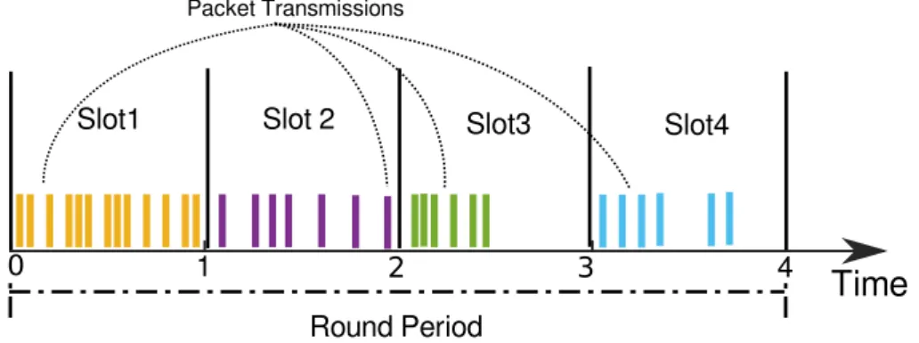
Using Time-division Multiple Access (TDMA) to guarantee timeliness has been stud-ied extensively as it is a technique that grants all nodes a periodic transmission window, called a slot, thus preventing phenomena like starvation.
Slot1 Slot 2 Slot3 Slot4 1 4 Packet Transmissions Round Period
Time
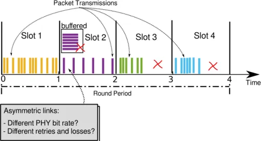
0 2 3Figure 2.3: TDMA allows each node to send packets in their own slots.
TDMA is contention-free scheme, that typically provides an exclusive (collision-free) slot to every transmitter in the network, preventing mutual interference. It grants a fixed length to the slots of all nodes (s1 = s2 = · · · = sN = T/N) as Figure 2.3 illustrates.
The round period T is constant and represents the periodicity that each node has to transmit. The set of all slots times (si) in a time period is called TDMA frame. Each
vertical colored-bar in the figure represents a packet transmission. Each color belongs to a different node. We can see that some nodes can transmit more packets than others, during the same time period.
Most wireless sensor networks using TDMA focus on guaranteeing that all nodes can communicate their own data. The fact that, in our work, middle nodes are solely relaying data, but their links can present variable throughput, makes the system prone to inefficiencies when using traditional TDMA approaches. Relays in our network only require a time slot long enough to relay incoming data while minimizing in-network queuing; hence slots should adapt to overall network throughput. Changing slot size to improve network metrics has been studied before, as in (Wandeler and Thiele, 2006), but not applied to a multi-hop aerial line network, where data is generated at one tip of the network, only, and relayed through the other nodes, over links that present variable throughput. Our work is the first to propose an adaptive overlay TDMA framework
on-2.4. MEDIUM ACCESS 23 top of CSMA/CA links in a mobile line relay network, that keeps TDMA cycles constant, but adjusts slots dynamically in a distributed fashion in order to minimize end-to-end delay.
The work in (Wang et al., 2017) also shows relationship to ours since it analyzes the behavior of multi-hop networks under TDMA versus CSMA/CA. This work addresses networks in general, focusing on a small scale case, and the authors conclude that, depending on payload size and slot length, both medium access control techniques can dominate one another in terms of worst-case network delay. However, in most such works, there is no on-line stream of sensor data; packets are sent scarcely, not generating queuing issues. When streaming data intensely, as in our case, buffer overflow becomes a strong problem and a potential cause of PDR degradation, requiring adequate traffic management to avoid stalling the network. For that reason, we intend to use TDMA implemented over CSMA/CA, which allows achieving the best of both techniques.
Therefore, to the best of our knowledge, we still miss a thorough comparison on delay, packet delivery and goodput on a multi-hop WiFi UAV network when using the native CSMA/CA vs. a TDMA overlay, specially regarding live video stream applica-tions.
It is important to clarify that there are many other RF solutions and protocols that can improve communication on a multi-hop network, such as slot re-utilization, nodes with multiple NICs on orthogonal channels, directional antennas for SNR improvement, among others. Nevertheless, those are orthogonal to the solutions we propose. Those other solutions can be applied simultaneously on top of ours to further improve network performance.
2.5 Relay Placement
Besides controlling the traffic, multi-hop wireless network improvements are generally done at management level, improving routing (IEEE802.11s, AODV, DSDV, BATMAN, and their variants) and/or coping with unreliable links using redundancy.
Routing it not really a problem in line networks. Redundancy mechanisms can be employed generically in any network, at the application level inclusively. We focus our effort on the coordination of relay placement, since it is a novel approach in UAV net-works. We found some related work in ground robotic netnet-works. For example, Lindhe and Johansson (2009) investigate how robots motion can be controlled in order to main-tain high throughput for streaming data to a base-station using a multi-hop network. They conclude that, instead of transmitting from every point directly to a gateway, it is better to concentrate transmissions in areas where/when the channel is good, slowing the robot, and then moving faster in areas with poor channel characteristics. The paper does highlight the variability and asymmetry of wireless links, which we will take into account.
Henkel and Brown (2008) analyze mobile robotic networks performance as a function of distance from a base station and required data-rate/delay requested by users. They also consider the implications of using relay nodes. When robots move far from the base, the authors propose swapping to a data mule model that leverages delay tolerant networking, giving away the live connection to the base. Although other researchers have also explored different UAV network operation modes, most tolerate breaking base connectivity, which is incompatible with the live streaming scenarios we consider under our initial vision.
Flushing et al. (2014) create a method to predict link quality based on an off-line learning phase. This predictor provides the robot network with a map of expected communication quality at any point in space. They do not measure channel performance
2.6. APPLICATIONS 25 on a real world system, and therefore our work is likely to be useful to feed real data into learning phases of tools like this.
In (Goddemeier et al., 2012), links are maintained by measuring radio-signal strength indicator (RSSI), and forcing nodes to approach it other when that value falls below a given threshold. No explicit analysis on multi-hop networks is done.
In contrast, none of the above approaches explores moving relay nodes dynamically to gain an advantage, since some applications use uncontrollable or fixed nodes or their applications do not allow it to happen. In turn, online PDR analysis on mobile networks has been addressed by several works but mostly with low throughput scenarios with static nodes (Zhao and Govindan, 2003; Jia et al., 2010). Thus, in-network buffer over-flow is not necessarily a problem, unlike our case where the video streaming needs high throughput, requiring adequate traffic management. On the other hand, the work in (Bohm et al., 2010) addresses the effect of relative speed in a vehicular network, includ-ing PDR durinclud-ing data streaminclud-ing, but it does not address multi-hop communication.
As seen in this brief survey, existing works in the literature address related but different aspects of wireless ad-hoc communication with respect to our work. Again, most of current solutions in this field are orthogonal to our proposed solution. Hence, to the best of our knowledge, we still miss a thorough packet delivery and throughput analysis of multi-hop WiFi UAV networks using relay location to improve end-to-end network performance for live video streaming.
2.6 Applications
Area monitoring problem is widely studied in the literature. There are several related projects that address sensing and coverage in robot data collection. However, there are important variations of the same main problem. Some authors consider the coverage problem with the purpose of spreading sensors as efficiently as possible to cover a given
Area of Interest (AoI), under some constraints such as communication. Others, consider the problem of monitoring a given set of points, each with a different periodicity. Nigam et al. (2012) propose that the UAVs move based on a mixed policy between closest point to visit and age of the point, i.e., how long ago it was visited. It is seen that deciding the next point to visit is of great importance, if we want to minimize the overall maximum data-age. We will focus on the problem of periodically sweeping an AoI as fast as possible, using multiple vehicles as sensors themselves, while maintaining a communication link to the GS. In (Cheng et al., 2008), the authors consider a similar problem, they propose periodic coverage to gather information from ground sensors. Their solution for multiple UAVs is to partition the route that includes all Points of Interest (PoI) into N parts and assign one part per vehicle, that will periodically visit each segment. In (Gorain and Mandal, 2013), the authors propose a solution where the space is divided into N parts and the UAVs move along the same route, where they follow each other with a certain separation. Neither of these approaches require that the UAVs are streaming data, and that they need to reduce their speed at each PoI to sense data. They also do not consider external disturbances that could eventually move the UAVs out of place.
Huang (2001) studies the shortest paths that cover a given AoI with minimum over-lap and minimum number of turns. This can be particularly interesting to consider when using airplanes. However, with a regular AoI and multirotor UAVs we can pro-vide a better (optimal in terms of distance and time) covering path. The closest work to ours that we found is that in (Franco and Buttazzo, 2015), where pictures are to be taken from an AoI. However, they do not consider periodic visits or even streaming. Their main focus is to obtain the path that minimizes energy, given a non regular AoI shape. The authors in (Yanmaz, 2012) evaluate connectivity versus area coverage in UAV networks. They propose a distributed algorithm that spreads the UAVs without breaking the network links among them, which allows streaming to be maintained. This
2.6. APPLICATIONS 27 algorithm might be suitable during the deployment of the UAVs at the AoI, but does not help in the case of periodic coverage. Finally, Tuna et al. (2012) show that UAV dy-namics are complex and important to be considered when simulating their path to their targets, if we want to obtain accurate results. For this reason, in this dissertation we will consider a more complete motion model by including non-fixed velocities, unlike the majority of coverage work.
Thus, our work contributes to the state of the art by considering the periodic coverage problem with a controlled team of multirotor UAVs that creates a streaming connection to a ground station while tolerating physical and radio interference of environmental factors.
In sensing applications, monitoring an area is usually referred as coverage. As Gorain and Mandal (2014) define within the sensor networks field, coverage is classified in two main types. The first is continuous coverage, where a set or all of the points inside a AoI are to be monitored continuously by fixed sensors nodes. The second is sweep coverage where periodic monitoring of the points inside the AoI is enough to fulfill the needs of the application. Instead of static nodes, mobile sensors are used to periodically collect data and refresh the information at the sink. Sweep coverage is now accessible due to the rapid development of mobile robotics, despite the fact that the available en-ergy in these systems is still the main limitation and source of concern (Toksoz et al., 2011; Suzuki et al., 2012; Yang et al., 2013; Franco and Buttazzo, 2015) – robot motion represents the majority of the consumed energy. Some other authors focus less on the energy consumption of the UAVs during flight, and more on the sweeping period and the minimum number of nodes needed to monitor the whole AoI (a NP-hard problem (Li et al., 2009)). Detecting unusual activities quickly enough in a wide area, such as a leak in a pipe or an intruder in a facility are good examples where the aforementioned goals are relevant.
using multiple UAV is to discretize the AoI into Points of Interest (PoI), and then create a single route that includes all of the PoI. As in (Huang, 2001), routes are typically divided into multiple parts and each part is assigned to a single vehicle. Another possibility authors in (Nigam et al., 2012) propose is that the UAVs move based on a mixed policy between closest point to visit and data-age of the point, i.e., how long ago it was visited. Alternatively, the UAVs can move along the same route and they follow each other with a certain separation.
Besides some of the assumptions usually provided in sweep coverage, works are often unrealistic. Most current approaches do not consider practical features such as adapting UAV’s velocity to stream buffered data to a sink (both buffers and wireless channel are limited), or reducing speed when reaching a PoI to sense undamaged data (eg. taking a camera snapshot without blur). We also realized that during some prelim-inary tests that flights are usually affected by external disturbances such as wind, and localization errors that can eventually modify velocity and position of the UAVs along their trajectories. Synchronizing the whole fleet is therefore another practical challenge since these conditions are often disregarded in more theoretical approaches. Correct estimation and simulation of the UAV dynamics are essential to predict the fleet perfor-mance in the real world (Tuna et al., 2012).
Most coverage scenarios regard mobile robots that collect data from a set of PoI, and upload it at a later moment to one or more sinks, by what we call data muling. This typically implies the robots move in a completely autonomous manner, disconnected from a ground station, and define their trajectories either offline, or online based on the information they receive from their sensors. However, when interactive applications are to be implemented, information must constantly be exchanged between operator and sensors. If for instance a factory or mall are being monitored and some target is detected, the operator can receive this information rapidly enough to perform remote sensor position control. An operator can opt for reassigning the AoI in order to track the
2.6. APPLICATIONS 29 target manually, or to increase the number of robots over the area to improve sensing data refresh rate. Some decisions can be autonomous, but many other are complex and still very likely dependent on human assessment of the current situation. This rationale leads us to believe that interactive monitoring systems resorting to such agile robots as multirotors and a human operator are promising and applicable in many different ways. We now see how information typically flows from an AoI to an operator.
Chapter 3
Building an Aerial Multi-hop Network
Building a UAV-based on-line stream embraces several challenges, such as establishing a reliable communication link, potentially several of them in a multi-hop fashion, to convey sensing information. In fact, it is well known that the quality of wireless com-munications degrades sharply with distance. Adding relays can improve the reliability between neighboring nodes giving them relative shorter distances. On the other hand, relays typically share the wireless channel imposing a cost on the overall throughput.These results are particularly useful for designing networks of multirotors since in these networks we can control the position of the nodes to improve the communica-tion links. This is not possible in typical mobile ad-hoc networks, such as networks of personal devices or vehicular networks. In other cases, such as networks of ground robots, position control would still be possible, but the propagation characteristics in those cases are rather different due to obstacles, multi-path, close-range and near the floor environment. In this work, we seek to provide novel insight into outdoor aerial networks of COTS multirotors, specially in characterizing and modeling their links.
This chapter we will discuss building a multi-hop line aerial network, comprised of a sensor-UAV and a variable number of relay-UAVs. We address the problem of deciding the optimal number of relays in order to optimize its performance. This work has been