UNIVERSITY OF BEIRA INTERIOR
FACULTY OF ENGINEERING Department of InformaticsConstruction of a Real
Vehicular Delay-Tolerant
Network Testbed
Maicke Cabral Gomes de Paula
Submitted to the University of Beira Interior in candidature for the Degree of Master of Science in Informatics Engineering Supervised by Prof. Dr. Joel José Puga Coelho Rodrigues
Department of Informatics University of Beira Interior
Covilhã, Portugal http://www.di.ubi.pt
Acknowledgements
First of all, I would like to thank Jehovah God for giving me health, wisdom, patience and mood to perform this work.
I thank my parents, João and Marislene, for the investments they have made throughout my life beyond the affection and love. My sister, Michele, by the incentives and my wife, Nynive, by the comprehension in the long months in which I had to devote considerable time studying and writing. I would like to thank Professor Joel José Puga Coelho Rodrigues for giving me this opportunity to join his research group, Next Generation Networks and Applications Group (NetGNA). I am most grateful for all the constants words of confidence and encouragement, for believing in the work proposal, and for supervising my Master of Science degree even though I am a foreign student.
Additionally, I would like thank to João Dias and João Isento, members of the VDTN team, for all support and help during the most difficult implementation periods.
I am most grateful to the University of Beira Interior, the Instituto de
Telecomunicações, Next Generation Networks and Applications Group
Fundação para a Ciência e a Tecnologia through the
Pest-OE/EEI/LA0008/2011 Project, and by Fiat Automobile (Product Engineering Department), Brazil, which sponsored the new hardware, laboratories and equipment. Especially I would like to thank Mauricio Vianna, my boss, for believing and investing on the proposal.
Finally, I would like to thank all persons that directly or indirectly helped me in some aspect of this project. Some colleagues of Fiat are special like Guilherme Miglio, Steven Niklaus, Alexandre Prates, and Zander Londe.
Abstract
Vehicular Delay-Tolerant Networks (VDTNs) appear as innovative network architecture, able to outline communication challenges caused by issues like variable delays, disruption and intermittent connectivity once that it utilizes the store-carry-and-forward method to allow that in-transit messages (called bundles) can be delivered to the destination by hopping over the mobile vehicles even that an end-to-end path does not exist. Since messages are stored persistently in a buffer and forward to the next hop, a new communication infrastructure is created allowing low-cost asynchronous opportunistic communication under the most critical situations like variable delays and bandwidth constraints. VDTN introduces a layered architecture, acting as an overlay network over the link layer, aggregating incoming IP packets in data bundles (large IP packets), using out-of-band signaling, based on the separation of the control plane and planes. This dissertation presents and evaluates the performance of a real VDTN testbed, demonstrating the real applicability of this new vehicular communication approach. It includes an embedded VDTN testbed created to evaluate safety systems in a real-world scenario. It was used cars with laptops to realize terminal and relay nodes. A real testbed is very important because some complex issues presented in vehicular communication systems can be treated with more realism in real-world environments than in a laboratory environment. The experiments were
manufacturing plant. Performance measurements and analysis were also conduct to verify the efficiency of the system. The results obtained show that safety applications and services can be executed with the actual proposal VDTN architecture in several environments, although notable interference as fading and characteristics of the radio channel, require the use of more modern, appropriate and robust technologies. Thus, the real deployment of VDTNs confirms that VDTNs can be seen as a very promising technology for vehicular communications.
Keywords
Vehicular Delay-Tolerant Networks; VDTN; Real Testbed, Safety Systems, Embedded VDTN, Wi-Fi, Out-of-Band Signaling, Layered Architecture.
Contents
Acknowledgements ...i Abstract ... iii Keywords ... v Contents ... vii List of Figures ... xi List of Tables ... xv Acronyms ... xvii 1. Introduction ... 11.1. Motivation for Vehicular Networks ... 1
1.2. Dissertation Objectives ... 2
1.3. Main Contributions ... 2
1.4. Dissertation Outline ... 3
2. Background ... 5
2.3. Delay-Tolerant Networks ... 9
2.3.1 DTN architecture ... 10
2.3.2 DTN routing strategies ... 11
2.4. Vehicular Delay-Tolerant Networks ... 15
2.5. Real VDTN Testbeds ... 19
2.6. Proposal of a Real VDTN Testbed ... 24
3. Construction of a Real VDTN Testbed ... 27
3.1. System Modeling ... 27
3.2. Hardware Platform ... 31
3.2.1 Embedded single board computer – PFM-945C ... 31
3.2.2 GPS device – EVK-5H ... 33
3.2.3 Wi-Fi IEEE 802.11 b/g/n – ENUWI-XAN3 ... 33
3.2.4 External omnidirectional Wi-Fi antenna ... 34
3.2.5 LCD Monitor ... 35
3.2.6 In-Vehicle Implementations – Preliminary Proposal ... 36
3.2.7 In-Vehicle Implementations – Final VDTN testbed solution ... 36
3.2.8 In-Infrastructure Implementations ... 40
3.3. Software Platform ... 43
4.1. VDTN Testbed Demonstration ... 49
4.1.1 Warning Message Service ... 50
4.1.2 Traffic Jam Information Service ... 52
4.1.3 VDTN user interfaces ... 54
4.2. Experimental Scenarios ... 56
4.2.1 Mobile-to-Terminal Node Scenario... 56
4.2.2 Mobile-to-Mobile Node Scenario ... 57
4.3. Performance Analysis... 58
4.3.1 Measurement results - Mobile-to-Terminal Node Scenario ... 59
4.3.2 Measurement results - Mobile-to-Mobile Node Scenario ... 62
5. Conclusions and Future Work ... 66
5.1. Future Works ... 68
List of Figures
Figure 2.1 - Communication channels for Car-to-X communication. ... 6 Figure 2.2 - Illustration of a vehicular network scenario. ... 7 Figure 2.3 - Illustration of the Store-carry-and-forward paradigm. ... 10 Figure 2.4 – Illustration of bundle overlay and comparison of the TCP/IP and DTN stacks. ... 11 Figure 2.5 – Illustration of the DTN bundle protocol architecture. ... 11 Figure 2.6 – Illustration of a Deep space communication in a schedule contact. ... 13 Figure 2.7 - Illustration of an opportunistic vehicular network. ... 14 Figure 2.8 -Illustration of the store-and-forward concept through VDTN networks. ... 16 Figure 2.9 - Illustration of updated traffic jams information transmission. ... 17 Figure 2.10 - VDTN layered architecture. ... 18 Figure 3.1 - State Diagram of nodes interaction. ... 28
Figure 3.4 - PFM-945C single board computer. ... 32
Figure 3.5 - M2-ATX-HV Intelligent Automotive supply. ... 32
Figure 3.6 - Ublox EVK-5H evaluation kit. ... 33
Figure 3.7 - Wi-Fi 802.11 adapter. ... 34
Figure 3.8 - Omnidirectional antenna. ... 35
Figure 3.9 – 8” Touchscreen VGA LCD monitor. ... 35
Figure 3.10 - Components of the preliminary VDTN deployment in a car: a) GPS device b) Laptop with hardware and software platform ... 36
Figure 3.11 – Final version of the VDTN deployment in a car. ... 37
Figure 3.12 - Photos of the PC-104 rack cabinet and its installation in the vehicle. ... 38
Figure 3.13 - Illustration of the external Wi-Fi omnidirectional antenna mounted on the vehicle rooftop. ... 39
Figure 3.14 - In-Vehicle implementations. ... 40
Figure 3.15 - Photos about the a) indoor and b) outdoor implementation of the terminal node. ... 41
Figure 3.16 - Photos about the relay node implementation. ... 42
Figure 3.17 - Architecture of the VDTN software platform. ... 44
Figure 3.18 - Class Diagram of the main VDTN classes. ... 45
Figure 3.19 – Positioning class diagram. ... 46
Figure 4.2 - VDTN Testbed Model for the Warning Message Service. ... 50
Figure 4.3 - Illustration of the warning message exchange between a damage car (acting as a source terminal node) and a regular mobile node. ... 51
Figure 4.4 - VDTN user interface representing the a) generation/transmission and b) receipt of the warning message... 52
Figure 4.5 - Illustration of the VDTN Traffic Jam Information Scenario. .. 53
Figure 4.6 - User graphical interface illustrating the a) generation/transmission and b) receipt of the Traffic Jam notification. . 54
Figure 4.7 - Node info tab (a); Node settings tab (b); Traffic generator tab (c); Search tab (d). ... 55
Figure 4.8 - Map view of the mobile-to-terminal node scenario. ... 57
Figure 4.9 - Map view of the mobile-to-mobile node scenario. ... 58
Figure 4.10 - Average UDP data transferred at 20 Km/h. ... 60
Figure 4.11 - Average UDP data transferred at 40 Km/h. ... 60
Figure 4.12 - Average UDP data transferred at 60 Km/h. ... 61
Figure 4.13 - Total number of data transferred and contact duration time for a vehicle with 20, 40, and 60 Km/h, sending packets of 1, 20 and 60 Kbytes. ... 61
Figure 4.14 - Average UDP data transferred at 20 Km/h. ... 63
Figure 4.15 - Average UDP data transferred at 40 Km/h. ... 63
Figure 4.17 - Total number of data transferred and contact duration time, between two vehicles with 20, 40, and 60 Km/h, sending packets of 1, 20 and 60 Kbytes ... 65
List of Tables
Table 1 - Motor Vehicle Accidents-Number and Deaths: 1990 to 2009... 1
Acronyms
ADUs : Application Data Units
AP : Access Point
API : Application Programming Interface BAD : Bundle Aggregation and De-aggregation BSC : Bundle Signaling Control
CPU : Central Processing Unit DTN : Delay Tolerant Networks EMC : Electromagnetic Compatibility GUI : Graphical User Interface HMI : Human Media Interaction
IEEE : Institute of Electrical and Electronics Engineers IP : Internet Protocol
ITS : Intelligent Transport System Kbytes : Kilo Bytes
LOS : Line-of-Sight
MANET : Mobile Ad-hoc Network Mbytes : Mega Bytes
NMEA : National Marine Electronic Association OEM : Original Equipment Manufacture SDK : Software Development Kit TCP : Transmission Control Protocol
UDP : User Datagram Protocol UML : Unified Modeling Language UN : United Nations
VANET : Vehicular Ad-hoc Network
VDTN : Vehicular Delay-Tolerant Networks V2I : Vehicle-to-Vehicle
Introduction – Chapter 1
1. Introduction
1.1. Motivation for Vehicular Networks
Vehicular networking appears as a modern trend, promoting safety improvements [1], social inclusion by providing low-cost communication for remote, rural or poor regions [2] that do not have the necessary network infrastructure and also several technological advances that enhances travelers and passengers‟ experience [3].
Safety applications represent the driving force for implementing vehicular communication. Unfortunately, thousands of death and injuries happen on the world‟s roads due distracted drivers (sending SMS messages, eating food, talking on cell phones etc.), driver behavior (e.g. running with excessive speed), road conditions, and roadway design or equipment failures (Table 1). The situation is so critical that the UN (United Nations) has set 2011-20 as the Decade of Action for Road Safety [4] recommending that users, manufacturers, and transport planners prioritize safety first. Emergence systems emerge as a technological solution to reduce accidents or anticipate the driver reaction at low cost since drivers can share experiences with each other.
Introduction
Table 1 - Motor Vehicle Accidents-Number and Deaths: 1990 to 2009. Source: U.S. National Highway Traffic Safety Administration [5].
Social development is one of the most discussed topics today. Although it is observed technological advances in first world countries the same is not true for developing countries. The technology penetration is not uniform around the world and today unfortunately there are still many nations economically backward with digital divide. In China for example, the 15 least connected provinces, with 600 million people, have only 4 million Internet users-while Shanghai and Beijing, with 27 million people, have 5 million users [6]. Vehicular communication presents as an innovative solution at low cost since in such countries, without a necessary network infrastructure, it acts as if it physically carried information over the network, proving services.
Commercial applications represent another potentially attractive area of vehicular networking. Today, cars are not only a transport mean because travelers and passengers are interesting in comfort and satisfaction while
Introduction – Dissertation Objectives
or web access to the users, and represent a cost-effective solution to automakers.
For these reasons, designing intelligent vehicular systems is a promising. Simulations [7] and real experiments [8] contribute to the modeling and analysis of several vehicular architectures. Simulations are important because permit to evaluate more realistic results, and study detailed behaviors on time-scale. However, real experiments testify the accuracy of the theoretical results and can verify if the simulation captures all the necessary fundamental characteristics.
1.2. Dissertation Objectives
The main objective of this dissertation is to design and implement a real testbed for Vehicular Delay-Tolerant Networks (VDTNs). In order to demonstrate and validate the VDTN proposal, a laboratory testbed was created [9,10]. This dissertation extends the main features of the laboratory testbed to a real deployment (an embedded VDTN testbed), created to evaluate, demonstrate and testify the research results [11-13]. Two safety services were developed with partial goals in order to implement a robust VDTN architecture and prove in practice all the main concepts of the VDTN protocol like IP over VDTN and out-of-band signaling with the separation between control and data planes.
The purpose of the preliminary version was to prove the applicability of VDTNs over different environments and evaluate the impacts of a real scenario on protocols stacks and services. The concern at this stage was simply to check the effects of applying the VDTN concept in practice. Thus, it was performed a Warning Message service to evaluate different nodes behavior (mobile, relay, and terminal nodes) in a real urban environment.
Introduction – Main Contributions
warn each other their own dangerous situation.
Once proven the applicability of the proposal, a final version was purposed as an extension of the previous. It was purposed the design and implementation of an specific embedded hardware with a suitable software for managing vehicular communications in a real environment. A Traffic Jam Information service was used to demonstrate the feasibility of this version. Basically, after obtaining traffic congestion information, cars should disseminate the alert message for the network (other cars or road side units) to allow many drivers to save time and to select an alternate route.
Finally, a real-world performance analysis was evaluated in order to verify the efficiency of the system. Using the Iperf tool, the behavior of the 802.11 b/g standard was investigated.
1.3. Main Contributions
Since the dissertation focus is to demonstrate the development and creation of a real testbed, the scientific contributions could only be achieved after the architecture implementation and the vehicular integration.
The first scientific contribution of this dissertation refers to the Warning Message scenario developed to verify the initial behavior of the VDTN nodes in a real testbed. This preliminary version was presented at IEEE Computer-Aided Modeling Analysis and Design of Communication Links and Network (CAMAD 2011), Kyoto, Japan, June 10-11, 2011, pp.16-20 [14].
Introduction – Dissertation Outline
transmission capacity among vehicles. This contribution which shows the final aspects of the real VDTN architecture, was presented at the 11th International Conference on ITS Telecommunications (ITST 2011), Saint Petersburg, Russia, August 23-25, 2011 [15].
1.4. Dissertation Outline
This dissertation is organized in 5 chapters. This chapter, the first, presents the dissertation introduction justifying the need for a real testbed in the design of vehicular networks. It is presented the main scientific contributions and the dissertation outline.
Chapter 2 introduces the background of vehicular networks describing the DTN precursor concepts and the VDTN layered architecture. It is overviewed some relevant related real testbeds, and applications or services available in the vehicular communication context.
Chapter 3 presents the requirements, specifications, design, and implementation of the proposed real VDTN architecture.
Chapter 4 focuses on the performance measurements of the vehicular communication capacity. The performance metrics and network scenarios are also described in this chapter.
Finally, chapter 5 presents the conclusions of the dissertation and suggestions for future works.
Chapter 2 - Background
2. Background
2.1. Introduction
This chapter presents the state-of-the-art and recent research projects that has been done on vehicular networking. Initially, this chapter gives an overview of vehicular networks, showing the application scenarios and benefits that have influenced investments by industry and governments. Afterwards, since DTN paradigm offered the basis of VDTNs, the concepts and the main DTN networks features are introduced. In the sequel, the VDTN layered architecture is described presenting its main characteristics. Finally, several vehicular network testbeds with advanced technologies are presented in order to testify the VDTN infrastructure proposal. The applications and services illustrate the various possible scenarios and justify the need for a real testbed to VDTNs.
2.2. Vehicular Networks
Vehicular networks are a particular type of network data transmission which vehicles act as communication infrastructure providing short-range Wi-Fi communication with each other or with the roadside infrastructure
Background – Vehicular Networks
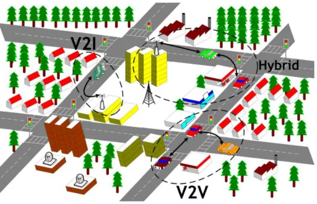
There are three main network architectures for vehicular networks: pure
vehicle-to-vehicle Ad hoc (V2V) that performs spontaneous wireless
communication without an infrastructure or pre-configuration,
Infrastructure-based (V2I – Vehicle to Infrastructure) that provides a wired
backbone for the network, once fixed nodes distributed along the roads act as access point to 802.11 infrastructure networks, and hybrid which combines the solution ad hoc with the infrastructure model. Each of these architectures has their peculiarities. The ad hoc architecture has the advantage of the fact that vehicles acting as routers can forward traffic over multi-hops in a decentralized manner, however the infrastructure architecture can be used to increase connectivity in high mobility situations and allow access to Internet. Figure 2.1 and 2.2 illustrate respectively the Car-to-X communication and the several vehicular networks architectures.
Background – Vehicular Networks
Figure 2.2 - Illustration of a vehicular network scenario.
Another aspect that should be highlighted in the development of vehicular networks refers to the fact that these specific networks have influenced large government investments in the last years. Today, in many countries there is a wide appeal for environment sustainability through cooperative
Intelligent Transport Systems (ITS) [17], economic development, and social
inclusion. It is clear that the investments in vehicular communications is advantageous in the sense that the return in terms of keep mobility, reduce road fatalities, and further improve the ecology and efficiency of road traffic is large. Investments in active safety, to prevent accidents, are a trend of the 21st century. The social context is other notable aspect, since this technology may provide low-cost communication for remote, rural or poor regions that do not have the necessary network infrastructure [18-20].
Background – Vehicular Networks
Vehicular networking also has been attracting considerable attention from the car manufacturers and automotive OEMs (original equipment manufacturers). There is a growing effort in the development of several technological solutions that enhances travelers and passenger‟s experience [21-22]. The cars are not recognized just as a mean of transport, but as an entertainment solution.
Among some main vehicular networks applications stands safety networks which are responsible for disseminate advertisements and information about road safety, speed limit, traffic jams and climate conditions [23-25], social networks [26], and interactive networks [27-28] that can offer up video streaming.
The vehicular networks have considerable challenges for large-scale application. Due the features such as high vehicle mobility, dynamic scenarios, sparsity of vehicles, short and limited contact durations, scalability in terms of number of nodes, disruption and intermittent connectivity, and strict requirements for latency, traditional routing schemes proposed for other wireless networks as mobile ad hoc (MANETs) [29] and applied to vehicle ad hoc networks (VANETs) [30] are not suitable. The different protocols [31] do not present satisfactory performance because do not assume an sporadic connection since often no end-to-end path exists between a source and its destination, and do not tolerate excessive packet drops [32]. Thus, V2V and V2I applications are not appropriated for these challenging environments. For this reason, adaptations or new protocols are required in order to permit carry data from source to destination even in situations of network partitioning or end-to-end connectivity inexistent. Recent research [33] has shown that the use of the store-carry-and-forward model proposed for DTNs allows to outline such problems since is not more necessary that the destination node be active when the source node sends the message.
Background – Delay-Tolerant Networks
2.3. Delay-Tolerant Networks
The TCP/IP based model is inefficient [34] when faced with critical situations of connectivity that causes a frequent absence of an end-to-end path between nodes. Dynamic network scenarios, long latency, high packet loss, heterogeneous transmission rates, and high bit error rates are factors that hamper the conventional routing protocols work well since they are not designed to accommodate situations of disconnection. It is not possible to determine the path or route for datagrams from source to destination without information about topology and the link costs. Due these problems, various research efforts were made to develop an appropriated network solution. The best results apply to Delay Tolerant Networks (DTNs) [35-36]. It promises to manage communication in challenged environments. Some of these environments include: wireless communications [37], communications between mobile devices with power constraints [38], underwater communications [39], battlefield communications [40], interplanetary communications [41] among others.
DTNs overcome the problems cited by using the store-and-forward method [42]. This method allows that in-transit messages (called bundles) can be delivered to the destination since each intermediary node stores than persistently and forward to the next hop. It is similar how the postal service delivers packages. Figure 2.3 illustrates the store-carry-and-forward paradigm.
Background – Vehicular Delay-Tolerant Networks
Figure 2.3 - Illustration of the Store-carry-and-forward paradigm.
2.3.1 DTN architecture
The DTN architecture implements the store-and-forward method by overlaying a new protocol layer called bundle layer [43] over the transport layer. This DTN over TCP approach allows applications to communicate with each other across heterogeneous networks providing an end-to-end data transfer. The application data units (ADUs) sent by DTN applications are transformed by the bundle layer into one or more protocol data units called bundles, which are stored-carried-and-forward by DTN nodes. The bundle term was chosen to make evidence that there is no interactivity in intermittent scenarios. Thus, all the necessary information required for a transaction is “aggregated” and sent only once to minimize the number of round-trip exchanges (e.g. optional acknowledgments, connection setup etc.). The bundle layer protocol is implemented in all DTN nodes and executes special features like dynamic routing, naming, contact scheduling, optional reliability through the custody transfer service and transmission status reports. Figure 2.4 and 2.5 presents respectively the bundle layer position in the Internet-type protocol stack and the DTN bundle protocol architecture.
Background – Delay-Tolerant Networks
Figure 2.4 – Illustration of bundle overlay and comparison of the TCP/IP and DTN stacks.
Figure 2.5 – Illustration of the DTN bundle protocol architecture.
2.3.2 DTN routing strategies
Recently, some approaches [44] have been developed to operate over defiant environments, however the routing still remains a problem because
Background – Delay-Tolerant Networks
select the best path (e.g. that minimizes the delivery ratio, the number of hops etc.) for routing, for DTN the challenge is to determine or compute routes when there is no an end-to-end path from a source to a destination. The DTN routing strategies can be divided into deterministic and stochastic cases [45] according to the knowledge available about the network topology. Once the DTN network topology is dynamic, the contact opportunities or time which links are active, may exist for only a short period during hours, days or even weeks. Thus, information about the network operation or even assumptions are useful to support multi-hop data transmission.
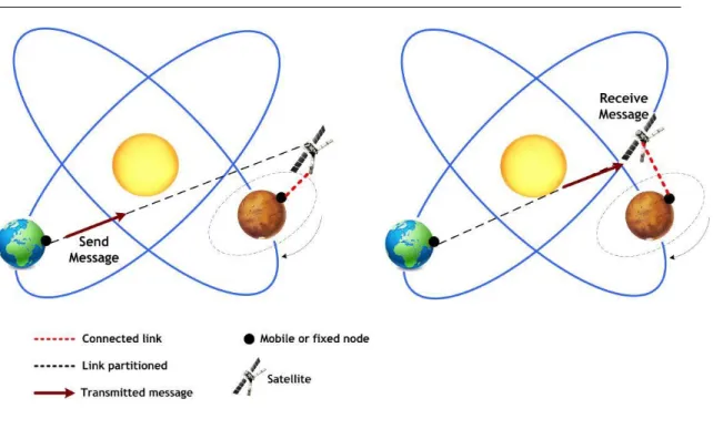
A scenario is called deterministic when the network behavior is known in advance. In this situation, connections, node information like buffer space, energy and transmission capacity, network topology, and future movements are fully known to the network nodes, allowing schedule transmissions. The accurate estimates of contact time intervals are very useful because it allows nodes to make pre-established agreements. Figure 2.6 illustrates an example of a schedule contact in a space communication. The knowledge ahead of time about topology and contacts permits accurately predict the communication between the network nodes (e.g. planets, satellites, etc.). Some papers have referenced scheduled contacts, such as described by Jain et al. [46].
Background – Delay-Tolerant Networks
Figure 2.6 – Illustration of a Deep space communication in a schedule contact.
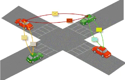
Unlike the deterministic scenario, in a stochastic scenario (or dynamic) the network behavior is not completely known. The opportunistic contacts are performed randomly at an unscheduled time. The network nodes (e.g. people, vehicles, aircraft, etc.), although are autonomous (independent mobility pattern), may communicate with any neighbor node (direct contact or within line-of-sight of nodes) in order to create communication opportunities with other nodes that are out of range. There is no guarantee that messages can reach the destination, since it is unable to calculate routes, however, is possible with some protocols increase the delivery probability. Some algorithms are based on flooding routing schemes [47] which copies of the message are replicated to all neighbor nodes. The overall goal of this epidemic technique is to maximize message delivery rate since all network nodes carry data. Other algorithms are based on estimation [48,49] which copies of the message are replicated only for nodes that have a higher probability to find the destination. There are also
Background – Delay-Tolerant Networks
probability to move towards the destination. Finally, there are algorithms based on coding [50] which only small message blocks, with redundant information, are necessary to rebuild the original message. Figure 2.7 presents an example of an opportunistic vehicular network where cars replicate messages to each other, relying on the mobility of both to disseminate data towards the destination.
Background – Delay-Tolerant Networks
2.4. Vehicular Delay-Tolerant Networks
Vehicular Delay-Tolerant Network (VDTN) is a new DTN concept where vehicles act as the communication infrastructure, furnishing low-cost asynchronous opportunistic communications, variable delays, and bandwidth limitations defining a non-TCP/IP end-to-end network. VDTN emerges as an alternative solution to outline connectivity limitations once that it utilizes the store-carry-and-forward method [51] to allow that in-transit messages (called bundles) can be delivered to the destination by hopping over the mobile vehicles, even that an end-to-end path does not exist. Since messages are stored persistently in a buffer and forward to the next hop, a new communication infrastructure is created allowing asynchronous communication under the most critical situations like variable delays and bandwidth constraints.
As mentioned in section 2.2, the traditional vehicular networks, like VANETs, do not present satisfactory performance in challenged environments because it needs of an instantaneous end-to-end path between the source and destination. However, the VDTNs were designed to tolerate the most critical scenarios which present partitioning and intermittent connectivity.
The basic entities of a VDTN, that manage the communication are terminal, mobile, and relay nodes. Terminal nodes, generally located in remote areas, are fixed devices that act as access points (APs) or servers providing to end-users real and non-real time information and services, like electronic mail (eMail), distance learning, and telemedicine. Once having direct access to the Internet, it can provide updated information about roads, weather conditions, among others. Mobile nodes (e.g. bus, cars, trains, bikes etc.), act as mobile routers and are responsible to store-carry-and-forward physically bundles between the other networks entities. A
Background – Real VDTN Testbeds
generated by sensors, although the terminal nodes is the main responsible to act as traffic sources and traffic sinks. Relay nodes are stationary nodes used to increase the bundle delivery ratio performance and the number of opportunistic contacts. Located in strategic positions (e.g. crossroads) with capability to download, store and upload data from/to mobile nodes, it can increase the probability that the bundles reach the destination. Figure 2.8 e 2.9 illustrate the store-and-forward concept and interactions between VDTN node types in a real scenario where a traffic jam message is disseminated. The network nodes store bundles persistently in a buffer or secondary memory and forward them for each other to the final destination.
Figure 2.8 -Illustration of the store-and-forward concept through VDTN networks.
Background – Vehicular Delay-Tolerant Networks
Figure 2.9 - Illustration of updated traffic jams information transmission.
In order to support communication, VDTN introduces a layered architecture (Figure 2.10), acting as an overlay network over the link layer, aggregating incoming IP packets in data bundles (large IP packets), using out-of-band signaling, based on the separation of the control plane and planes [52-54]. The new layer named Bundle Layer is responsible to outline the problems associated with intermittent connectivity since it executes a store-carry-and-forward routing allowing that data or bundles are stored in mobile nodes until the final destination is found.
Background – Real VDTN Testbeds
Figure 2.10 - VDTN layered architecture.
The VDTN bundle layer uses the out-of-band signaling with control and data planes separation. The control plane performs a type of connection
handshake (initial setup), managing the exchange of control messages
(messages that indicate if mobile nodes can exchange bundles later on) and all necessary information to establish a data connection (executed at data plane). This information includes node type, power constraints, routing, speed and course, supported physical link data rate, storage capacity, among others. This initial presentation is performed out-of-band, with a specific, low-power, long range, and low bandwidth always-on link connection, to optimize vehicle interaction that presents short contact durations. After confirming that contact is opportunistic, all efforts are made to forward bundles between nodes, so the data plane is initialized. The data plane is the responsible to exchange data bundles and uses a
Background – Vehicular Delay-Tolerant Networks
and especially power. In cars, for example, it is very important to conserve battery charge when the alternator recharging is off.
2.5. Real VDTN Testbeds
Real vehicular network testbed implementations have been developed to evaluate and demonstrate new architectures and protocols for vehicular networks. Many of these proposals were used in the VDTN context and contributed on the design and construction of the proposed real VDTN testbed. Find below the most relevant applications and services present on real vehicular testbeds.
C-VET [55] is the UCLA‟s testbed platform that integrates vehicle ad-hoc networks (VANETs) and wireless mesh network architecture with mobility support, in order to support vehicular communication and Internet access, providing a variety of applications and services. The mesh network consists on an access point installed in open spaces such traffic lights. This platform was developed to allow researchers to design, implement, and evaluate the performance of several mobility patterns, algorithms, protocols, and applications. The C-VET testbed uses approximately 50 cars, vans, and buses of the UCLA campus fleet. Each vehicle is equipped with a Cappucino PC prepared with an AR9160 (Atheros chipset) 802.11a/b/g/n, 802.11p (Daimler-Benz interface) and a Bluetooth interfaces, and sensors that monitors weather conditions. The mesh nodes feature Open WRT OS (Atheros chipset) with MadWIFI support.
UMass DieselNet testbed [56] is a platform that integrates VANET with DTN, composed of 30 buses with attached Wi-Fi nodes. The data exchange is made between the buses that are over a route and between buses and
Background – Real VDTN Testbeds
based802.11 b interface and a GPS (Global Positioning System) device. To enhance network connectivity and create additional opportunistic contacts, Throwboxes are used as relay nodes.
A testbed for development, testing, and verification of safety applications on vehicle-to-vehicle (V2V) communications systems is presented in [57]. The application was developed using off-the-shelf products (CANape from Vector and MATLAB/Simulink from MathWorks). The messages exchanged between vehicles can be recorded, analyzed and verified to provide services. Each car is equipped with a laptop that has CANape and hardware interface to vehicle bus (e.g., CAN bus).
CarTorrent [58] is an innovative new vehicular communication platform based in peer-to-peer techniques, developed to distribute safety messages and content. The architecture allows vehicles to download information from APs simply driving by and sharing information in real-time with other cars on the road. The AODV layer performs route maintenance tasks and neighbors discovering. The vehicles have a laptop with two 802.11 wireless interfaces that manage the communication V2V and V2I (vehicle to infrastructure).
The SAFESPOT [59] is an Integrated Project co-funded by the European Commission with the objective of design cooperative systems for safety road. The intelligent vehicles and roads, with appropriated sensors, can cooperate to detect in advance potentially critical situations, extending the driver‟s awareness. The cars build on the IEEE 802.11p radios. Six different Test Sites were built in six European countries to demonstrate and testing the applications.
GeoNet [60] is an EU project focused on cooperative safety systems. Based on vehicles positioning, this proposal aims to increase the road safety by implementing a network mechanism with concepts of routing and
Background – Real VDTN Testbeds
anticipated knowledge of node trajectories to enable a notification system by delivering safety messages with each other.
NoW – Network on Wheels [61] is a German Project based on C2C and C2X communication. This project utilizes WLAN IEEE 802.11 and GPS interface to allow cars to exchange information about traffic efficiency, safety and infotainment, telematics data, and car-to-home applications. The architecture is composed of vehicles and stations fixed along roads. These entities manage all network information that is exchanged.
In CarTel [62], vehicles collect and process data from a set of sensors in order to provide to the driver and other network nodes information about traffic and environmental monitoring, automotive diagnostics among others. Each car is equipped with a body control module named CarTel node which acts as the vehicle data interface. The communication is made using opportunistic wireless channel with Wi-Fi and Bluetooth interfaces. In some cases Wi-Fi access points allow nodes to access the Internet.
An Open Embedded Vehicular Android/OSGi Platform for Telematics is presented in [63]. Cars equipped with this platform may experience different functionalities of telematics applications such as web management console, navigation diagnostics and remote deployment interface. The vehicles can share infotainments information among them and perform some kind of processing, but the management system is made remotely by servers which can update application services.
CARLINK [64] is a wireless platform developed to provide efficient traffic service. Examples of service include traffic logistic, local road weather, positioning, route planner, parking places, point of interests, incident warnings, etc. The interactions between the cars are supported with Wi-Fi transceivers installed along the roads. The system utilizes CAN-bus gateway, WLAN/WIMAX and GSM/GPRS interfaces.
Background – Real VDTN Testbeds
DRIVE [65] is reconfigurable testbed developed to evaluate advanced services and communications. Based on AUTOSAR standard, its architecture is open and modular allowing multi-platform implementation. DRIVE currently supports phone-like communication (dual WI-FI/3G communications), infotainment services, web access, Google maps based GPS navigation and multimodal HMI (graphical or voice). The communication is executed in-vehicle (e.g. distributed sensors) or externally through V2V or V2I. Each vehicle is composed of a carPC hardware, wireless sensors and rooftop antennas which integrate WI-FI, UMTS and Bluetooth technologies.
A testbed to study the performance of the Vehicular Data Transfer Protocol (VDTP) in a real urban VANET is presented in [66]. A file transfer application developed in JAVA is executed between two cars, moving at different speeds (Urban Low Speed tests and Urban High Speed tests), through open roads in downtown of Malaga (Spain). Different data files of different type and length are exchanged in order to evaluate QoS of different VDTP configurations. Each car is equipped with a notebook, an 802.11 b/g device, a Wi-Fi transceiver and a 7dBi omnidirectional antenna. An experimental platform to evaluate different applications and protocols was developed in the testbed presented in [67]. In order to minimize the random aspects found in VANET scenario, in each car, experiments are run at the same time, through multiple virtual machines (running its own protocol and application) to reproduce the same environment condition. The hardware platform consists of an Intel Core 2 Duo CPU, 2GB of RAM, 120 GB hard drive, an Atheros 802.11 device, a GPS receiver and an antenna with 8dBi.
Cabernet [68] is a real-world taxi testbed developed to evaluate the data delivery to and from moving vehicles. The communication is done by Wi-Fi and Wi-Fi access points are used to provide opportunistic communication.
Background – Real VDTN Testbeds
Soekris 4801 computer, an Atheros chipset 802.11b/g, a GPS receiver, and a small 3 dBi omnidirectional antenna. To reduce connection establishment time with the APs, it was built QuickWiFi, an optimized and integrated collection of tools. This system has proven that even experiencing problems like intermittent connectivity, it is possible to transfer, when APs are available, Mbytes of data at broadband speeds.
TATPA [69] is a testbed developed by University of Bologna used to evaluate advanced transport protocols and architecture. Using a powerful and flexible emulation tool, this testbed evaluate performance of new TCP variants and new transport architecture (e.g. DTN) over heterogeneous networks that include satellite links. The architecture is composed of Linux PCs and networking tools like NistNet and Iperf. The system is accessed remotely trough a web interface that permits manage easily the testbed features.
The Shanghai urban vehicular network - SUVnet [70] is a real testbed developed to study the characteristics of a large-scale VANET. The real trace collected from the network topology of Shanghai allowed the construction of a mobility model to evaluate and design routing protocols. Using the DTN store-and-forward concept, a new epidemic protocol named DAER (distance aware epidemic routing) was proposed to improve the data delivery ratio. It was used more than 4000 taxis equipped with Wi-Fi and GPS devices.
A Smart Road testbed used to investigate IEEE 802.11 handoff in vehicular environment is described in [71]. This testbed was developed to ensure seamless connectivity in vehicle-to-infrastructure communications. In order to improve the ability to quickly switch an association to a new access point (AP), a prior knowledge about the channels of the neighbor access points is furnished for the vehicles. For quantifying Wi-Fi network
Background – Real VDTN Testbeds
architecture consists of four Wi-Fi nodes fixed on the roadway containing omnidirectional antennas of 8dBi and cars equipped with laptops running applications. The access points use a 2.4 GHz radio for connecting to wireless clients and 5 GHz radios for backhaul operation.
A testbed for verification of vehicle safety communications applications is demonstrated in [72]. This testbed was created to validate a rapid-prototyping model which is used to help to catch the bugs and errors in early stages of the development. The cars exchange safety communications messages that are recorded, analyzed, and verified through a data acquiring system. Tools like CANape from Vector, MATLAB and Simulink are used to access the vehicle bus and for manipulate the data. The results obtained are utilized for further tuning and development of the application. Each car is equipped that has CANape and hardware interface to vehicle bus (CAN of FlexRay).
All of these projects aforementioned have contributed to the conception and design of the proposed real VDTN testbed, although such proposals show VANET routing problems.
2.6. Proposal of a Real VDTN Testbed
The examples presented in the previous section prove that a real vehicular testbed deployment is an important research method, since it gives more reliable results in more realistic scenarios. In a simulation, it is possible with simplifications model and simulate a real environment to understand some specific behavior, but only a real world experiment is capable of verify with details or realism a wide spectrum of vehicular environmental parameters. However, a testbed suffers from limited scalability and
Background – Real VDTN Testbeds
In this work, the main focus will be given in the construction of a real vehicular delay-tolerant testbed. The unpredictable and unscheduled behavior of the network entities cannot be assessed only with simulations because propagation obstructions, environment interference, and random mobility may exist frequently. It is necessary to represent real situations to compare performance results from different protocols.
The main contribution of this real VDTN testbed is to provide a reliable tool to support the development and evaluation of various vehicular protocols and architectures. The proposal was implemented to demonstrate the possible external effects that may occur and affect vehicular networking. It was used an urban scenario since traffic, electromagnetic interference, weather and other factors are present at random. Some modern technologies were used like hi-gain antennas, Wi-Fi, and GPS devices.
Chapter 3 – Construction of a Real VDTN Testbed
3. Construction of a Real
VDTN Testbed
This chapter presents the requirements, specifications, design, and implementation of the proposed real VDTN architecture. The innovative advances presented go beyond the expected state-of-art vehicular communication. This section is divided in three sub-sections as follows. The first sub-section presents the VDTN high-level design. The second and third sub-section discuss the architecture design with hardware and software technologies used to create the real testbed while the fourth sub-section presents the VDTN testbed demonstration.
3.1. System Modeling
In order to facilitate the understanding and modeling of the complex VDTN system, a graphical representation of the main model components through UML language was used. The UML is very popular and permit to accelerate the debug phase. Figure 3.1 illustrates the state diagram, with responses and actions, of the interaction occurred when two network entities
Construction of a Real VDTN Testbed – System Modeling
it requests a connection for bundle transfer. Initially, control data is exchanged in order to make sure that a valid contact was achieved. If a contact was approved, it is checked if there are bundles in the buffer to exchange. If bundles are available these are delivered and the communication ends up.
Figure 3.1 - State Diagram of nodes interaction.
Construction of a Real VDTN Testbed – System Modeling
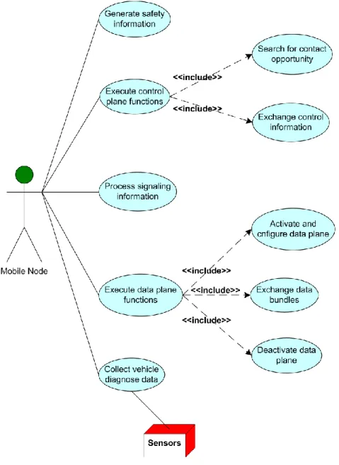
opportunities. With a Wi-Fi connection, when two nodes are within the range of each other, both exchange the control information, that is used to decide if the contact is valid and should be accepted or not. If the contact can be established, data plane is activated and configured to exchange data. Due to space constrains the use case diagrams for terminal and relay nodes cannot be displayed but they have several similarities.
Construction of a Real VDTN Testbed – System Modeling
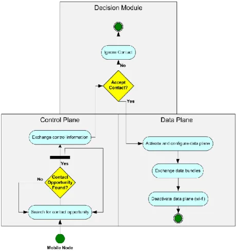
Figure 3.3 presents the activity diagram of a mobile node, presenting a flow graphic showing the activities and actions performed by the control and data planes, coordinated by the decision module. In this diagram is possible to verify the out-of-band signaling process in which control and data plane are separated. Although in this real testbed, with real cars, both the control and data plane utilizes a Wi-Fi communication, there is a well-defined separation between data transmission and control information exchanging. In critical situations which alternator is not charging properly, it is possible to conserve energy sending only specific messages with low power consumption. The main functions performed by the control plane through the control messages are resources reservation at the data plane and routing while the main functions performed by the data plane are queuing and scheduling, storage management, traffic classification etc.
Construction of a Real VDTN Testbed – Hardware Platform
3.2. Hardware Platform
This VDTN testbed was created for a real application and therefore were used embedded computers, computers, external antennas, GPS devices, and vehicles. Desktops were used for terminal and relay nodes. The next sub-sections presents with details all the components involved on the Hardware Platform and photos.
3.2.1 Embedded single board computer – PFM-945C
The cars that act as mobile nodes are equipped with a PFM-945C single board (Figure 3.4) [73] with an 8 GB Compact Flash disk. This is a PC/104 CPU module built upon the onboard Intel® AtomTM N270 1.6 GHz Processor and Intel® 945GSE + ICH7M chipset with up to 1GB of onboard DDRII 400/533 system memory. The PFM-945C offers one 10/100Base-TX Ethernet RJ-45 port as well as 4 USB2.0, 4 COM and PCI/104-Express interfaces. The PFM-945C was designed to operate in special situations requiring low power consumption and anti-vibration strategies. The storage needs are met by both SATA and CompactFlashTM interfaces.
The integration with the vehicle architecture was made powering the PFM-945C by an M2-ATX-HV Intelligent Automotive supply (140 W) 12V DC-DC ATX PC [74]. This supply is very useful because it was designed to provide power and to control the ON/OFF switch of the PFM-945C. Another important is that the M2-ATX is a 6-24V input ATX PSU capable of surviving tough engine cranks (down to 6V) as well as transient over-voltage situations. Figure 3.5 presents the M2-ATX supply.
Construction of a Real VDTN Testbed – Hardware Platform
Construction of a Real VDTN Testbed – Hardware Platform 3.2.2 GPS device – EVK-5H
For execute the most possible applications and services, the real testbed requires a GPs module that furnishes the vehicle positioning in a real time. In the testbed proposed, it was used an Ublox EVK-5H evaluation kit (Figure 3.6) [75] plugged into a USB port of the PFM-945C.
Figure 3.6 - Ublox EVK-5H evaluation kit.
This GPS device was chosen because does not require an external power supply, is easy to use and permits data transfer (NMEA string) over USB. The antenna is mounted on the vehicle panel with direct vision for the windshield.
3.2.3 Wi-Fi IEEE 802.11 b/g/n – ENUWI-XAN3
The real VDTN testbed uses an Encore‟s ENUWI-XAN3 wireless N-150 adapter (Figure 3.7) [76] compatible with IEEE 802.11 b/g/n and operation frequency of 2.4 Ghz. This device also was plugged into a USB port of the PFM-945C. It was set the 802.11 configuration parameters to use ad hoc
Construction of a Real VDTN Testbed – Hardware Platform
Figure 3.7 - Wi-Fi 802.11 adapter.
One of the advantages of this wireless network adapter is that the antenna is detachable and can be replaced for other powerful antenna.
3.2.4 External omnidirectional Wi-Fi antenna
The real testbed experiments were conduct with an omnidirectional antenna (Figure 3.8) mounted on the vehicle rooftop. Technical details of the antenna used in the measurements are reported in Table 2.
Parameter Value
Frequency range (Mhz) 2400-2500
Polarization Vertical
Gain (dBi) ≥ 9
Impedance (Ω) 50
Maximum Input Power (W) 10
VSWR ≤ 2.0
Connector RP SMA plug/TNC
Operation Temperature (ºC) -30 -- 60
Construction of a Real VDTN Testbed – Hardware Platform
Figure 3.8 - Omnidirectional antenna.
3.2.5 LCD Monitor
A Lilliput FA801-NP/C/T 8” touch screen VGA LCD monitor (Figure 3.9) [77] was fitted on the vehicle for displaying vehicle communication. It represents the user interface used to interact with the VDTN system. Once the VDTN applications are directed to safety information, the monitor operates with an interactive human machine interface able to provide accurate, dynamic, and real-time information. The touchscreen functionality permits the driver to set parameters easily.
Construction of a Real VDTN Testbed – Hardware Platform
3.2.6 In-Vehicle Implementations – Preliminary Proposal
This section presents the preliminary in-vehicle VDTN testbed implementation [14].
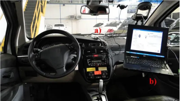
Figure 3.10 shows the first integration of the testbed in vehicles. In this first application it was used a laptop to perform the role of a central processing unit (CPU) and for presenting HMI interfaces.
Figure 3.10 - Components of the preliminary VDTN deployment in a car: a) GPS device b) Laptop with hardware and software platform
3.2.7 In-Vehicle Implementations – Final VDTN testbed solution
Construction of a Real VDTN Testbed – Hardware Platform
Figure 3.11 shows the final integration of the testbed in vehicles. In this final version it was used a touch screen monitor for the GUI and a specific hardware.
Figure 3.11 – Final version of the VDTN deployment in a car.
Figure 3.12 presents the PC-104 rack cabinet with all components: the PFM-945C single board computer and the M2-ATX-HV Intelligent Automotive supply. All the other communications interfaces (e.g. Wi-Fi devices, monitor) are connected to the ECU through USB ports. This definitive implementation acts as a central processing unit and is responsible for managing all vehicular communication. For convenience , easy maintenance and technical requirements (e.g. humidity, temperature below 60ºC etc.), the rack was installed on vehicle trunk.
Construction of a Real VDTN Testbed – Hardware Platform
1: PC 104 CPU Board 2: Compact Flash Disk 3: Voltage Supply
Figure 3.12 - Photos of the PC-104 rack cabinet and its installation in the vehicle.
Figure 3.13 illustrates the external Wi-Fi omnidirectional antenna mounted on the vehicle rooftop. Although in its basis there is a magnetic stand, it was necessary, due high speed mobility of vehicles, to improve the fixation with adhesive tapes. The cable length (approximately 4 meters) was sufficient to connect the antenna with the wireless device installed via USB on the ECU.
Construction of a Real VDTN Testbed – Hardware Platform
Figure 3.13 - Illustration of the external Wi-Fi omnidirectional antenna mounted on the vehicle rooftop.
Construction of a Real VDTN Testbed – Hardware Platform
Figure 3.14 - In-Vehicle implementations.
Construction of a Real VDTN Testbed – Hardware Platform
Figure 3.15 presents the indoor and outdoor terminal node implementation. The terminal node was installed in an internal building with Internet access. It served as an AP and was responsible to provide updated information about the safety messages which were used in the services proposed in this dissertation. An external antenna was installed in a window outside the building.
a)
b)
Figure 3.15 - Photos about the a) indoor and b) outdoor implementation of the terminal node.
Construction of a Real VDTN Testbed – Hardware Platform
Figure 3.16 presents the relay node implementation. This stationary node was placed on a road intersection in order to download, store and upload data from/to the vehicles, and increase the number of the contact opportunities or delivery ratio.
Construction of a Real VDTN Testbed – Software Platform
3.3. Software Platform
To allow the system development, integration, and management of diverse hardware components, a software platform was developed. This platform is composed by various software modules implemented in C++ / C# [78] under .Net Framework version 3.5 [79]. The development environment used was Microsoft Visual Studio 2010 IDE (Integrated Development Kit) [80]. Several characteristics like routing schemes (e.g. epidemic, spray, and wait), scheduling, and dropping policies (e.g. FIFO, random, lifetime based, etc.), associated with emulated network features (network resource constraints, applications, and services), were implemented in order to permit the network nodes to interact in different possible scenarios.
Figure 3.17 presents the structure of the software platform, which consists of components that controls the existing units in the hardware platform and abstracts communication with: the operation system to control the applications execution in the processing unit; the device drivers to communicate with the input/output devices; and the network communication system that controls and provide the communications protocols. Other important component that can be identified in the figure, is the middleware that assumes the task of abstracting the operation system to the application and the communication with other heterogeneous devices. For the application, in order to use the hardware and software components there is an Application Programming Interface (API) that connects the application with the platform. The vehicular services use the Human Media Interactions (HMI) provided by the platform.
Chapter 4 – Performance Evaluation and Measurements
Figure 3.17 - Architecture of the VDTN software platform.
Figure 3.18 details the node interactions on handling classes and gives a macro view of how the SW was designed. The macro class diagram (without class attributes and methods) illustrates classes‟ interaction and the dependence between them. ControlPlaneLink and DataPlaneLink are classes used to manage the out-of-band signaling and bundles transfer, although bundle signaling control (BSC) and bundle aggregation and de-aggregation (BAD) classes are responsible to implement the control and data planes. All actions performed by BSC and BAD are made through other special classes. Routing and Signaling classes are responsible respectively for generating and processing routing information and signaling messages.
Positioning is a special class responsible for control a GPS device and
provides location information of vehicles at every time instant (details are presented in section 3.3.1). Scheduling is responsible for applying scheduling policies to reduce transferring time and make good use of
Construction of a Real VDTN Testbed – Software Platform
discarded in case of buffer overflow. De/Aggregation is responsible for the process of aggregating incoming IP packets in data bundles and vice versa, and Classification class is accountable for traffic differentiation. VDTNHost is the main class and interacts with all other.
Figure 3.18 - Class Diagram of the main VDTN classes.
3.3.1 Positioning Class
Basically, all safety applications and services developed in vehicular communications require a geo-positioning system, usually using a GPS device. It is very important because the vehicles can know its position at
Chapter 4 – Performance Evaluation and Measurements
synchronization through the network improving the routing and consequently performance and security. Based on this, this real VDTN proposal developed a GPS positioning algorithm used for control a GPS device (Ublox) and to provide location information of cars at every time instant. This software is executed in parallel to the main software, but provides in real time information that is handled by the Positioning class. Figure 3.19 presents the Positioning class diagram representing the stored and manipulated data. It presents the main attributes and operations used to implement the positioning system.
Construction of a Real VDTN Testbed – Software Platform
Figure 3.20 illustrates the activity diagram of the positioning system. Initially the system requires a turn on command in order that the software can be synchronized with the hardware. With this step completed, the NMEA [81] cyclic reading system is activated according to the reading frequency pre-established. After this, the GPS signal class is initialized and if the GPS signal is available, the NMEA signal parameters are read. Finally, if the signal interpreted is valid and if there was an update compared with the earlier, the pipe (memory region) is loaded up with the new positioning signal that can then be used to inform localization.
Chapter 4 – Performance Evaluation and Measurements
4. Performance
Evaluation
and Measurements
In addition to demonstrating that the Warning and Traffic Jam Information services can be accomplished with the proposed VDTN testbed, a real-world performance analysis was evaluated. The objective was evaluating the transmission capacity between the vehicles using the IEEE 802.11 b/g standards. Based on this, It was executed a file transfer application where it was measured the amount of data of different sizes that can be transferred between the VDTN network nodes. In all situations, the mobile node moves at different speeds. The Iperf tool version 2.0.2 [82] was used as source traffic. Although the VDTNs do not perform the transport layer, the Iperf tool forces to set TCP or UDP as protocol. Since this time, we are concerned with evaluating only the IEEE 802.11 performance, The UDP was chosen because it has better performance [83] for vehicle applications that present lossy links. The average and the total number of data received are presented in graphics. The results also served to investigate the behavior of the 802.11 b/g standard.
VDTN Testbed Demonstration
testbed. Section 4.2 presents the scenarios used for the evaluation performance about the network transmission capacity while section 4.3 presents the performance analysis.
4.1. VDTN Testbed Demonstration
The experiments were performed on the internal streets of Brazilian Fiat Automobile manufacturing plant (Figure 4.1), at Minas Gerais, defining an urban scenario. In order to evaluate if the VDTN architecture supports the communication under a real application, it was implemented two safety services. The subsections later present the Warning Message and Traffic Jam Information services with the VDTN user graphical interface available to the driver.
Performance Evaluation and Measurements – Experimental Scenarios 4.1.1 Warning Message Service
A real urban scenario was used to perform a Warning Message service and evaluate over different nodes behavior through a real VDTN testbed . In this scenario, to prevent vehicle accidents, damaged vehicles sends a safety message to others vehicles, which make the message diffusion. The safety message contains danger information giving the GPS position of a damaged car. Figure 4.2 illustrates the VDTN testbed model for this scenario based on cars (mobile nodes), terminal, and relay nodes. A car was located in a strategic place representing a damaged vehicle and a relay node on a road intersection. Two other cars were used as mobile nodes. The damaged car was developed to automatically advertise the network that a critical unexpected situation was occurred. At a given time, when a car undergoes this vehicle, it downloads, stores the warning message generated, and forwards it to a relay node. The relay node then forwards the message for the third car completing the scenario. Figure 4.3 presents the exact time that warning message is collected.
VDTN Testbed Demonstration
Figure 4.3 - Illustration of the warning message exchange between a damage car (acting as a source terminal node) and a regular mobile node.
As may be seen in Figure 4.4, through the developed user interface, the warning message service available in the testbed is shown.
Performance Evaluation and Measurements – Experimental Scenarios
b)
Figure 4.4 - VDTN user interface representing the a) generation/transmission and b) receipt of the warning message.
4.1.2 Traffic Jam Information Service
Another real urban scenario also was used to perform a Traffic Jam Information Service. It was utilized three cars (mobile nodes), a terminal, and a relay node. A car in a traffic jam notifies this situation to another car (number 1) that store-and-forward in sequence to a relay node. This special network entity, which is responsible to increase the delivery ratio probability, forwards the safety message for the car number 2 that, finally, delivery it to the final destination (terminal node). Thus, the terminal node having Internet access, can broadcast the traffic jam message to as many users as possible. Figure 4.5 presents the opportunistic scenario used for