On an Overlaid Hybrid Wire/Wireless
Interconnection Architecture for Network-on-Chip
Ling Wang, Zhihai Guo, Peng Lv Dept. of Computer Science and Technology
Harbin Institute of Technology Harbin, China
Yingtao Jiang
Dept. of Electrical and Computer Engineering University of Nevada, Las Vegas
Las Vegas, USA
Abstract—Network-on-Chip (NoC) built upon metal low-k interconnect wires, are to meet the ever stringent performance requirements in the future technology nodes. In response to this interconnection crisis, the wireless network-on-chip (WNoC), enabled by the availability of miniaturized on-chip antennas and transceivers, is envisioned one of the most revolutionary promising approach alternatives. In this paper, we present a new WNoC architecture with a layered topology, where a metal/low-k based wired network is partitioned into several subnetworks, and these subnetworks are connected through a wireless network that is overlaid on top of them. Due to limited transmission range, the wireless nodes in the wireless network actually communicate with each other in a multiple-hop fashion. As a large volume of traffic will go through the wireless nodes, a contention avoidance routing algorithm is adopted. In addition, two virtual channels have been introduced into the wireless router design to avoid any possible deadlocks that otherwise may occur. Experiment results have shown that throughput of the proposed architecture, on average, is about 20% higher than that of the existing WNoC architectures. And delay of the proposed architecture is about 30% less than the existing WNoC architectures.
Keywords—Network-on-Chip; wireless; subnet; 2-Level Hybrid Mesh topology
I. INTRODUCTION
Network-on-Chip(NoC) has emerged as a communication backbone to enable a high degree of integration in multi-core System-on-Chips (SoCs) [1]. Conventional NoCs rely on multi-hop packet-switched communications, where a data packet needs to pass through a series of routers/switches with considerable power and latency implications. To overcome these problems, express virtual channels are introduced to various NoC architectures [2~6] that can improve NoC’s power, latency and throughput performance [2]. However, as the interconnection wires in these schemes [2-6] are still metal, delays of these metallic interconnects, governed by the physical law of showing a quadratic relationship with respect to the wire length, and are still quite long even for a modest routing distance. Therefore, on-chip interconnects carrying signals across different components will be the bottleneck to system performance and reliability, especially when CMPs scale to hundreds or thousands of cores on a chip. According to the International Technology Roadmap for Semiconductors (ITRS) [7], the wiring delay will be one of the critical issues of future designs.
The performance of NoC is expected to be significantly enhanced if wireless communication on chip technologies, such as Optical NoC, UWB and CMOS RF, are adopted [13-15]. The Optical and RF NoC are capable of inserting single-hop communication links between distant cores and thereby significantly reduce latency and power dissipation. On the other hand, the design of a wireless NoC based on CMOS ultra wideband (UWB) technology involves multi-hop communication through the on-chip short-range wireless channels. The performance of silicon integrated on-chip antennas for intra- and inter-chip communication with longer ranges have already been demonstrated in [11][12]. Antenna used in [13] can achieve a transmission range of only 1 mm but with a quite large size, the length is up to 2.98 mm. Consequently, for a NoC in a large die, say 20 mm x 20 mm, multi-hop transmissions are necessary for through-chip communications over the wireless channels. Moreover, the overheads of a wireless link may not be justifiable for 1 mm range of on-chip communication as compared to a wired channel.
In light of these technology advancements, the latest research is geared towards the mixed WNoC architectures which employ wired links between adjacent nodes and use one-hop or multi-hop wireless links between a few selected distant nodes [9][10][8]. Current WNoC architectures fall into two categories: single hop wireless NoC with long range on-chip wireless data links [9, 10], and multi-hop wireless NoC with short range on-chip wireless data links and larger number of wireless routers[8].
For one-hop wireless NoC architectures, data contention can cause severe performance problems at the wireless routers. The concept of subnet was first introduced in Small World WNoC [9], where nodes in a local subnet is wire linked and each subnet communicates with other subnets through a hub. This idea is inherited in Hybrid Mesh WNoC [10] where a traditional 2D Mesh is divided into several subnets, and each subnet has a wireless node in the center that allows this subnet to directly communicate with other subnets wirelessly. On the other hand, the multi-hop wireless NoC architectures [8], due to their higher number of wireless routers, can reduce the competition at each wireless router, but suffer from great power consumption and require large chip area.
another wired one. The wireless mesh supports multiple-hop wireless communications, so the routing paths in the wireless mesh are increased to avoid data congestion. We demonstrate the proposed architecture has low delay and high scalability.
The remainder of this paper is organized as follows. In section 2, we present the proposed WNoC architecture, followed by the description of the routing algorithm for the proposed architecture in Section 3. The wireless router design is detailed in Section 4. Section 5 presents the simulation results of the proposed architecture and its routing algorithm. Finally, we conclude the paper in Section 6.
II. WNOC ARCHITECTURE TOPOLOGY
To overcome many problems inherent in wired NoC, we propose a 2-Level WNoC architecture. Our WNoC architecture is based on a conventional wired 2-D mesh topology. Each IP here consists of a functional core, Network Interface (NI) and a router. Each router directly connects with its neighbor routers through multi-bit bidirectional links.
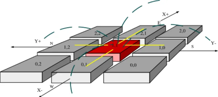
The proposed 2-Level WNoC architecture is shown in Fig. 1. In the lower wired mesh, the network is divided into a number of subnets. In each subnet, one wireless router (WR) is located in the center for inter-subnet wireless communication, and other wired routers are around the WR for intra-subnet wired communication. Then, all the WRs are connected to each outer by wireless links and constitutes the upper wireless mesh. Due to availability of multiple channels, Frequency Division Multiple Access (FDMA) method is adopted for channelization that can achieve simultaneous multiple communications between WRs.
Wired router Wireless router
Wired link Wireless link
Fig. 1. Proposed WNoC topology
This architecture has the following properties:
In this structure, wireless nodes in the network are uniformly distributed and wireless data communications can pass multiple wireless hops (routers).
In this way, the wireless links will be less likely to be congested. Each subnet of the architecture has a fixed size, and the network is scalable.
Fig.2 depicts the two-level communications of a wireless router. Through the wired links in the lower mesh, the router can connect to its four neighbors of the E, S, N, W directions. The router is also connected to distant routers wirelessly in the X+, X-, Y+, Y- directions. When source PE starts communication, packets are injected into the network and routed through either wired mesh or wireless mesh.
Fig. 2. Choosing the central node in a subnet
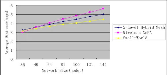
Comparisons of the proposed 2-Level WNoC with Hybrid Mesh and Small World are shown in Fig. 3 and Fig. 4. In terms of average distance of network, the 2-Level Hybrid Mesh topology is a little longer than Small-World, but shorter than Hybrid Mesh. However, when considering the number of wireless links, our proposed topology is more than the other two architectures gives more paths to route packets and balances the traffic of network. Hence, it contributes to reduce the probability of congestion in the upper wireless mesh.
III. ROUTING ALGORITHMS
The routing algorithm in the lower-layer wired mesh can be quite simple, while in the upper-layer wireless mesh, the routing algorithm needs to handle massive data volume passing through the wireless nodes.
For the proposed wireless NoC architecture, we design a routing algorithm (WFXY) with partial adaptiveness and congestion control:
Packets routed in the wired mesh follow the deterministic XY routing algorithm, which has a low algorithm complexity and guarantees the shortest path length;
In the top wireless mesh, the partially adaptive West-First routing algorithm is used to route packets to avoid data congestion.
0,0 0,1
0,2
1,2 1,1 1,0
2,0 2,1
2,2
Y+
Y-X+
X-N
W
S
Fig. 3. Average Distance of the Three Topologies
Fig. 4. Number of Wireless Links in the Three Topologies
Further, we define a threshold T for the routing distance. If a packet whose Manhattan distance between the source and the destination is greater than T, it will be classified as a long distance packet; otherwise, it is a short distance packet. The long distance packets are routed through wireless mesh, while the short distance packets can only be transferred through the wired mesh. In our experiment, the threshold T is set as 10.
A. WFXY Routing Algorithm
WFXY routing algorithm is a combination of West-First routing algorithm and XY routing. As a distributed routing algorithm, WFXY is implemented at every router, and the routing decision is made collectively by all the routers on the path from the source to the designation.
When a packet arrives at a node, WFXY algorithm will choose one from all the 8 directions (Figure 5) to switch the packet. This decision is based on the current node C, the destination node D, the packet type and available buffer sizes of its neighbor nodes.
Fig. 5. 8 possible direction of the next hop
0 1 2 3 4 5 6
36 49 64 81 100 121 144
Network Size(nodes)
Average Distance(hops)
2-Level Hybrid Mesh Wireless NePA Small-World
0 5 10 15 20 25 30
36 49 64 81 100 121 144
Network Size(nodes)
Number of Wireless Links
2-Level Hybrid Mesh Wireless NePA Small-World
Low-level mesh X+ direction
Up-level mesh X+ direction Low-level
mesh X-direction
Up-level mesh X-direction
Low-level mesh
Y-direction
Up-level mesh
Y-direction
Low-level mesh
Y+ direction Up-level
WFXY routing algorithm in wired nodes
Input: Current node C(Xc, Yc) and destination node D(Xd, Yd), the packet type;
Output: Packet routing decision;
Compute the subnet locations of nodes C and D; If packet type ==0 then //--it is a short distance packet
Route the packet to D through the wired mesh using XY strategy;
Else //--it is a long distance packet If C and D are in the same subnet then
Route the packet to D through wired mesh using XY strategy;
Else //--nodes C and D are in different subnets Route the packet to the central node of current subnet through the wired mesh using XY strategy;
WFXY routing algorithm in wireless nodes
Input: Current node C(Xc, Yc) and destination node D(Xd, Yd), the packet type, the available buffer sizes of wireless nodes in neighbour subnets;
Output: Packet routing decision;
Compute the subnet locations of nodes C and D; If packet type ==0 then //--it is a short distance packet
Route the packet to D through wired mesh using XY strategy;
Else //--it is a long distance packet If C and D are in the same subnet then
Route the packet to D through wired mesh using XY strategy;
Else //--nodes C and D are in different subnets Route the packet to the central node of destination subnet, through wireless mesh using West-First adaptive strategy;
B. WFXY Algorithm analysis
WFXY algorithm is a distributed algorithm that computing the next hop at every node takes time O(1). Hence, the overall time of determining a routing path is proportional to the length of the path. In our proposed architecture, the network diameter is smaller than 2N, so the total time complexity of WFXY is O (N). Moreover, because each node in the network keeps its location information for routing computation, the space complexity of WFXY is O (N2).
IV. WIRELESS ROUTER DESIGN
In the previous section, we classify the data packets into two types: long distance packets and short distance packets. When these two kinds of packets exist in the network at the same time, it is very likely to cause a deadlock with formed cyclic routing paths involving both wired and wireless links. To resolve this potential deadlock problem, we introduce virtual channels into the router design.
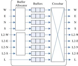
The wireless router has 9 input ports, 5 wired ports and 4 wireless ports, while the wired router has 5 input ports, all wired ports, as shown in Figure 6. Each wired port can receive both types of packets with two virtual channels, VC0 and VC1. VC0 is for the long distance packets and VC1 for the short distance packets. As the wireless port handles long distance packets only, one buffer (VC0) is sufficient. The Switch Allocator handles the requests of the virtual channels, and the switch is used alternately by these VCs. Because the long distance packets and the short distance packets are routed through different virtual channels, and no VC can dictate the switching fabric indefinitely, the possibility of having a deadlock can be eliminated.
Buffers Crossbar Buffer
Allocator W
E
N
S
L2-W
L2-E
L2-N
L2-S
L
W
E
N
S
L2-W
L2-E
L2-N
L2-S
L
Fig. 6. The design of wireless router
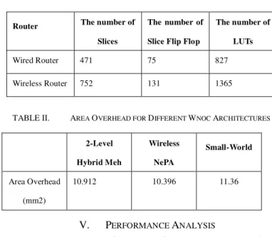
Wired and Wireless Routers are designed by Verilog HDL. The synthesis for wire router and wireless router are realized by EDA tool ISE 10.1 of Xilinx Company. The type of FPGA is XC4VSX35. The synthesis result is shown in the table 1. As the number of ports of wireless router is more than that of wired router, the hardware overhead of wireless router is 1.6 times of that of wired router.
TABLE I. SYNTHESIS RESULT OF WIRED ROUTER AND WIRELESS
ROUTER
Router The number of
Slices
The number of
Slice Flip Flop
The number of
LUTs
Wired Router 471 75 827
Wireless Router 752 131 1365
TABLE II. AREA OVERHEAD FOR DIFFERENT WNOC ARCHITECTURES
2-Level
Hybrid Meh
Wireless
NePA
Small-World
Area Overhead
(mm2)
10.912 10.396 11.36
V. PERFORMANCE ANALYSIS
To evaluate the performance of our proposed WNoC, a cycle-accurate WNoC simulator based on SystemC is used. In the experiment, we compare the performance (latency and throughput) of the proposed 2-Level Hybrid Mesh structure with that of two other WNoC architectures, Small-World and Wireless NePA. We assume that all three architectures are used to connect a system with 144 cores. Two traffic models are adopted in the experiment: (1) Uniform Random model, where every source node has equal probability to communicate with all other nodes; and (2) Hotspot model, where 8 hotspot nodes are introduced and they have to handle 15% of the total network traffic. The simulation environment is given in the table 3.
TABLE III. SIMULATION ENVIRONMENT SETTING
Parameter Setting Result
Network Size 144 nodes
Buffer Size of Virtual Channel 16 Flits
Length of Flit 32 Bits
Length of packet 5 Flits
Simulation delay 20000 clock cycles
Timer cycle 4ns
Throughput model Stochastic model、hotspot model
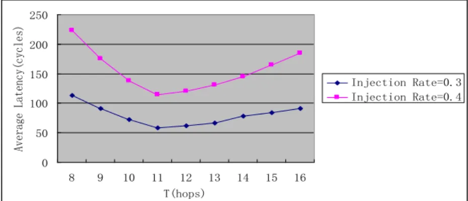
In the proposed WFXY routing algorithm, threshold T is set for dividing long distance and short distance packet according to the packet routing distance. When T is smaller, most of data packets in the network are classified as long distance packet. All of them routing at the up-level wireless Mesh network cause congestion at the up-level network. When T is larger, most of data packets in the network are classified as short distance packets. Short distance packets routing at the low-level lead to the increase of routing distance. Thus, throughput distribution at the two-level network is decided by the value of T. As threshold T has important impact on the performance of the network, the simulation experiment is used to decide the optimal value of T.
In the Figure 7, the network average delay versus T is given. Uniform stochastic model is adopted as throughput model. The injection rate is set as 0.3 and 0.4, respectively. When T is set as 8, more long distance packets routing at the up-level wireless mesh cause the congestion. Then the average delay is large. With the increase of T, the number of long distance packet is decreased. The congestion is alleviated, and then the delay is increased. Until T is set as 11, the least delay is achieved. With the increase of T, most of packets are classified as short distance packet routing at the low-level wired Mesh. Therefore the average routing distance of data packet becomes longer. And the average delay of network is increased gradually.
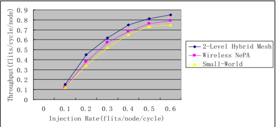
The average latency and throughput under Uniform Random pattern, measured against the traffic injection rate, are shown in Fig. 8 and Fig. 9, respectively. At low traffic load, all three architectures perform well. When the injection rate rises, the 2-Level Hybrid Mesh structure has the lowest latency and the highest throughput. It is shown in the Fig.9, when the injection rate is 0.3, average latency of the proposed architecture is lower than that of small world and wireless NePA by 50% and 27%, respectively. It is also shown in Fig.9, when the injection rate is 0.3, throughput of the proposed architecture is higher than that of small world and wireless NePA, 10% and 5%, respectively.
Under the Hotspot pattern, a lot of packets are transmitted to the 8 hotspot nodes, so the network is more likely to become congested. Fig.10 shows the average latency under the Hotspot model. When the injection rate is 0.3, average latency of the proposed architecture is less than that of small world and wireless NePA, 43% and 35%, respectively.
Fig. 7. Average Delay vs. Threshold value, T
Fig. 8. Average Latency under Uniform Random model
Fig. 9. Throughput under Uniform Random model
Fig. 10.Average Latency under Hotspot model
0 50 100 150 200 250
8 9 10 11 12 13 14 15 16
T(hops)
Average Latency(cycles)
Injection Rate=0.3 Injection Rate=0.4
0 100 200 300 400 500 600
0 0.1 0.2 0.3 0.4 0.5 0.6
Injection Rate(flits/node/cycle)
Average Latency(cycles)
2-Level Hybrid Mesh Wireless NePA Small-World
0 0.1 0.2 0.3 0.4 0.5 0.6 0.7 0.8 0.9
0 0.1 0.2 0.3 0.4 0.5 0.6 Injection Rate(flits/node/cycle)
Throughput(flits/cycle/node)
2-LevelHybrid Mesh Wireless NePA Small-World
0 100 200 300 400 500 600 700 800
0 0.1 0.2 0.3 0.4 0.5 0.6 Injection Rate(flits/node/cycle)
Average Latency(cycles)
Fig. 11.Throughput under Hotspot model
In Fig. 11, the throughput under Hotspot pattern is shown. When the traffic is ligh with an injection rate of 0.3, throughput of the proposed architecture is higher than that of small world and wireless NePA, by 11% and 6%, respectively. Similar to the result under Uniform Random model, the 2-Level Hybrid Mesh architecture still has the highest throughput, proving it performs better than the other two architectures.
VI. CONCLUSION
In this paper, we have proposed a new WNoC structure, its routing algorithm, and correspondingly, the design of the wireless router. In essence, the proposed architecture is an overlay of two networks. At the upper layer, nodes can communicate through a wireless mesh network. While at the lower level, nodes can communicate by wired links. To avoid network congestion, packets are classified as long distance packets and short distance packets, and these two packets will be routed at different virtual channels in the upper wireless network to avoid any possible deadlocks. Experiment results have shown that the proposed NoC outperforms the other two existing WNoC architectures.
REFERENCES
[1] A. Jantsch and H. Tenhunen (Eds.). Networks on Chip. Kluwer, 2003. [2] P. P. Pande, C. Grecu, M. Jones, A. Ivanov and R. Saleh, “Performance
evaluation and design trade-offs for network-on-chip interconnect architectures,” IEEE Transactions on Computers, vol. 54, no.8, pp. 1025-1040, August 2005.
[3] Q. Yang and Z. Wu, “An improved mesh topology and its routing
algorithm for NoC,” International Conference on Computational Intelligence and Software Engineering (CiSE), pp.1-4, 2010.
[4] M. Saneei, A. Afzali-Kusha and Z. Navabi, “Low-latency multi-level
mesh topology for NoCs,” International Conference on Microelectronics
(ICM'06), pp.36-39, 2006.
[5] K. Chen, C. Peng and F. Lai, “Star-type architecture with low
transmission latency for a 2D mesh NOC,” IEEE Asia Pacific
Conference on Circuits and Systems (APCCAS), pp.919-922, 2010. [6] A. Tavakkol, R. Moraveji and H. SarbaziAzad, “Mesh connected
crossbars: Anovel NoC topology with scalable communication
bandwidth,” International Symposium Parallel and Distributed
Processing with Applications (ISPA), pp 319-326, 2008.
[7] International Technology Roadmap for Semiconductors, 2007 edition [8] D. Zhao, Y. Wang, J. Li and T. Kikkawa, “Design of multi-channel
wireless NoC to improve on-chip communication capacity,” IEEE/ACM International Symposium on Networks on Chip (NoCS), pp. 177-184, 2011.
[9] S. Deb, K. Chang, A. Ganguly and P. Pande, “Comparative performance evaluation of wireless and optical NoC architectures,” IEEE International on SOC Conference (SOCC), pp.487-492, 2010.
[10] C. Wang, W. Hu and N. Bagherzadeh, “A wireless network-on-chip
design for multicore platforms,” 19th Euromicro International
Conference on Parallel, Distributed and Network-Based Processing (PDP), pp.409-416, 2011.
[11] J. Lin, H. Wu, Y. Su and L. Gao, “Communication using antennas fabricated in silicon integrated circuits, ” IEEE Journal of Solid-state Circuits, vol. 42, no. 8, pp. 1678-1687, August 2007.
[12] S. B. Lee, S. W. Tam, I. Pefkianakis and S. Lu, “A scalable micro wireless interconnect structure for CMPs,” ACM Annual International Conference on Mobile Computing and Networking (MobiCom), pp. 20-25, September, 2009.
[13] A. Shacham and K. Bagman, “Photonic network-on-chip for future generations of chip multi-processors,” IEEE Transactions on Computers, vol. 57, no. 9, pp. 1246-1260, Sept. 2008.
[14] M. F. Chang, J. Cong, A. Kaplan and M. Naik, “CMP network-on-chip overlaid with multi-band RF-interconnect,” IEEE International Symposium on High-Performance Computer Architecture (HPCA), pp. 191-202, 16-20 February, 2008.
[15] D. Zhao and Y. Wang, “SD-MAC: design and synthesis of a hardware-efficient collision-free QoS-aware MAC protocol for wireless network-on-chip,”IEEE Transactions on Computers, vol. 57, no. 9, pp. 1230-1245, September 2008.
0 0.1 0.2 0.3 0.4 0.5 0.6 0.7 0.8 0.9
0 0.1 0.2 0.3 0.4 0.5 0.6
Injection Rate(flits/node/cycle)
Throughput(flits/cycle/node)