© 2013 Science Publications
doi:10.3844/jcssp.2013.1224.1231 Published Online 9 (9) 2013 (http://www.thescipub.com/jcs.toc)
Corresponding Author: Usha Veerasamy Arivazhagu, Department of Computer Science and Engineering, Sathyabama University, Chennai, India
REPLACEMENT MECHANISM
OF CACHING TECHNIQUE FOR QUERY
ROUTING IN PEER TO PEER NETWORKS
1
Usha Veerasamy Arivazhagu and
2Subramaniam Srinivasan
1Department of Computer Science and Engineering, Sathyabama University, Chennai, India 2
Department of Computer Science and Engineering, Anna University, Regional office, Madurai, India
Received 2013-07-02; Revised 2013-07-15; Accepted 2013-07-27
ABSTRACT
In this approach we are proposing an extension to our previous work which deals with Trust Based Routing in the peer to peer network. This peer to peer network is carried out without using a caching mechanism to store the data packets while routing. To achieve this caching mechanism we have proposed methods for caching the data packets in the peers and also to replace these data packets with the new data packets in the next routing process. The method proposed to store the data packets is the Cache Mechanism approach, where this mechanism considers the throughput and the aggregated delay. To get this aggregated delay it considers the latency to return the current reply (Lc) and the latency to reply future data requests (Lf). Then
an approach has been proposed to replace this stored data packets with the new data packets for the next routing process where the old data packets are removed from the peer’s cache and the new data packets will be moved to the cache.
Keywords: Cache Mechanism, Cache Replacement, Peer to Peer Networks, Routing
1. INTRODUCTION
The network in which distributed resources are involved to perform a function in a decentralized manner is referred as P2P systems. The computation of power, data and network bandwidth are included in the resources. The distributed computing, data/content sharing, communication and collaboration or platform services are considered as functions in the network. The term decentralized is used in case of applying algorithms, data and metadata or to all of them. The scalability in terms of the node number, resource number, node autonomy, dynamicity, resource heterogeneity decentralized control and self configuration are some characteristics of P2P systems (Al King et al., 2010; Santillan et al., 2010).
The present Internet is expected to be dominated by content-oriented traffic, including but not limited to P2P traffic, which does not conform to the client-server
paradigm and generates redundant indirection overheads when users try to retrieve the desired data. Since the unstructured P2P network is less efficient due to its blind flooding search mechanism. The irregularity between the Internet design and the real usage is expected to be further increased, as the Internet is envisaged to provide the means to share and distribute multimedia business and user-centric services, with superior quality and striking flexibility from everyone to everyone. In consequence, it is necessary to redesign the internet based on a content-centric paradigm to provide data/content to the users in an efficient manner (Zahariadis et al., 2010).
If any p2p networks implement the cache mechanism it has to have a cache replacement policy else it becomes more difficulty for the peers to store all the data packets during the routing. This leads to loss of more data packets in the network and also to inefficient routing. Through this cache replacement policy it is possible to replace the cache with the most recent entries. The main drawback of this replacement policy is the risk that cache content may become obsolete. We propose trust based query routing technique for P2P Networks. Initially the node with maximum trust value is chosen as cluster head. These cluster heads are designated as trust managers. Each peer maintains a trust table which gets updated once it gets feedback from the trust manager about the resource requested peer. If the update denotes that the node is reachable and trusted, the routing is performed. Otherwise its echo time is verified again to decide the re-routing process. During peer node join or leave action, bootstrap technique is employed. Though cluster based routing reduces the overhead and delay, if the requested item is not present in the current cluster, it has to fetch the data from the other cluster (Arivazhagu and Srinivasan, 2012). If the destination node is located far away from the source cluster head, it will increase the delay. Here it explains about the secured routing among all the peers and the status of the peers. The cost of the network can be reduced by storing the data packets during the routing. Delay can be reduced by retrieving the loss of data during routing by this cache mechanism. So as an extension to the previous works, we propose a caching mechanism which can reduce the delay and overhead to great extent.
2. MATERIALS AND METHODS
Hefeeda et al. (2011) have proposed pCache method which is design and evaluation of a complete, running, proxy cache for P2P traffic. pCache transparently intercepts and serves traffic from different P2P systems. A new storage system is proposed and implemented in pCache. This storage system is optimized for storing P2P traffic and it is shown to outperform other storage systems. In addition, a new algorithm to infer the information required to store and serve P2P traffic by the cache is proposed. The advantage of this approach is that this method saves the bandwidth usage and also reduces the load on the backbone links.
Zhao et al. (2010) have proposed a novel asymmetric cooperative cache approach, where the data requests are transmitted to the cache layer on every node, but the data
replies are only transmitted to the cache layer at the intermediate nodes that need to cache the data. This solution not only reduces the overhead of copying data between the user space and the kernel space, it also allows data pipelines to reduce the end-to-end delay. They have also studied the effects of different MAC layers, such as 802.11-based ad hoc networks and multi-interface-multichannel-based mesh networks, on the performance of cooperative cache. The advantage of this approach is that it can significantly reduce the data access delay compared to the symmetric approach due to data pipelines.
Filali and Huet (2010) have proposed two schemes which can be used to improve the search performance in unstructured peer-to-peer networks. The first one is a simple caching mechanism based on resource descriptions. Peers that offer resources send periodic advertisement messages. These messages are stored into a cache and are used for routing requests. The second scheme is a dynamic Time-To-Live (TTL) enabling messages to break their horizon. Instead of decreasing the query TTL by 1 at each hop, it is decreased by a value v such as 0 <v<1. The main aim of this approach is it achieves a high success rate while incurring low search traffic.
Akon et al. (2010) have proposed Systematic P2P Aided Cache Enhancement or SPACE, a new collaboration scheme among clients in a computer cluster of a high performance computing facility to share their caches with each other. The collaboration is achieved in a distributed manner and is designed based on Peer-to-Peer computing model. The objective is to provide a decentralized solution and a near optimal performance with reasonably low overhead. The advantage of this approach is that the SPACE evenly distributes workloads among participators and entirely eliminates any requirement of a central cache manager.
2.1. The Cache Mechanism Approach
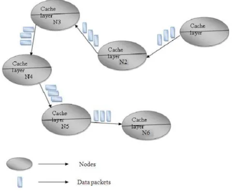
In this cache mechanism, in the first phase after a request message is generated and it is passed down to the cache layer of the node. To forward this request message to the next hop, the cache layer wraps the original request message with next hop address to reach the destination. Here, we consider that the cache layer which caches the incoming data packets of the node can access the routing table and find the next hop to reach the destination node. This way the packet is received and processed hop by hop on the path from the requester to the destination node. The destination node needs to determine the benefit of caching data packets on an intermediate node and decide whether to cache the data or no. After an intermediate node (Ni) caches data
packets forwarding the requests to the destination node, saving the communication overhead between Ni and the
data center. In the Fig. 1 it actually explain the purpose of the cache layer in nodes. Here the N1 node which is the source node sends the data packets to the destination node N6. These data packets sent by the source node reaches the destination node through the intermediate nodes between them. When these data packets are transmitted from the source node every intermediate node caches the data packets in them. After caching these data packets the intermediate node forwards those data packets to the next hop in the network. This way the data packets are stored in all the intermediate nodes till the data packets reaches the destination node. So that if any data packets are lost during the transmission the data packets can be requested from the intermediate node instead requesting the source node again.
2.2. Frequency at a Node
Node’s frequency to access max data packets per unit time, but excluding the requests forwarded from other nodes on the forwarding path. To compute this Frequency of a node, a node first count all the requests it receives for the given data packet and also the requests generated by itself then divide by the amount of time since the node starts to participate caching. This way it computes the total data request frequency (ri). The node
can attach the value of ri to the forwarding request. When
the destination node receives the value of ri for each
node along the path, it can compute Nf as Equation (1):
if1 i≤ ≤ −r 1
i i+1 f
n
r r
N ifi = n
r − =
(1)
2.3. Node Delay
The delay to forward a data item with size S from the cache layer of Ni to the cache layer of Nj, without handing
the data up to the cache layer of any intermediate nodes. ND i,j[S] is hard to measure because it is affected by many
factors, such as transmission interference, channel diversities, node mobility, Equation (2):
j 1
ij
k i
ij k,k +1
S 1 * M
M M
ND [S] =
Tp Tp − = − +
∑
(2) Where:ND i,j[S] = The node’s delay from one node to other
with S as the data size
Tpk,k+1 = The link throughput between the
neighboring nodes
M = The size of MTU (Maximum Transmission Unit) which as to be set
Tpi,j = The throughput between two caching nodes
In a cache placement mechanism the total delay (D) is aggregated. To get this aggregated delay we also consider the latency to return the current reply (Lc) and the latency
to reply future data requests (Lf) Equation (3):
( )
( )
i i+1
m
m m-1
C S 0,C1 S
i =1 i =1
S S
C ,C
C ,n
L = P(D ) + ND (D ) + ND
D ND D
+ + +
∑
∑
(3)
Lc = Refers to the latency to return the current reply
ci = Refers to the subscript of the node Nci on the
forwarding path, which implies that node Nci is
ci hops away from the destination.
DS = Refers to the data size
P(DS) = Refers data processing delay
At m nodes the data are reassembled and the forwarding path is cut into m+1 piece, respectively. Where, fj is the excluded data access frequency at node j;
RS is the size of the request message for the data request
DS is the size of the data, respectively. Finally the Cache
Placement (CP) set is optimal if it can minimize the Equation (4):
i+1
f i 0, j S 0, j S
j=1
m -1
j S S
i =1 i =1 n 1
j S S
C11
C 1
C , ji C , ji
Cm, j Cm, j
j Cm
L = f (ND (R ) + ND (D )) t
f (ND (R ) ND (D )) t
f (ND (R ) ND (D ) t
Fig. 1. Cache mechanism approach weighted aggregate delay D, which is given by:
D = LC + Lf
2.4. Throughput
When the links lj uses the channel different from the
(lj-1 …… lj-h) within its interference range h hops
Equation (5):
i, j+1 i, j j, j+1
Tp = min (Tp ,Tp ) (5)
When both the links lj and (lj-1 …… lj-h) uses the
same channel for the transmission of the data packets in the network then Equation (6):
i, j+1
i, j j, j+1
1
Tp =
1 1
+
Tp Tp
(6)
2.5. Caching Mechanism Algorithm
1. for all nodes Ni to Ni-1
2. Check the trust based routing is satisfied 3. End if
4. Checks the Throughput with the Link Throughput Tp[i,i+1] = LT[i]
5. Then check for
Throughput of the links between the nodes, Tpi, j
Delay of forwarding data packets, NDd[i, j]
6. When the delay D tends to NDd[0,n]
7. When cache placement (CP) set becomes null 8. Caching nodes (Cn) for the destination becomes 0
9. D tends to D + f[i] (Dd[0,i] + Rd [0,i]) t
10. for all k=0 to n-2 do
11. LC ← P(DS) + NDd[pos, k+1] + NDd[k+1, n] -
NDd[pos, n]
12. Lf← 0
13. for all i=k+1 to n-1 do
14. Lf← Lf + (NDd[pos, i] + Rd[pos, i] - NDd[k+1, i]
- Rd[k+1, i]) f[i] t
15. end for 16. D = LC + Lf
17. D`← D + LC - Lf
18. if D` < D 19. D ← D`
20. CP ← CP U Nk+1
In the above algorithm, initially the routing is formed through the trust based routing which is the previous work. Once the trust based routing is satisfied, the search for the cache will takes place in the network. During this process the source peer checks the Throughput (TP) of the node and its neighbor node with the Link Throughput (LT) of the node. Then it checks when the total Delay (D) tends to the Node Delay (ND) i.e. the delay occurred when the Cache Placement (CP) set becomes null to the destination i.e. When k = 0, no cache node is found between the destination and the source. This total delay D is the sum of latency to return the current reply (Lc)
and the latency to reply future data requests (Lf). From
this total delay the optimal Delay (D`) is calculated. For this optimal delay also considers the variations in the Lc
and Lf i.e., LC and Lf. If this optimal delay is less than
the total delay then the total delay tends to optimal delay. Then finally the optimal Cache Placement (CP) set is found from the total caching Nodes (Nk).
2.6. Cache Replacement Policy
The cache replacement policy in the network defines a strategy for replacement of items when supplementary space is needed in the cache. The strategy is used to assign values to the items in the cache; the items with the lowest value are then replaced first. Since these cached resources could become out-of-date under resource dynamicity because the longer a resource is cached, the staler it becomes. So whenever a data packet is received, the peer extracts the details of different resources and peer get updated whenever an entry is made by the data packets into the cache layer.
After the entry the peer first checks if there is a related cache entry. If any entry is found then the peer updates this entry. Then finally the data packet will overwrite previous cache entries in the peer. Some of the most known cache replacement policies are First in First Out (FIFO), Random, Least Recently Used (LRU) and Least Frequently Used (LFU). An important asset is that the cache size does not depend on the number of peers in the network. But rather, the cache size depends on the number of different resource classes due to resource aggregation policy (Filali and Huet, 2010; Akon et al., 2010).
2.7. Systematic P2P Aided Cache Enhancement
(SPACE)
In the peer to peer network a peer maintains a set which is known as Local Cache Information (LCI) which refers to the local cache. This set of LCI includes an entry for each of the locally cached disk blocks. An entry x of LCI (denoted as LCI(x)) consists of the tuple (ax,
clkx, obx, ptrx). Here, ax is the address that the first block
LCI(x) is holding. The clkx maintains the clock tick since
the last reference of the cache block. The obx factor is a
simple flag and indicates the novelty of a cache block. When a cache block is retrieved from the destination, it is marked as original and replicas of an original cache block are designated as non-original. The last tuple element ptrx holds the reference to the local cache
memory where the actual disk data is physically.
2.8. Cache Replacement Policy Algorithm
1. Search for a peer p € LCI, such that clkp < clkmin
2. If the peer p is not null, then
3. search for peer p € LCI such that clkp≤ clkn and obp≠
originality where n €LCI and p≠n 4. Mark that peer p for replacement 5. Remove data from peer p cache
6. Move the data packets to the peer p cache 7. Return peer p
8. End
Initially in the cache replacement policy the source peer searches for a neighbor peer p to check whether the peer’s cache. This checking is done in order to know that the cache is already filled with the data or the cache is free. If the cache is free the data packets are stored in it directly. If the peer’s cache is not free the source peer checks the clkp which maintains the clock tick since the
last reference of the cache block and compares this last reference with the new reference which has to be stored i.e. clkn where the old data of the cache should not be
same with new data packets to be added. Also the source peer checks for the status of the originality of the block. Then that peer will be marked for the replacement and the old data packets will be removed and the new data packets will be moved to that peer’s cache.
3. RESULTS AND DISCUSSION
3.1. Simulation Results
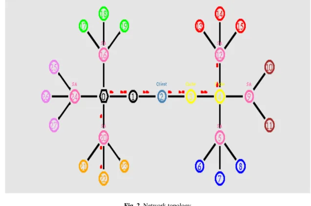
Fig. 2. Network topology
Fig. 3. Rate Vs received bandwidth
Fig. 4. Rate Vs delay
3.2. Based on Rate
In our first experiment we vary the transmission rate as 250,500,750 and 1000Kb.
From Fig. 3, we can see that the Received bandwidth of our proposed TBICSQ is higher than the existing SPACE technique. From Fig. 4, we can see that the delay of our proposed TBICSQ is less than the existing SPACE technique. From Fig. 5, we can see that the throughput of our proposed TBICSQ is higher than the existing SPACE technique. From Fig. 6, we can see that the packet drop of our proposed TBICSQ is less than the existing SPACE technique.
3.3. Based on Cache Size
In our second experiment we vary the cache size as 100,200,300,400 and 500.
Fig. 5. Rate Vs throughput
Fig. 6. Rate Vs drop
Fig. 7. Cache Size Vs received bandwidth
Fig. 8. Cache size Vs delay
Fig. 9. Cache size Vs drop
Fig. 10. Cache size Vs throughput
4. CONCLUSION
In this approach we are proposing an extension to our previous work which deals with Trust Based Routing in the pee r to peer network. This peer to peer network is carried out without using a caching mechanism to store the data packets while routing. To achieve this caching mechanism we have proposed methods for caching the data packets in the peers and also to replace these data packets with the new data packets in the next routing process. The method to store the data packets is the Cache Mechanism, where this mechanism considers the throughput and the aggregated delay. To get this aggregated delay it considers the latency to return the current reply (Lc) and the latency to reply future data
requests (Lf). Then to replace this stored data packets
delay is decreased in the network. By the simulation results it shows that the proposed technique reduces the delay, increased in throughput and minimization of Packet drop. When compared to the existing technique .In future, this work is extended to focus with specific replacement policy algorithm and security issues with simulation results.
5. REFERENCES
Akon, M., T. Islam, X. Shen and A. Singh, 2010. SPACE: A lightweight collaborative caching for clusters. Peer-to-Peer Netw. Appli., 3: 83-99. DOI: 10.1007/s12083-009-0047-5
Al King, R., A. Hameurlain and F. Morvan, 2010. Query routing and processing in peer-to-peer data sharing systems. Int. J. Database Manage. Syst. DOI: 10.5121/ijdms.2010.2208
Arivazhagu, U.V. and S. Srinivasan, 2012. Cluster based intelligent semantic query routing technique in peer to peer network. Eur. J. Scientif. Res.
Brunkhorst, I. and H. Dhraief, 2007. Semantic caching in schema-based p2p-networks. Proceedings of the International Conference on Databases, Information Systems and Peer-to-Peer Computing, Aug. 28-29, Springer Berlin Heidelberg, Trondheim, Norway, pp: 179-186. DOI: 10.1007/978-3-540-71661-7_17
Filali, I. and F. Huet, 2010. Dynamic TTL-based search in unstructured peer-to-peer networks. Proceedings of the 10th IEEE/ACM International Conference on Cluster, Cloud and Grid Computing, May 17-20, IEEE Xplore Press,Melbourne, Australia, pp: 438-447. DOI: 10.1109/CCGRID.2010.66
Hefeeda, M., C.H. Hsu and K. Mokhtarian, 2011. Design and evaluation of a proxy cache for peer-to-peer traffic. IEEE Trans. Comput., 60: 964-977. DOI: 10.1109/TC.2011.57
Santillan, C.G., L.C. Reyes, E.M. Conde, G.C. Valdez and S.E. Schaeffer, 2010. A self-adaptive ant colony system for semantic query routing problem in P2P networks. Comput. Sist., 13: 433-448.
Zahariadis, T., F. Junqueira, L. Celetto, E. Quacchio and S. Niccolini et al., 2010. Content aware searching, caching and streaming. Proceedings of the 2nd International Conference on Telecommunications and Multimedia, Jul. 14-16, Chania, Crete, Greece, pp: 263-270.