An Embedded Converter from RS232 to Universal Serial Bus
zyxwvutsrqponmlkjihgfedcbaZYXWVUTSRQPONMLKJIHGFEDCBA
Ana Luiza de Almeida Pereira Zuquim
Claudionor
JosC
Nunes Coelho Jr.
Antanio Ot6vio Fernandes
Marcos
PCgo
de Oliveira
AndrCa Iabrudi Tavares
zyxwvutsrqponmlkjihgfedcbaZYXWVUTSRQPONMLKJIHGFEDCBA
Departamento de CiZncia da Computago
Universidade Federal de Minas Gerais
{ana, coelho, otavio, marcospo, iabrudi} @dcc.ufmg.
br
zyxwvutsrqponmlkjihgfedcbaZYXWVUTSRQPONMLKJIHGFEDCBA
Abstract
Universal Serial Bus (USB) is a new personal computer interconnection protocol, developed to make the connection of peripheral devices to a computer easier and more efficient. It reduces the cost for the end- user, improves communication speed and supports simultaneous attachment of multiple devices (up to 127). RS232, in another hand, was designed to single device connection, but is one of the most used communication protocols.
An embedded converter from RS232 to USB is very interesting, since it would allow serial-based devices to
experience USB advantages without major changes. This work describes the specification and development of such converter and it is also a useful guide for implementing other USB devices. The converter specification was based
on
Engetron UPS’ serial communication requirements and its implementation uses a Cypress microcontroller with USB support.1.
Introduction
This paper describes the specification and implementation of a converter from RS232 to USB (Universal Serial Bus). This converter is responsible for receiving data from a peripheral device’s serial interface and sending it to a computer’s USB interface. In the same way, it must be able to send data from the PC’s USB interface to the device.
The problems faced with the old standards stimulated the development of a new communication protocol, which should be easier to use, faster, and more efficient. USB is a new personal computer interconnection standard developed by industry and telecommunication leaders, which implements the Plug and Play technology. It allows multiple devices connection (up to 127) and solves problems like resource conflicts, IRQs, and DMAs [3],
easing the devices attachment to PCs. USB is a low cost
solution and supports transfer rates up to 12Mbs, comprehending the low-speed and mid-speed data ranges.
The use of a converter from a serial interface to USB would free a serial communication port to other applications, allowing a device that uses a serial interface to communicate using an USB interface. This way, we are not limited to the availability of a serial port and we can experience the USB advantages. Using a converter allows
us to have the device unchanged, making the converter responsible for treating the differences between the protocols.
This work was based on Engetron UPS, which can be managed by exchanging data with a PC across a serial interface. Most of the times, this communication is not done constantly, since it is necessary to have a serial port available just for it.
This paper presents the converter implementation, focusing on the development process, which comprehends the device itself and the PC-side software that will communicate with it. This methodology can be extended
to other devices.
We first present some important USB standard concepts. Then, we define the system specification, divided on host and device requirements. After, we describe the hardware (microcontroller) features and software design and implementation. Finally, we discuss about achieved results and future work.
2.
USB
-
zyxwvutsrqponmlkjihgfedcbaZYXWVUTSRQPONMLKJIHGFEDCBA
Global Overview
The USB specification describes bus attributes, protocol definition, programming interface and other features required to design and build systems and peripherals compliant with the USB standard. We briefly explain features used in our project, a deeper approach can be found in [ 1 , 31.
USB works as a Master/Slave bus, where the USB Host is the Master and the devices are the Slaves. The only system resources required by a USB system are the memory locations used by USB system software and the
memory and/or
zyxwvutsrqponmlkjihgfedcbaZYXWVUTSRQPONMLKJIHGFEDCBA
YO
address space and IRQ line used by the USB host controller.USB devices can be functional (displays, mice, etc) or hubs, used to connect other devices in the bus. They can be implemented as low or high-speed devices. Low-speed devices are limited to a maximum 1,5 Mb/s rate. Each
device has a number of individual registers
zyxwvutsrqponmlkjihgfedcbaZYXWVUTSRQPONMLKJIHGFEDCBA
- known aszyxwvutsrqponmlkjihgfedcbaZYXWVUTSRQPONMLKJIHGFEDCBA
Endpoints
-
which are indirectly accessed by the device drivers for data exchange. Each endpoint supports particular transfer characteristics and has a unique address and direction. A special case is Endpoint 0, which is used for control operations and can do hi-directional transfers. It must be present in all devices. According to the device’s characteristics, other types of endpoints can be defined.USB Host verifies the attachment and detachment of new devices, initiating the enumeration process and managing all the following transactions. It is responsible to install device driver (based on information provided by device descriptors), to automatically reconfigure the system (hot attachment) and to collect statistics and status of each device.
Device’s descriptors specify USB devices attributes and characteristics and describe device communication requeriments (Endpoint Descriptors). The USB host uses this information to configure the device, to find its driver, and to access it.
Devices with similar functions are grouped into classes
[ 1, 21 in order to share common features and even use the same device drivers. Each class can define their own descriptors (class-specific descriptors), as for example, HID (Human Interface Device) Class Descriptors and
Report Descriptors.
The
HID
class consistsof
devices used by people to control computer systems. It defines a structure that describes a HID device, with specific communication requirements. According to the converter characteristics, it can be implemented as a HID device, using already developed HID drivers. A HID device’s descriptors must support an Interrupt IN endpoint and the firmware mustalso contain a report descriptor that defines the format for transmitted and received device data.
2.1.
Requests
The USB protocol is based on requests sent by the host and processed by the USB devices. These requests can be directed to a device or a specific endpoint in it.
Standard requests must be implemented by all devices and are used for configuring a device and controlling the state of its USB interface, among other features.
Two HID-specific requests must be supported by the converter: SetReport and GetReport. These requests enable the device to receive and send generic device information to the host. SetReport request is the only way
the host can send data to a HID device, once it does not have an Interrupt OUT endpoint.
2.2.
Communication Flow
USB is a shared bus and many devices might use it at the same time. The devices share the bandwidth using a protocol based on tokens and commanded by the host. USB communication is based on transferring data at regular intervals called frames. A frame is composed by one or more transactions that must be executed in a 1 ms time.
USB data transfers are typically originated by a USB Device Driver when it needs to communicate with its device. It supplies a memory buffer used to store the data in transfers to or from the USB device.
The USB Driver provides the interface between USB Device Driver and USB Host Controller, translating transfer requests into USB transactions, consistent with the bandwidth requirements and protocol structure. Some of these transfers consist of a large block of data, which need to be splitted into several transactions.
The Host Controller generates the transaction based on
the Transfer Descriptor, which describes the frame sharing among the several devices requests.
When a transaction is sent to the bus, all devices see it. Each transaction begins with a packet that determines its type and the endpoint address. The USB driver controls this addressing scheme.
Inside the device, the USB Device Layer comprehends the actual USB communication mechanism and transfer characteristics. USB Logical Device implements a
collection of endpoints that comprise a given functional interface, which can be manipulated by its respective
USB
client.
2.3.
Transfer Types
The USB specification defines four transfer types: Control, Interrupt, Isochronous and Bulk.
Control transfers send requests and data relating to the device’s abilities and configuration. They can also be used
to transfer blocks of information for any other purpose. Control transfers consist of a Setup stage, followed by a Data stage, which is composed of one or more Data transactions, and a Status stage. All data transactions in a
Data Stage must be in the same direction (In or Out). Interrupt transfers are typically used for devices that need to transfer data at regular period of time, and consequently must be polled periodically. The polling interval is defined in the Endpoint Descriptor. The data payload for this kind of transfer for low-speed devices is 8
bytes. Error correction is done in this kind of transfer. Two other transfer types are Isochronous and
Bulk,
rate or for large blocks of data tranfers. They are not used
in this work.
zyxwvutsrqponmlkjihgfedcbaZYXWVUTSRQPONMLKJIHGFEDCBA
3.
System Specification
To develop a USB peripheral we need all the
following:
.
zyxwvutsrqponmlkjihgfedcbaZYXWVUTSRQPONMLKJIHGFEDCBA
A host that supports USB.
.
Driver software on the host to communicate with the peripheral..
An application executing in the host that communicates with the peripheral device.
.
A controller chip with a USB interface.
.
Code implementation on the USB controller to carry out the USB communication..
Code implementation on the USB controller to carry out the peripheral functions.
3.1.
Host requirements
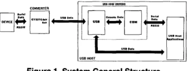
The choice of the Operating System used by the host was done in 1999, based on the USB support it provides. It should provide the entire drivers infrastructure and support the protocol characteristics, as for example, Plug and Play. At that time, our options were limited to W i n d o w s 9 P OSR2 and W i n d 0 w s 9 8 ~ ~ , both from Microsoft. We chose the second one, once the USB support in the first one was still restricted to some classes and applications.
The host must be able to receive USB data using its device drivers and make them available to the applications that have done the request. It is essential that we have a driver in the host to process USB transfers, recognizing the device, receiving and sending data to a USB device. It is desirable to have a device driver to virtualize a serial port, simulating a real COM port. This driver should be able to receive and send USB data and expose them as if they were being received and sent to a real COM port. This would allow an application to remain unchanged. This is desirable, but not essential, once we
can modify the application to deal with USB data.
zyxwvutsrqponmlkjihgfedcbaZYXWVUTSRQPONMLKJIHGFEDCBA
LLI. "OS, P m v u
I
I
I
"I. D I .zyxwvutsrqponmlkjihgfedcbaZYXWVUTSRQPONMLKJIHGFEDCBA
USE HOST
Figure 1. System General Structure
From the applications point of view, they must be able to receive and send data, which can be done using a
virtualized serial port or even modifying it to deal with USB data. Microsoft provides a device driver called USB
POS driver, which was developed to allow applications to access USB devices as if they were connected to a standard serial port (COM). The system general structure can be viewed on Figure 1.
3.2. Device requirements
Some communication requirements, such as transmission speed, frequency and amount of data to be transferred, were essential in the process of defining the microcontroller to be used.
Considering the communication speeds available for USB devices, it was clear that the converter could be implemented as a low speed device, where the communication speed varies from 10 to 100Kb/s. Considering the amount of data transferred and the transmission frequency, the converter was defined to use Interrupt transfers, a transfer type where considerable amounts of data must be transferred in pre-defined amounts of time.
The host is responsible for verifying if the device needs to transmit data from time to time. Interrupt transfers can be done in both directions, but not at the same time. For the converter, they could be used to send and receive data from the PC. The Operating System provides HID drivers that allow us to use this transfer type. The maximum packet size for one transaction is 8
bytes for low speed devices. If we are sending larger amounts of data, they need to be splitted into many transactions, once USB is a shared bus.
Another feature defined for the converter was the number of endpoints needed. As explained before, endpoints are buffers in a microcontroller used to store sent and received data in the USB communication process. Two endpoints were defined for the converter, where the first one is Endpoint 0, used for control operations and the second one is an Interrupt IN Endpoint, defined for sending data to the host.
This way, a converter from a serial interface to USB can be implemented as a HID device with the features mentioned above.
Once we have these requirements defined, we did a detailed study about the microcontrollers available, taking in count some parameters such as memory space, price and development kits. Microcontrollers from companies like Motorola, AMD and others were also analised, and we chose a Cypress microcontroller family, which presented good examples as application notes and was widely used by other developers.
4.
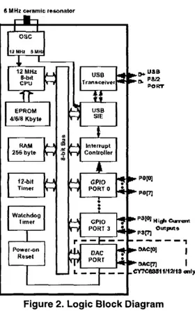
Hardware Description
speed applications with high I/O requirements. The microcontrollers have 256 bytes of RAM and from 4 to 8
Kbytes of EPROM, according to the microcontroller
model. The family is USB specification
zyxwvutsrqponmlkjihgfedcbaZYXWVUTSRQPONMLKJIHGFEDCBA
[ 11 compliant andsupports one address and three data endpoints
zyxwvutsrqponmlkjihgfedcbaZYXWVUTSRQPONMLKJIHGFEDCBA
[5].The choice of a microcontroller with three endpoints was done in order to allow us to have, beyond the Interrupt IN, an Interrupt OUT endpoint for receiving data from the host (OUT). This would allow us to use the Microsoft POS driver, which is a device driver that virtualizes a COM port. It's definition requires we have an odd endpoint number besides Endpoint 0. This configuration could not be implemented at the time the project was being developed once the Operating System did not offer support for Interrupt OUT endpoints, which were defined in a later version of the specification.
The instruction set has been optimized specifically for USB operations, since the microcontrollers have an USB transceiver and an USB Serial Interface Engine (SIE) (see Figure 2 taken from [5]), although, the microcontrollers can be used for a variety of non-USB embedded applications. The SIE allows the microcontroller to communicate with the USB host. It simplifies the interface between the microcontroller and USB by incorporating hardware that handles some USB bus
activity independently of the microcontroller.
zyxwvutsrqponmlkjihgfedcbaZYXWVUTSRQPONMLKJIHGFEDCBA
I I
zyxwvutsrqponmlkjihgfedcbaZYXWVUTSRQPONMLKJIHGFEDCBA
c POP]
I- Porn
Figure 2.
zyxwvutsrqponmlkjihgfedcbaZYXWVUTSRQPONMLKJIHGFEDCBA
Logic Block Diagram
The USB controller provides one USB device address with three endpoints. The USB device address is assigned to the device and saved in the USB Device Address Register (7 bits) during the USB enumeration process. The USB controller communicates with the host using dedicated FIFOs, one per endpoint. Each endpoint FIFO is implemented as 8 bytes of dedicated SRAM and the status and control of each of them can be done using its Mode Register and Count Register.
The microcontrollers support three types of resets that are: Power On Reset, WatchDog Reset and USB Bus Reset (non-hardware reset).
This microcontrollers family does not have a serial interface, which was implemented using standard input/output port pins and software that incorporate the serial functions.
All interrupts are maskable by two registers
-
Global Interrupt Enable Register and the USB Endpoint Interrupt Enable Register. For each interrupt we have the corresponding piece of code that deals with it. When servicing an interrupt, all others might be disabled.The development kit for the CY7C634xx/5xx family is the CY3651 [6, 93, what allowed us to implement for any member of the family and then chose the most appropriate one.
5.
Software Design and Implementation
The development of the converter was divided in phases:
Descriptors definition.
Device detection and enumeration module (request
treatment)
zyxwvutsrqponmlkjihgfedcbaZYXWVUTSRQPONMLKJIHGFEDCBA
0 Endpoint interruption service routines
Serial data exchange module USB/serial modules interface
be overlapped.
USB data exchange module (request treatment)
The phases definition does not imply that they cannot
5.1. Descriptors definition
The main data structure to be implemented consists of device descriptors, as defined by the USB specification
[ 11. These descriptors store information about the device
and the USB communication process, used by the host to identify the device and its characteristics.
The converter was defined to use just one interface and two endpoints (Control and Interrupt IN). Using an Interrupt OUT endpoint was not possible, since the Windows98 support was still restricted. Interrupt OUT endpoints were defined just in a later version of HID
specification
zyxwvutsrqponmlkjihgfedcbaZYXWVUTSRQPONMLKJIHGFEDCBA
- VI.zyxwvutsrqponmlkjihgfedcbaZYXWVUTSRQPONMLKJIHGFEDCBA
I . To solve this problem, data packetsare sent to the UPS across Endpoint 0, using the SET REPORT request, and received through Endpoint 1 , using Interrupt transfers.
The data reception is done through Output Reports, which were defined as 16 8-bit fields, according to the largest command sent to the UPS. Sending data to the host is done through Input Reports, which were defined as 8 8-
bit fields.
Report Descriptors define the size and uses for the data that implements the device’s functionality.
5.2. Device Detection and Enumeration
The second phase consists of the implementation of the code that enables the host to detect and enumerate the device. The implementation of these routines was based on some example codes [8,9,10]. Inside the microcontroller, we must have the code to access the descriptors, to recognize and to respond to the request codes that the host sends when it enumerates the device.
On the host side, we need to create or obtain an INF file [4], so that Windows can identify the device and associate a device driver to it when the Operating System enumerates the device. As the Operating System provides sample INF files, we will present just the microcontroller side.
5.3.
Endpoint Interrupt Service Routines
Endpoint interrupt service routines (ISR) are called after the host or the controller sends a packet to the bus. They check what kind of packet that was sent or received by its respective endpoint and provides general request treatment, if needed.
Endpoint 0 (Control Endpoint) interrupt service routine is shown below. It receives an amount of data from the host and asserts its validity (error correction, completeness and ordering). Basically, the routine does nothing unless a SETUP token packet is received. It processes the requests and takes the appropriate action: enumeration, configuration, and data exchange.
Once a request is received, it disables Endpoint 0
interrupts to process the received packet. Other interrupts, in this case, are enabled, allowing the microcontroller to respond to them, The process of request’s reception and
treatment is highlighted.
zyxwvutsrqponmlkjihgfedcbaZYXWVUTSRQPONMLKJIHGFEDCBA
USB-EPO-ISR:
save accumulator on stack
zyxwvutsrqponmlkjihgfedcbaZYXWVUTSRQPONMLKJIHGFEDCBA
if
we did not receive a SETUP token packet test:if
we did not receive an OUTpacket - done-EPOif we received an OUTpacket - checkJor-outjacket
disable just endpoint zero interrupt (others enabled}
zyxwvutsrqponmlkjihgfedcbaZYXWVUTSRQPONMLKJIHGFEDCBA
parse SETUP packet test bmRequestType
; Find out whether the request is a standard device or ; HID request, the direction of data transfer, and ;
i f
it is to a device, interface, or endpoint. test bRequestprocess the request handshake with the host
checkfbr-outjacket: disable endpoint zero interrupt
copy endpoint-zero buffer into a receive buffer handshake with host
done-EPO:
enable endpoint zero interrupt
restore accumulator from stack and return
; Find out which request it is. ; Process the request.
The Endpoint 1 interrupt routine is called every time the host wants to get data from this (IN) endpoint. The data is already loaded and will be read by an Interrupt IN request, so this routine just prepares for the next packet transfer. The interrupt triggers when the host acknowledges receiving data from Endpoint 1 . It toggles the data 0/1 bit for the next transaction.
USB-EP1-ISR:
save accumulator on the stack
test whether ACK bit is set to know that the last data ifwe do not have an ACK bit - doneEPl
toggle the data O / l bit so it is correct for the next clear endpoint 1 FIFO
doneEPl:
restore accumulator from the stack return from interrupt
transmission was successful
transaction.
zyxwvutsrqponmlkjihgfedcbaZYXWVUTSRQPONMLKJIHGFEDCBA
5.4.
The process
of
sending and receiving data
The process of sending data to the UPS is done through Control Transfers using SET REPORT on Endpoint 0.
The host sends a request to the USB device, indicating it wants to send data. An interrupt informs the device when new data have arrived on Endpoint 0 and the corresponding Interrupt Service Routine copies it into a
data buffer, which is used in the serial communication process. See Figure 3 for clarification.
The microcontroller is programmed to receive up to 16
bytes, and this value is informed in the request header at the Setup phase. The maximum packet size that is received from the host was defined according to the
implement a more generic converter, this function must be
changed to allow receiving an arbitrary number of bytes.
zyxwvutsrqponmlkjihgfedcbaZYXWVUTSRQPONMLKJIHGFEDCBA
A Put-command routine is called to send the data to
the UPS serial interface through
an
zyxwvutsrqponmlkjihgfedcbaZYXWVUTSRQPONMLKJIHGFEDCBA
U 0 port pin. It insertsStart and Stop bits, and the necessary delay according to
the serial protocol.
zyxwvutsrqponmlkjihgfedcbaZYXWVUTSRQPONMLKJIHGFEDCBA
Figure 3. Buffers Main Structure
When entering the Enpoint 0 Interrupt Service Routine, all other interrupts must be disabled in order to copy all data correctly.
The process of receiving the response from the UPS is done through Interrupt Transfers on Endpoint 1, which is configured as an Interrupt IN endpoint. GPIO Interrupts must be enabled to see when a start bit has arrived on the pin. All other interrupts are disabled. A Get-serial routine collects the serial data from an U 0 pin an stores it in a
data buffer, verifying if start and stop bits were received correctly. When 8 bytes are received, the device’s firmware copies the receive buffer into the Endpoint 1
buffer, and enables the microcontroller to respond to an interrupt IN request.
The serial interface works at the 2400-baud data rate, thus transfering a character approximately every 5 milliseconds, while an Interrupt IN can send 8-byte packets at every IOmilliseconds. We have a 16-byte intermediary data buffer, which guarantees that no data will be lost.
6. Conclusions
W e have tested our converter, implemented on the development kit, using tools from the USB Implementers Forum. It has successfully answered all request types: the enumerating and USB data exchanging requests. The whole data exchanging process, including protocol conversion, was validated using an application to emulate a serial communication device (similar to the UPS) and another application, using USB-based communication, running on the host.
The development enviroment is shown on Figure
zyxwvutsrqponmlkjihgfedcbaZYXWVUTSRQPONMLKJIHGFEDCBA
4.zyxwvutsrqponmlkjihgfedcbaZYXWVUTSRQPONMLKJIHGFEDCBA
_ _ , . ... ,. .- .
zyxwvutsrqponmlkjihgfedcbaZYXWVUTSRQPONMLKJIHGFEDCBA
I . . , _,.. .. .. . . ..,Figure 4. Development Enviroment
This paper is a good guide for those who want to develop an USB peripheral since it groups all the process phases. The main algorithms were shown and also the decisions taken before their implementation.
An interesting research to be done is at the device drivers side, focusing on the virtualization of the serial port. This would make possible to have even the applications that communicate with the device unchanged.
Acnowledgments
This research was done with the financial support of a partnership between Engetron and DCCKJFMG.
References
[ 13 USB Implementers Forum, “Universal Serial Bus Specification,” Revision 1.1, 1998, available at http://www.usb.org.
[2] USB Implementers Forum, “Device Class Definition for Human Interface Devices,” Revision 1.1, 1999, available at http://www.usb.org
[3] Mindshare, Inc., D. Anderson, “Universal Serial Bus System Architecture ”. Addison-Wesley Developers Press, U.S., 1997.
[4] J. Axelson, “USB Complete - Everything You Need to
Develop Custom USB Peripherals”. Lakeview Research, Madison, 1999.
[ 5 ] Cypress, “CY7C63411/12/13 and CY7C6351lllU13 Low- Speed, High VO, 1.5 Mbps USB Controller”, 1998, available at
http://www.cypress.com/usb/datasheets.html (microcontrollers datasheet)
[6] Cypress, “USB Development System CY3651 User’s
Guide”, Revision
zyxwvutsrqponmlkjihgfedcbaZYXWVUTSRQPONMLKJIHGFEDCBA
2.2, 1997.(Provided with Cypress CY365 1development kit)
[7] A.L.A.P. Zuquim, “Um agente embutido para converszo de uma interface serial em USB” available at http://www.dcc.ufmg.br/-anahto 1 .pdf (in Portuguese)
[8] Cypress, “Designing a Low-Cost USB Interface for an Uninterruptable Power Supply with the Cypress Semiconductor CY7C630001 USB Controller”, 1998, available at http://www.cypress.com/ usb/usbappnotes.html
[9] Cypress, ‘‘CY365 1 test firmware”, 1999 (Application notes provided with Cypress CY3651 development kit)