ISSN: 1809-4430 (on-line)
_________________________
1 Biólogo, Mestre, Programa de pós-graduação em Biotecnologia, Universidade Federal de São Carlos/São Carlos-SP, Fone: (16)
2107-2801, [email protected];
2 Bióloga, Pós-doutoranda, Empresa Brasileira de Pesquisa Agropecuária – Embrapa Instrumentação/São Carlos-SP,
3 Engenheiro A grônomo, Doutor, Pesquisador, Empresa Brasileira de Pesquisa Agropecuária – Embrapa Instrumentação/São
Carlos-SP, [email protected];
4 Engenheiro A grônomo, Doutor, Pesquisador, Empresa Brasileira de Pesquisa Agropecuária – Embrapa Instrumentação/São
Carlos-SP, [email protected]
PORTABLE FLOW BOARD FOR STORAGE OF FRUITS AND VEGETABLES IN MINI-CHAMBERS WITH CONTROLLED ATMOSPHERE
Doi:http://dx.doi.org/10.1590/1809-4430-Eng.Agric.v35n6p 1105-1116/2015
LUIS G. P. CARMELO1, ALINE A. BECARO2, MARCOS D. FERREIRA3,
ADONAI G. CALBO4
ABSTRACT: A portable flow board system was developed in the present study with the aim to
facilitate lab-scale experiments of controlled atmosphere (CA) with fruits and vegetables. This sturdy flow board combines ease fabrication, low cost and gas economy. Its functionality is provided by manifolds and gas mixers. Each gaseous component is supplied by a gas cylinder through a differential valve of adjusted pressure control, generally at 6 kPa, and forced through 13 standardized restrictors coupled to each manifold output. Controlled atmospheres are then formed with one, two or three gases in 13 gas mixers affixed to the flow board base, which are further conducted through flexible tubes to storage mini-chambers that can also be used to study metabolic consumption and production of gaseous components. The restrictors used in the flow gaseous components were manufactured from microhematocrit test-type capillary glass tubes following the
hot forming method under continuous air flow. The portable flow board showed to be low cost and
simple post-harvest equipment that allows preparing controlled atmospheres in open systems with stable composition and flow, in a manner similar to traditional flow boards with control of gas escape by barostats.
KEYWORDS: Flow-board, Flux control, Gas flow, Method, Gas mixer, Restriction.
FLUXCENTRO PORTÁTIL PARA EXPERIMENTOS COM ARMAZENAMENTO EM ATMOSFERA CONTROLADA DE FRUTAS E HORTALIÇAS EM MINI-CÂMARAS
RESUMO: Para facilitar os ensaios de atmosfera controlada em laboratórios que estudam
condições experimentais de armazenagem de frutas e hortaliças, desenvolveu-se o fluxcentro portátil de restrições, que agrega facilidade de confecção, baixo custo e economia no uso de gases. Sua funcionalidade é propiciada pelos distribuidores e misturadores de gases. Cada componente gasoso proveniente de um cilindro de gás através de uma válvula diferencial de controle da pressão é regulado, geralmente a 6 kPa, e forçado através de 13 restrições padronizadas acopladas a cada saída do distribuidor. A seguir, em 13 misturadores afixados na base, formam-se as atmosferas controladas com 1, 2 ou 3 componentes, que são conduzidas por tubo flexível a minicâmaras de armazenamento, que servem também para estudos de consumo e produção metabólica de componentes gasosos. As restrições para aplicar os mencionados fluxos especificados de componentes gasosos foram produzidas a partir de tubos capilares de vidro para exame de
micro-hematócrito, pelo método da moldagem a quente sob fluxo continuado. O fluxcentro portátil é um
equipamento simples e de baixo custo, que possibilita a preparação de atmosferas controladas em sistema aberto de composição e fluxos estáveis, de maneira similar aos tradicionais fluxcentro de controle com escape de gás através de barostatos.
PALAVRAS-CHAVE: Controle de fluxo, Fluxo de gás, Vazão de gás, Método, Misturador de
INTRODUCTION
Controlled atmosphere (CA) for laboratorial testing has been achieved principally through mixing streams of different gases with known flow. A suitable device for such purposes is the flow
board, which can generate controlled atmospheres with different concentrations of O2, CO2, CO or
ethylene to be directed to experimental storage chambers for vegetables and fruits. CALBO(1989)
described a low cost flow board device in which the flow adjustment is done by restrictors fed with specific gases provided from escape pressure regulators in water column barostats. In this barostat flow board, each single gas flow or mixed streams composed of 2, 3 or 4 gases are controlled in an independent way using 13 gas mixers. These adjustments are considered to be important since CA storage requires a very precise control over the gases concentrations (BENGTSSON & HAGEN, 2008).
Barostat flow boards have been extensively used in laboratories throughout the world (CRISOSTO et. al., 1993; RINALDI et. al., 2008; CASTILLO PIZARRO, 2009; SANTANA, 2009) for studies on CAs and physiological behavior of the gaseous exchanges in fruits and vegetables. Barostat flow boards are usually not portable and allow an exact control of gas pressure only through water columns, which result in two major practical limitations: a) loss of gases that increases operational costs when they should be reduced to a minimum level; and b) commercial unavailability of barostat flow boards with standardized constraints. In this regard, several works have been performed in order to develop suitable capillary restrictors for adjustment of gas flow rate using needle valves or even to fabricate reliable restrictors. Moreover, there still is a lack of information in literature about simple fabrication methods for restrictors capable of controlling flow of gases with precision and easiness.
A flow board device that operates with differential valves, uses copper restrictors produced by kneading process and that does not waste gases has been described by CERQUEIRA (2012) and used in other researches (CUNHA JUNIOR et. al., 2011, 2012). CERQUEIRA (2012) used differential valves to regulate accurately the pressure of the gases, thereby creating CAs through a not portable flow board without escape in the water column barostat. The flow board device thus enabled the adjustment of each flow gas by the aforementioned copper restrictors. These restrictors also allowed managing different CAs for numerous independent small storage chambers. Additionally, there is no gas waste because the gas pressure is adjusted in the differential valves. This flow board system is also interesting because it presents a gas humidity regulating device that does not involve bubbling. However, the stability of the copper restrictors is still doubtful since they could undergo oxidation or mechanical deformations due to the handling necessary to setup the flow board device.
The availability of portable and easy-to-use flow boards devices that do not cause gas losses has begun to grow into a significant demand for modern laboratories. Generally, these laboratories have severe limitations in terms of working area and are submitted to organizational pressures to reduce costs of process and improve the environmental sustainability of the activities that employ special gases. Hence, this study was aiming at developing a low cost and portable flow board instrument to control flow of gases through restrictors of easy preparation.
MATERIAL AND METHODS
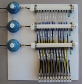
The flow board developed in the present study (Fig. 3) was based on a portable panel which can be easily fastened on surfaces with two upper screws or double-sided tape of large weight bearing capacity. All components of the flow board were carefully attached to the portable panel in order to avoid heights on its posterior side. Because of such characteristics, this portable flow board can be used with easiness and occupying minor areas of laboratories. The hanging of this instrument is done in a vertical way on walls or lab benches as well as inside of cold storage chambers.
flow board: three differential valves for precisely controlling the pressure of three gases; three
distribution tubes with 13 outputs; and 12 mixers for three different gases, e.g., N2, O2 and CO2.
Permanent components of the flow board
The three types of permanent component attached to the portable panel with the aid of screws were: differential regulators for fine pressure control of gas inflow, distributors (manifolds) with multiple outputs, and gas mixers.
The differential pressure regulators (Fig. 3, item 1) connected to the distribution tubes (Fig. 3, item 2) were fixed horizontally at the top of the portable panel and spaced vertically at a distance of 12 cm. The connection of each distributor was done with a pair of clamps for PVC tubes with 25 mm diameter screwed on bars with thickness of 5 mm. The purpose of the bars was to allow positioning of flexible tubes behind the rigid tube of the distributor, thereby facilitating the visualization of tubes connected to each distributor.
A total of 12 gas mixers were attached at the bottom of the portable plate (Fig. 2), each mixer presenting three inputs for different gases and one output to control the resulting mixed gas stream to be directed to a storage mini-chamber. Each input of the gases mixers was coupled to a tube containing a known flow of gas controlled by a restrictor.
Controlled atmospheres composed of one or two gases were obtained by closing the spare inputs of the mixer with flexible silicone corks. These corks were also used to close the spare outputs of the distribution tubes.
The permanent components of the flow board were screwed as counter-sunk holes, so as the head screws were completely inserted within the portable plate. The lack of heights at the posterior side of the flow board enabled its easy hanging on the surfaces of walls, lab benches and cold storage chambers.
The concentration of a single gas in the mixed stream, which is conducted to the
mini-chambers, as given as a molar fraction, i.e. the ratio between the flow of the gas (e.g. CO2) and the
sum of flows of all gases comprising the mixed stream. This molar, or volumetric, fraction can be
expressed as a percentage (e.g. 5 % O2 and 2 % CO2).
Temporary compone nts of the flow board
The permanent components of the flow board are added to the gas flow restrictors and other temporary components to enable the execution of the assays. The connectable parts of the flow board were: flow adjustment restrictors, silicone or latex-based tube segments and corcks, flexible tubes for gas transport, and storage mini-chambers for fruits and vegetables.
The flow adjustment restrictors were taken from a catalog of restrictors, prepared in advance typically with 200 or more restrictors for varying flows in order to permit the setup of the controlled atmosphere assays. The restrictors were calibrated and labeled with an air flow unit (L/h) at 25 ° C upon the typical working gradient of the flow board, which is 6 kPa. Thus, an atmosphere with 5 %
CO2 and 10 % O2 can be produced by connecting the first distributor tube to a 0.05 L/h CO2 flow
restrictor, the second distributor tube to a 0.10 L/h O2 flow restrictor and the third distributor tube to
a 0.85 L/h N2 flow restrictor, as an example. Technical details concerning the possibility of minor
or large adjustments due to variations of temperature or viscosity of the gases, such as CO2, O2, N2
or ethylene, respectively, are also considered in the stage of connection of restrictors between distributors and mixers.
Tube segments of flexible silicone or latex, with inner diameter of 4 mm and a length of approximately 30 mm were used to connect tubes, restrictors, distributors and mixers. These flexible segments were also used to splice the flexible tubes and to facilitate the gas sampling at the outflow of the storage mini-chambers.
5 mm and length of 10 mm. The corks were necessarily applied on the outputs of the distributors and gas mixers that were not connected to a flow restrictor.
The flexible tubes for transport of gases connected each gas mixer with its respective storage mini-chamber. In order to transport gases properly, the tubes were set to an internal diameter of 5 mm or larger, and lengths shorter than 2 m, in order to avoid significant gas counterpressures, which can reduce the gas flow calculated as a sum of flows of the mixed gaseous components. The connection of the flexible tubes to the gas mixers, flow restrictors or storage mini-chambers was done with the aid of segments tubes of flexible silicone or latex. Additionally, the gas transport tubes must present a low cost. The tubes referred to as spaghetti tubes produced from flexible PVC of various colors meet this requirement and are useful to reduce the amount of silicone tubes, which are more expensive. The use of colored flexible tube segments for gas transport facilitated and imparted a sense of organization to the experimental work, while reduced the possibility of erroneous couplings.
The most commonly used storage mini-chambers for studying fruits and vegetables are the wide-mouthed glass jars and the aluminum pressure pans, both presenting hermetic lids. For open flow experiments, these kinds of mini-chambers are equipped with two tubes at their bottom for inflow and outflow of gases. In the case of gas exchange studies, it is common to perform gas sampling at the outflow tube to estimate the steady respiration rate and ethylene concentration evolution, for instance. Specifically in this study, storage mini-chamber were mounted from aluminum pressure cookers whose lids received an orifice of 137 mm diameter on which a glass disk with thickness of 4 mm and diameter of 151 was glued. This optional glass plate was added to the lids to facilitate the inspection of the sample without needing to open the mini-chamber.
Control of pressure and distributors of gas flow
The differential valves used in this study and that permit a fine pressure tuning with respect to barometric pressure were valves frequently employed in lines and cylinders of liquefied petroleum gas cylinders (LPG). The internal spring of these effective and inexpensive valves were replaced to increase the operating pressure from the regular LPG value, which is 2.8 kPa, to the standard flow board value which is 6 kPa, as reported by CALBO (1989). This flow board pressure value was confirmed by connecting gas flow restrictors and one output of the distributor to a water column manometer, while the spring of the differential valve was tightened with a tuning screw until obtaining 60 cm of water column or 6 kPa of pressure.
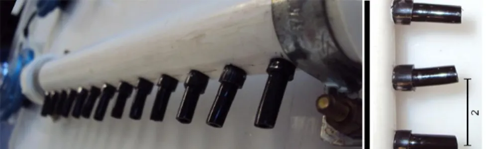
Each portable flow board device was equipped with three gas distributors (manifolds) fabricated from rigid PVC tubes with outer diameter of 25 mm and 28 cm long, and containing 13 parallel and separate outputs (Fig. 1) through flexible PVC tube segments with outer diameter of 5 mm, which were fixed with PVC tube rings, also flexible and with outer diameter of 6.4 mm and wall 1 mm thick. Twelve outputs were used to regulate the gases flows with the aid of standardized restrictors, and one output was set aside to check and/or adjust the working pressure of the differential valves.
To form the outputs of the distributor, the rigid PVC tubes were marked with orifices of 6.3 mm diameter, regularly spaced at 17 mm from each other. The ends of the rigid PVC tubes were closed with screwed lids. The outputs, made up of black flexible PVC tubes were fixed by clamping the flexible PVC rings which were previously inserted into the orifices. The output tubes had their ends moistened with soap and water and were cut into bezel, which facilitated the inclusion of the tubes into the rings with the aid of a plier. After fixation, the length of the output tubes was cut off to approximately 2 cm.
Preparation of the gas flow restrictors
The preparation of glass restrictors by thermo-molding under continuous air flow was performed on a flame of a Bunsen burner. The restrictors were submitted to a continuous internal air flow, whose variation during the manufacturing process was monitored in a capillary flow meter (Fig. 5).
The capillary flow meter apparatus has been earlier described by CALBO (1989), in which the flow (F) of the fluid, assumed to be incompressible, is proportional to the pressure gradient
(ΔP), which is measured by a referential restrictor (Fr) with the aid of a differential pressure
transducer or water column manometer with a U geometry, and two bifurcations (Fig. 5; equation 1).
F = Fr ΔP/ (ΔP0 –ΔP) (1)
where,
F is the flow;
ΔP0 is the differential of operating pressure (6 kPa or 60 cm water pressure column);
Fr is the air flow passing through the referential restrictor under ΔP0 pressure gradient, and
ΔP is the measured pressure gradient. The readings of pressure with the transducer in
millivolts were substituted directly in equation 1.
In the thermo-molding method, the air flow F modulated by the referential restrictor (Equation 1) is first reduced to a temporary value, after heating the capillary tube over the flame, leading its tip partially melted. This reduction of air flow is caused by the increase of temperature, which causes gas expansion and increases its viscosity. It can be proven by considering the Clapeyron equation, and the corresponding equation for viscosity of ideal gases (Atkins & Paula,
2008; Moore, 1972) that the relationship between the air flow at room temperature (T1) and the air
flow at the glass softening temperature (T2) is given by:
F2 = F1 (T1/T2)3/2 (2)
where,
F2 is the air flow measured with the restrictor at the glass softening temperature (~ 1024 K);
F1 is the air flow measured with the same restrictor after cooling to room temperature (~ 300
K);
T2 is the restrictor softening temperature under thermo-molding (~ 997 K), and
T1 is the room temperature (~ 300 K). In practical cases, the ratio between hot and cold air
flows given by Equation 2 is approximately equal to 0.165.
Hence, there is an initial reduction of air flow caused by heating during manufacturing of the restrictor (Equation 2), and then the air flow is further decreased when the diameter of the tip of the capillary tube is reduced to constricting values, according to [eq. (1)].
The capillary is immediately removed from the flame and the restrictor is considered to be ready when the air flow through the restrictor under thermo-molding is reduced to a value calculated by [eq. (2)]. This procedure allows forming a restrictor with deviation of 10 % of the target average value, when measured at room temperature (e.g. 300 K)
Equation 2 can be validated by the relationship between the air flow readings in mV of the heated capillary during the thermo-molding process and the air flow of the same restrictor after cooling to room temperature (e.g. 300 K). An important parameter in these procedures is the glass
softening temperature (e.g. 997 K), which allows determining that F2/F1 is equal to 0.165 in
Manufacturing of restrictors
The restrictors were prepared by thermo-forming method under continuous air flow using glass capillary tubes for micro-hematocrit tests (Fig. 5, item 6) with a diameter of 1.40-1.60 mm and a length of 75 mm. These tubes were cut in the middle and coupled to the restriction flow meter (Figure 5) by a flexible silicone tube 30 cm long and 1 mm internal diameter. The restriction flow meter was mounted from a differential pressure transducer (Freescale MPX 2010) and a millivoltmeter (electronic multimeter MINIPA® ET-2930).
The capillary tubes were molded by first adjusting the water column barostat to a height of 60 cm or 30 cm, depending on the flow range of restrictors to be molded in the flame. The pressure
gradient (ΔP) between the two inputs of the transducer (Fig. 5, item 5) is dependent on the air flow
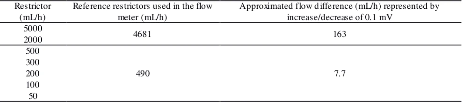
(F) passing through the capillary under molding (eq. 1). In the application of the thermo-forming method with continuous air flow, the reference restrictors (Fig. 5, item 4) of known flow (Fr) had the practical values specified in Table 1. The long and flexible silicone tubes facilitated exposure of the end of the capillary tube in a way progressive to the heating imparted by approaching the flame of the Bunsen burner. Restrictors with 5000, 2000, 500, 300, 200, 100 and 50 mL/h were produced to be used in the portable flow board operating with a pressure gradient of 6 kPa.
The manufacturing time for each restrictor was recorded together with the losses caused by sealing of the capillary tip (restriction). The flow was tested using a bubble flow meter pipette, in which soap diluted in water was used to follow the air flow, according to the movement of the meniscus or "soap bubble". These flows were measured using a pressure gradient of 6 kPa regulated with a barostat set at 60 cm water column. The direction of measurement (tube/tip) influenced on the flow measurement, and for this reason the labels of the restrictors were marked with an arrow in order to indicate the direction in which the air flow was measured.
The restrictors were inserted through the acetic silicone resin into the glass tubes with outer diameter 6.5 mm; length of 50 mm and thickness of 1 mm (approximated values). After curing of the silicone resin, the restrictors with diameter of 1.4 mm were inserted through the silicone rubber (Figure 7). The silicone rubber imparted a stable sealing and the glass tubes imparted easiness to connect, label, handle and seat in catalogs. The importance of these characteristics is easily perceived when the necessary couplings to use of the flow board in controlled atmosphere applications are taken into account, as displayed in Figure 4.
Method of the complementary restrictors
In order to preliminarily scrutinize the gas economy potential that the portable flow board developed in the present study provides in relation to the barostat flow boards with pressure adjustment by escape, a simulation test was carried out in which the differential valves were replaced by a controlling system equipped with a barostat of gas escaping through a water column.
For this simulation, a nitrogen gas cylinder with primary adjustment of the output pressure at the gas cylinder valve was used. The internal pressure of the flow board distribution tube was set at 60 cm water column, considering that the excess pressure in this case escaped through the barostat water column. The outlet pressure of the gas cylinder was adjusted to slightly exceed the water
pressure (60 cm) always, so that the pressure control was effectively done out by bubbling N2
through the water column of the barostat. As the primary valve of pressure adjustment in this simulation test had a double stage, the variation of the gas loss in the barostat after each repeated adjustments was assumed to be constant.
The simulation test was performed according to three different trials in which the total flow of the restrictors were respectively 48, 24 and 10 L/h. First, the initial setting of the pressure regulator of the gas cylinder was done to be slightly above 60 cm of water column. After adjustment of the inflow gas pressure, complementary restrictors were connected to the flow board in a number
appropriate values to annul the N2 bubbling through the water column of the barostat. The sum of
the exhaust valve of the flow board (barostat). All safety tests for barostat flow boards were performed in triplicate.
RESULTS AND DISCUSSION
The high sealing degree of the permanent components of the portable flow board was confirmed by the absence of bubbling in the distributors and mixers tested by air pressurization and further immersion in water before mounting the flow board. The method of silicone rings at the distributor outputs and tightened insertion of copper tube segments in the mixers guaranteed a suitable tightness to the flow board, thereby eliminating the need for additional sealing procedures. This sealing efficiency in the portable flow board was essential to the preparation of gaseous atmospheres with known composition in studies about controlled atmosphere and works involving estimates of respiration and evolution of ethylene.
In laboratory and cold chambers, in which studies involving repeated treatments in storage mini-chambers are conducted, the flow board device was hanged in a simple, stable and not permanent way over walls and lab benches with the aid of double-sided tape or screws, which improved the rational use of the working area and served as an evidence of the portability of the flow board.
Preparation of the gas flow restrictors
The linear calibration curve in Figure 6 indicated the precision of equation 2 and facilitated the application of thermo-molding method with continuous air flow to manufacture the gas flow restrictors. The linearity of the curve was the simplest indication of the quality of the proposed method for the production of glass restrictors with values specific to the need of the researcher.
The average manufacturing time for the restrictors was 51 seconds per unit, and the percentage of values within a range of ± 10% of the target value was of 45 %. Theoretically, this result can be improved, but still can be considered satisfactory, especially for enabling the production of restrictors in a wide range, which is useful for applications in controlled atmospheres and gaseous exchanges in open systems (flow board). In the restrictors manufacturing process, the labeling of the flows measured and recorded exhibited a standard error of ± 2 %.
During the thermo-forming process, it was observed that the use of the reference restrictor of 4681 mL/h and input pressure of 60 cm water column in the barostat, the flow caused expansion of the capillary, thereby becoming spherical and useless. To avoid this problem, the restrictors for flows greater than 2000 mL/h were manufactured using 30 cm of water column pressure in the barostat (Fig. 5, item 2).
More than 300 restrictors with various flows (5000 mL/h, 2000 mL/h, 500 mL/h, 300 mL/h, 200 mL/h, 100 mL/h, and 50 mL/h) were prepared in this study, which have been used in experimental tests of gas exchange and controlled atmosphere in the postharvest laboratory. The right compositional adjustment of the controlled atmospheres also indicated that the restrictors were mechanically resistant, easy to handle and afford a precise control of gases flows. Although the restrictors made from capillaries for micro-hematocrits could be directly used, their setting in larger tubes provided great robustness, ease of handling and practical labeling.
The gas flow through the restrictors can be approximately described by Poiseuille's Law (Equation 3), which is applicable for the flow of fluids considered to be non compressible and in laminar flow regime.
F = (ΔP π R4) / 8 η l (3) where,
F is the flow;
ΔP is the pressure gradient through the restrictor;
R is the radius,
The restrictors produced in this study were calibrated using atmospheric air. However, the restrictors can also be used to control flow of other gases, and according to the Poiseuille's law (Equation 3), it is necessary to perform corrections of flow proportional to the viscosity of each gaseous component.
Economy of gases
The simulation of the magnitude of gas economy expected with the use of the portable flow board developed in the present study in relation to the traditional barostat flow boards was performed with basis on the method of additional restrictors. Under the conditions of simulation, the system mounted with pressure adjustment through barostat water column displayed an additional gas consumption of approximately 10 liters per hour. Therefore, the use of flow boards with closed
differential valves for pressure, as the system described here, is confirmed to substantially reduce
the cost of research related to controlled atmospheres. Another relevant aspect is that the method of supplementary restrictors is useful to regulate the exhaust flow in traditional flow boards that operate with gas exhaust barostats. This type of control is important to maintain the loss of gases strictly within the limits that ensure the correct operation of these systems. In other words, additional restrictors enable settings wherein there is no shortage of pressure and flow on one hand, or waste and cost increasing of research on the other hand.
The flow board and restrictors produced in this study are a quality solution that combines simplicity and precision to support researches about gas exchange and controlled atmospheres for fruit and vegetable. In comparison to traditional barostat flow boards, as described by various authors (CRISOSTO et. al., 1993; RINALDI et. al., 2008; CASTILLO PIZARRO, 2009; SANTANA, 2009; CUNHA JUNIOR et. al., 2012) the flow board system developed in this study is more economical.
From a reliability point of view, it is worth mentioning that the portable flow board is very similar to other barostat flow boards that have been used for studies about controlled atmospheres and post-harvest physiology studies of fruits and vegetable in open and continuous flow systems (CLAYPOOL & KEEPER 1942; CALBO, 1989). The aspects that differentiate the portable flow board over the traditional flow boards with air escape through barostat water column are:
a) After adjustment, the differential valves with no gas escape (Fig. 3, item 1) perform a strict control of pressure, with variation smaller than 0.05 kPa, while the inflow pressure set at the primary pressure regulator of the compressed gas cylinder varies between 50 and 100 kPa. In the barostat system with gas escape through the water column, the control of input pressure from the cylinder must be precise to avoid substantial waste of gas. This is a common occurrence in the traditional system, since the total flow of a gas component directed to the barostat is modulated by a manually adjusted needle valve.
b) In the pressure control system with barostats, researchers a lso need to be attentive to the evaporation of water, which must be replenished daily with the care to prevent any reduction of the water levels that cause variations larger than 0.05 kPa in the adjusted pressure.
c) The severity of the counterpressure problem in open system with barostat or pressure differential valves, if adjusted to the same working pressure of 6.0 kPa, is clearly equal. Nevertheless, the differential valve system with pressure adjustment by screw and spring described here facilitates the use of larger input pressures, which can be used to make the counterpressure proportionally less relevant in particular cases. The counterpressure in tubes submitted to laminar flow, according to the equation of Poiseuille (Eq. 3) (MOORE, 1972), depends on the fourth power of the radius, or the tube diameter, and is proportional to the adjusted flow in the controlling restrictor.
In addition to using a consolidated procedure for adjustment of flows and concentrations, thanks to numerous works on analogous barostat flow boards (ClAYPOOL & KEEFER, 1942; CERQUEIRA, 2012), which provides safety, the flow board system described in the present study further makes use of glass restrictors which are well-known for being stable. Therefore, the changes performed on this portable flow board play a major role in the gases economy and facilitate the production of the restrictors with a wide range of working gas flow. These characteristics are indispensable both for barostat flow boards and flow boards that operate with adjustable and closed valves for gas pressure tuning.
FIGURE 1. Side view of the gas distributor tube with outputs fixed by rings (left). Figure with no defined scale. Detailed view of the connection of the plastic tubes outputs inserted into the orifices of the hard PVC distributor tube with the aid of rings made up of flexible
PVC tube segments (right). Scale is centimeters.
FIGURE 2. Gas mixer. Schematic representation (left). Right photo of the gas mixer with nylon
body and connections made up of copper segments 4.75 mm diameter (right). Scale in millimeters.
FIGURE 3.Photo of the portable flow board. 1 - Differential valve to control inflow gas pressure in
the distributor with pressure regulator by internal spring tightened by screw; 2 - gas
FIGURE 4. Portable flow board for use in controlled atmospheres by feeding from gas cylinders and further coupling to storage mini-chamber.
FIGURE 5. Schematic of manufacturing of gas flow restrictors by thermo-forming method under continuous hot air flow. In this system, the tip of micro-hematocrit-type glass capillary tubes, are manually exposed to a flame while the flow reduction caused by shrinking of the capillary tip is monitored with a flow meter. The system particularly used in this study was composed of: 1 - Air compressor; 2 - barostat water column to control air pressure by escape; 3- Millivoltmeter; 4 - Reference flow restrictor; 5 - Air pressure transducer; 6 - Capillary tube during the thermo-forming process over a flame; 7- Bunsen burner.
FIGURE 7. A) Restrictors manufactured by the thermo-forming method with flame. B) Restrictor inserted into larger glass tubes preliminarily filled with cured silicone rubber. C)
Restrictor with label. Millimeter scale.
TABLE 1. Reference restrictors and sensibility imparted to the flow meter.
Restrictor (mL/h)
Reference restrictors used in the flow meter (mL/h)
Approximated flow d ifference (mL/h) represented by increase/decrease of 0.1 mV
5000
4681 163
2000 500
490 7.7
300 200 100 50
CONCLUSIONS
1. The portable flow board is a low cost and simple post-harvest equipment that allows preparing controlled atmospheres in open systems with stable composition and flow, in a manner similar to traditional flow boards with control of gas escape by barostats.
2. With control of pressure by closed differential valves, the portable flow board economizes gas compared with flow boards equipped with gas escape water column barostats.
3. The portable flow board occupies smaller areas and can be installed more easily than non-portable flow boards.
4. The thermo-forming method with continuous air flow is simple and provides an alternative to produce numerous durable and labeled gas flow restrictors with a wide range of specified flows.
5. The portable flow board described here is capable of controlling the composition of mixtures containing more than three gases, by using additional distributors and adding supplementary gas inputs in the gas mixer.
REFERENCES
ATKINS, P. & PAULA, J. Físico-química. Tradução: Edilson Clemente da Silva et. al. 8. Ed. Rio
de Janeiro: LTC, 2008. 589p.
BENGTSSON, G.B.; HAGEN, S.F. Storage and handling of fruit and vegetables for optimum
health-related quality. In: TOMÁS-BARBERÁN, F.A. & GIL, M.I. Improving the
health-promoting properties of fruit and vegetable products. Cambridge: CRCPress, Wood-head
Publishing Limited, 2008. p.412-430.
CALBO, A.G. Adaptação de um fluxcentro para estudos de trocas gasosas e um método de aferição
CASTILLO PIZARRO, C.A. Avaliação de morangos submetidos a resfriamento rápido e
armazenamento em diferentes embalagens e temperaturas. 2009. 58f. Tese (Doutorado em
Engenharia Agrícola) - Faculdade de Engenharia Agrícola, Universidade Estadual de Campinas, Campinas.
CLAYPOOL, L.L. & KEEFER, R.M. A colorimetric method for CO2 determination. Proceedings
of The Americam Society for Horticultural Science, v. 40, p.177-186, 1942.
CERQUEIRA, T.S. Fisiologia, bioquímica e conservação de bananas e goiabas sob altas
concentrações de O2 combinadas com CO2 e N2O. 2012.127f. Tese (Doutorado em Ciências) –
Escola Superior de Agricultura “Luiz de Queiroz”. Universidade de São Paulo, Piracicaba.
CRISOSTO, C.H.; GARNER, D.; DOYLE, J.; DAY, K.R. Relationship between Fruit Respiration,
Bruising Susceptibility, and Temperature in Sweet Cherries. Hortscience, v. 28(2), p. 132-135,
1993.
CUNHA JUNIOR, L.C.; JACOMINO, A.P.; TREVISAN, M.J.; SCARPARE FILHO, J.A. Altas
concentrações de oxigênio favorecem a conservação de morango 'Oso Grande'. Revista Brasileira
de Fruticultura, Jaboticabal, v.33, n.4, pp. 1074-1083, dez. 2011.
CUNHA JUNIOR, L.C.; JACOMINO, A.P.; OGASSAVARA, F.O.; TREVISAN, M.J.; PARISI, M.C.M. Armazenamento refrigerado de morango submetido a altas concentrações de
CO2. Horticultura Brasileira, v. 30, n. 4, p. 688-694, out./dez. 2012.
MOORE, W.J. Physical chemistry, London: Freeman, 1972. 977p.
RINALDI, M.M.; BENEDETTI, B.C. & MORETTI, C.L. Atividade respiratória, produção de
etileno e vida útil de repolho (Brassica oleracea, var. capitata) minimamente processado em
atmosfera controlada. Engenharia Agrícola, Jaboticabal, v. 28, n. 3, p. 579-589, jul./set. 2008.
SANTANA, L.R.R. Qualidade pós-colheita de pêssego 'Douradão' sob atmosfera controlada e
modificada. 2009. 176f. Tese (Doutorado em Engenharia Agrícola). Faculdade de Engenharia