Integrated Experimental Approach for Alloying of Surface Layer Ti6Al4V+B
4C Metal
Matrix Composites using Laser Treatment
Musibau Olalekan Ogunlanaa*, Esther Titilayo Akinlabia , Mutiu Folorunsho Erinoshoa,b ,
Oluwagbenga Temidayo Johnsonc, Oluseyi Philip Oladijod
Received: May 24, 2018; Revised: October 24, 2018; Accepted: November 23, 2018
Surface engineering applications have brought the titanium and its alloys into the limelight in the manufacturing industries such as the aerospace, automobile, marine, chemical processing industry, nuclear power and biomedical. Despite the growths experienced in the use of this material, it is plagued with poor wear behaviour, especially when in contact with other materials during application. In this research work, the reinforcement of titanium alloy (Ti6Al4V) and boron carbide (B4C) ceramic powders was employed to form the Ti6Al4V+B4C composites. The effect of laser power on the micrograph, microhardness, surface roughness and wear has been investigated. The micrographic evaluation, the geometrical analyses and the effect of laser power on the width and height of deposit, aspect ratio and dilution rate were also evaluated. The highest aspect ratio of 5.31 and dilution rate of 63.81 % was observed in sample MB5 deposited with a laser power of 2400 W. The dry sliding friction and wear conducted using a 10 mm diameter tungsten carbide ball and a normal load of 25 N revealed that sample MB2 produced at a laser power of 1800 W has the lowest wear depth and wear width of 74.6 µm and 1080.77 µm. From the lowest COF attributed by sample MB5, it can be inferred that coefficient of friction does not determine the wear loss due to the sticking of some wear debris to the wear track during sliding action. Thus, other wearing factors are also considered for the wear loss evaluation.However, this composite can be used for the repair of the worm part of a rotating shaft and turbine blades.
Keywords: AFM surface morphology, boron-carbide, dry sliding wear, metal matrix composites, micrograph, microhardness, Ti6Al4V alloy.
*e-mail: [email protected].
1. Introduction
This research paper investigates the extensive experimental approach of titanium alloy and boron carbide composites for surface engineering applications using laser treatment. Titanium and its alloys are widely used in the engineering and biomedical industries due to their specific properties which include: lightweight, high strength-to-weight ratio, corrosion resistance, and excellent high-temperature properties 1-3. However, Ti6Al4V alloy plays a major role
in the blades, disc and the cooler parts of the compressor in jet engines because high strength and creep resistance are required in these applications. There is increasing use of Ti6Al4V alloy for quite critical applications for the forged structural members in aerospace; including undercarriage components, flap, and slat tracks in wings, and in addition, for engine mountings 3-6. On the other hand, boron carbide,
B4C has found several applications, such as grinding wheels for sharpening cutting tools, super-abrasive in polishing, and
as well as armour materials. Boron carbide is recognized as the third hardest material behind diamond and cubic boron nitride (C-BN). It is, however, possesses attractive properties which include: high melting point, low specific weight and thermal expansion, the high cross-section for absorption of a neutron, and outstanding wear and corrosion resistance 7-11.
Furthermore, laser treatment is an additive manufacturing (AM) process such as laser metal deposition (LMD), laser additive manufacturing (LAM), or selective laser melting (SLM) whereby a product is formed by melting successive layers of powder, e.g. titanium alloy grade 5 (Ti6Al4V) powder, through the interaction of a laser beam. Upon irradiation, the powder material is heated and, if sufficient power is applied, melts and forms a liquid pool onto the surface of the substrate. Afterwards, the molten pool solidifies and cools down quickly, and the consolidated material starts to form the anticipated product 12. Due to the high reactivity
of titanium alloys, the process needs to be conducted under an inert argon atmosphere. Thus, the quality clad layer can be achieved through an integrated metallurgical bonding
aMechanical Engineering Science Department, University of Johannesburg, P O Box 524, Auckland
Park Kingsway Campus, Johannesburg, South Africa
bMechanical and Industrial Engineering, University of Namibia, P.O. Box 3624, Ongwediva, Namibia
cDepartment of Mining and Metallurgical Engineering, University of Namibia, P.O. Box 3624,
Ongwediva, Namibia
dChemical, Material and Metallurgical Engineering Department, Botswana International University of
and low dilution. If the correct parameters are not adopted, the above requirements may not be satisfied 13. If the melt
pool is severely diluted during deposition, the properties of the clad layer will be influenced by defects such as cracks, porosity, and lack-of-fusion after solidification. Therefore, using metallic powders as a deposition medium would, however, produce fully functional parts with processes like Laser Metal Deposition (LMD) or Laser Engineered Net Shaping (LENS), and Direct Metal Deposition (DMD) 14.
Moreover, titanium alloys can be boronised efficiently to increase hardness and wear resistance. Effect of laser alloying of B4C powder with Ti6Al4V alloy powder for LMD process has been studied. Laser boronising of Ti6Al4V alloy brings about an increase in hardness of surface layer almost twice as titanium alloy substrate. The alloyed zone was free from cracks and porosity at higher laser power. The results of these investigations revealed the formation of TiB and TiB2. Therefore, the superficial layer consisted of a relatively ductile solid solution and dispersed titanium borides, thereby causing both surface hardening and increased wear resistance. Titanium-Nickel based composite reinforced with TiC and TiB2 were formed on Ti6Al4V alloy substrate via a laser cladding process. Different contents of B4C were added in
various proportion (0 wt%, 5 wt%, 15 wt%, and 25 wt%). The increase in B4C content was reported to improve the laser absorption rate of the clad and as well as promoting the melting of the substrate which in turn increased the dilution rate. The average microhardness of the coatings was also reported to increase as the B4C content was increased 15.
The agglomeration of boron carbide (B4C) and cubic boron nitride (cBN) was reinforced with Ti6Al4V metal matrix composites by direct metal laser sintering. The density of the sintered composite samples of matrix Ti6Al4V alloy with the reinforcement of cBN and B4C was revealed to be dependent on the scanning speed, power density and the percentage of the reinforcement. The addition of the B4C and cBN was also reported to decrease the overall density of the formed metal matrix composite 16. The properties of
sintered B4C-TiB2 composites were investigated and the grain growth of the boron carbide was reported to increase the fracture strength. The mixture of boron carbide, titanium diboride and other additive was also revealed to improve the mechanical properties and microstructure of the formed composites 17. Different masses of boron carbide (0.64, 1.28,
2.55 and 5.11 g) were sintered with titanium carbide for densification behaviour and mechanical properties. It was reported that by removing the oxide impurities, the boron carbide could lower the onset temperature for rapid grain growth of TiC. However, the specimen sintered with 5.11 g of boron carbide had the maximum fracture toughness of 4.79 ± 0.50MPa m1/2 and flexural strength of 552.6 ± 23.1
MPa 18. The selective laser melting of a high-energy ball
milled Ti - B4C powder was investigated. It was revealed that boron carbide reacted in the melt pool with titanium to
form titanium boride and titanium carbide. A low dilution between the substrate and the participating powder materials was reported to be required for correct mixing ratio of the elements. However, sufficient energy input is required to assure a complete melting of the B4C-particles 19. The B
4C is
a ceramic which has a high melting point, excellent hardness, good mechanical properties, low specific weight and great resistance to chemical agents 20. However, unlike other
ceramic and metallic materials, the mechanical properties of the B4C strongly depend on the chemical compositions, the microstructural behaviour as well as the fabrication processes 21.
In this paper, extensive experimental descriptions of laser alloying are successfully carried out. However, a solid metallurgical bonding between the clad layer and the base metal with moderately low dilution are realised. The surface and the cross-sectional analyses of the cladded Ti6Al4V+B4C composites were investigated over the process parameters and similarly conducting investigations on their micrographs, phase composition, microhardness, AFM surface roughness and wear characterizations respectively.
2. Material and Methods
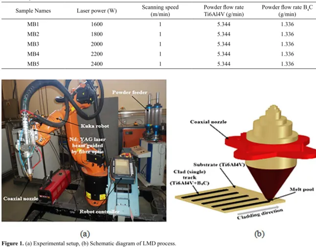
The materials used for this research work are Ti6Al4V alloy and B4C powders at the weight ratio of 80 wt % to 20 wt %. The Ti6Al4V alloy substrate used was sandblasted and cleaned with acetone prior to the coating operation. The laser powers used were varied from 1600 W to 2400 W while keeping the scanning speed constant at 1 m/min. Tables 1 and 2 depict the chemical composition of Ti6Al4V alloy and B4C.
During the surface melting process, the powders were dissolved in the melt pool and thus led to the alloying of the surface with the substrate. The laser equipment is highly sophisticated and it was designed to operate at a maximum power of 3000 W. The melt pool was created on the substrate at varying laser powers with constant scanning speed, powder flow rate, and gas flow rate respectively as designated in Table 3. The prepared samples were characterized to determine the micrographic geometries, microhardness, and wear behaviours as well as the AFM surface roughness. To prevent atmospheric contamination of the melt pool, argon gas was supplied at 10 l/min. The geometry of the laser melted zone was determined by transverse sectioning and proper measurement. Mounting, grinding and polishing exercise was done on the lateral view of the samples. Etching was also done on the mounted samples using the Kroll’s reagent with the mixture of 100 ml H2O; 3 ml HF; and 6 ml HNO3 respectively.
Table 1. Chemical composition of Ti6Al4V alloy. 22
Element Al V C Fe O N Ti
Composition (%) 6 4 < 0.08 < 0.30 < 0.20 < 0.07 Balance
Table 2. Chemical composition of B4C. 23
Element B C B2O3 Fe Si
Composition (%) 74 - 79 17 - 24 0.1 - 1.0 0.2- 0.5 0.1- 0.3
Table 3. Experimental matrix.
Sample Names Laser power (W) Scanning speed
(m/min)
Powder flow rate
Ti6Al4V (g/min)
Powder flow rate B4C
(g/min)
MB1 1600 1 5.344 1.336
MB2 1800 1 5.344 1.336
MB3 2000 1 5.344 1.336
MB4 2200 1 5.344 1.336
MB5 2400 1 5.344 1.336
Figure 1. (a) Experimental setup, (b) Schematic diagram of LMD process.
Figure 2. Physical appearance of the Ti6Al4V+B4C deposits with respect to laser power.
The micrographic analysis of the alloyed samples was carried out using the Olympus BX51M optical microscope. The Vickers microhardness measurements were conducted on the cross-section of the deposit. Phase composition with X-ray diffraction was also examined using Rigaku ultima IV with CuKα radiation. Wear analysis was done using the ball-on-disc tribometer while the surface roughness topography was analysed using the Veeco Di3100 atomic force microscope (AFM) machine.
3. Results and Discussion
The physical appearance of the laser deposited Ti6Al4V+B4C composites is illustrated in Figure 2. The micrograph of the alloyed surface is observed to have coarse grain structures and
on the substrate were, however, characterized with a desirable melt pool and good deposited laminate as the laser powers were constantly increased.
Where:
LP = laser power, W SP = scanning speed, m/min PFR = powder flow rate, g/min GFR = gas flow rate, l/min
The surface of the melted tracks shows the characteristic appearance and their level of homogeneity are revealed in the microstructure. Figure 3 shows the micrograph of the deposit. The micrographic investigations revealed the presence of two typical zones obtained under the laser treated areas: alloyed zone (AZ) and heat-affected zone (HAZ).
The micrograph and phase composition development, which determines the properties of the melted zone, can be attributed to the following conditions:
• High heating at low speed of convection stream provides uniform distribution of B4C and Ti6Al4V in the molten pool;
• Lower speed and sufficient cooling process; • Preferably, rapid heating and cooling after the
laser deposition process enhance good bonding but susceptible to defects such as cracks due to the high residual stress resulting from the high heating and cooling rate.
The microstructural analysis revealed that the content of boron carbide particles in the composites was formed on the top layer of the deposit which actually behaves like a shielding structure or coated film-like structure on the deposits surface. This, however, serves as the properties that are responsible for the resistance to wear enhancement due to the higher concentration of boron carbide particles deposited at the utmost surface of the deposit and further characterized by the martensitic microstructure. This was reported elsewhere 24.
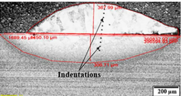
The dilution analysis of the deposits was observed with the aid of the optical microscope by measuring the height, width, and area of the clad as well as the heat affected zones for each deposition in order to determine the dilution rate. In order to study the effect of laser power on the dilution rate, the thickness of composite and dilution layers were measured from each sample at low magnification using the
optical microscope. Thus, for single laser track geometrical characterization, the main variables of the cross-section were measured as illustrated in Figure 4.
These variables were given as clad height, H (µm); clad width, W (µm); clad area, Ac (µm2); and molten area,
Am (µm2). Similarly, the heat affected zone height and
the width were also measured. Dilution, as well as aspect ratio, was calculated according to the expression given in equations 1 and 225.
(1)
And aspect ratio, AR,
(2)
Where: D = Dilution Am = Molten area Ac = Clad area AR = Aspect Ratio W = Clad width, and H = Clad height
The AR is described as the quantity which is related to the appearance of porosity and crack in the overlapping tracks. Therefore, in order to ensure a good overlapping, the aspect ratio between 3 and 5 is recommended 25. Figure 5
presents the measurement and geometry for a deposited sample whereas Table 4 shows the geometrical quantities of single laser tracks carried out under the dilution analysis.
The geometries of the cross-sectional view of the deposits from samples MB1 to MB5 are tabulated. The height, width,
Figure 3. Micrograph of full single track deposit, magnification 50x.
Figure 4. Schematic view of the cross-section of laser tracked deposit.
D
A
A
A
100
c m
m
#
=
+
AR
H
W
=
clad area and the heat affected zone of the deposit are measured on the optical microscope. The measurements for all the deposited samples were highlighted in Table 4. The clad width and the molten area increase as the laser power was increased. The aspect ratio was also increased except sample MB3 that shows a slight drop in the aspect ratio.
These obtained values suggest that dilution rate is increased with the increase in the laser power. Although, as reported by Bai et al, increase in B4C content is responsible for the increase in the dilution rate of a deposition process. However, the dilution rate is related to the processing parameters such as scanning speed, spot diameter, and thickness of the preplaced layer and the inherent properties of the cladding and substrate materials 15.
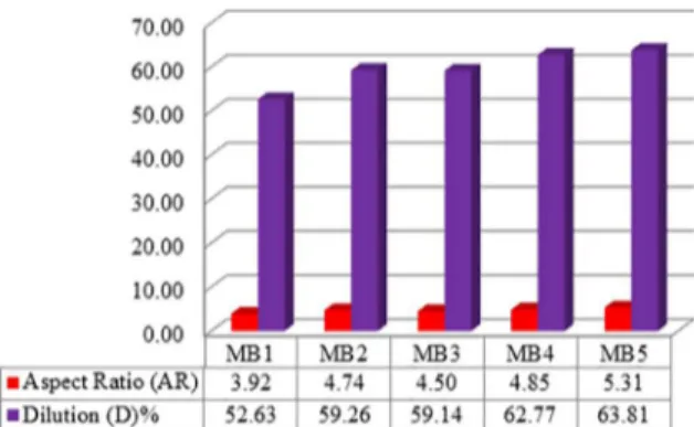
Thus, Figure 6 shows the behaviour of each sample for both the aspect ratio and the dilution rate as the laser power of the coating was increased from samples MB1 to MB5 respectively.
From the preliminary optimization tests, samples MB1, MB2, MB3, MB4 and MB5 corresponding to the laser power of 1600 W, 1800 W, 2000 W, 2200 W and 2400 W respectively were observed with aspect ratio from 3.92 to 5.31 and dilution rate from 52.63 % to 63.81 %, thus, they have reflected the best in terms of an imperfection in the internal structure after solidification for the combined acceptable geometrical characteristics. However, the dilution rate of above 50 % was observed across the samples due to the unmelted boron carbide particles in the melt pool after solidification. Furthermore, laser radiation has an impact on phase transitions of the powders and background-remelted layers as a result of the adequate density of the laser power.
The highest aspect ratio of 5.31 and dilution rate of 63.81 % was observed in sample MB5 deposited with a laser power of 2400 W. This high laser power has a significant effect on the volume of the deposited composite.
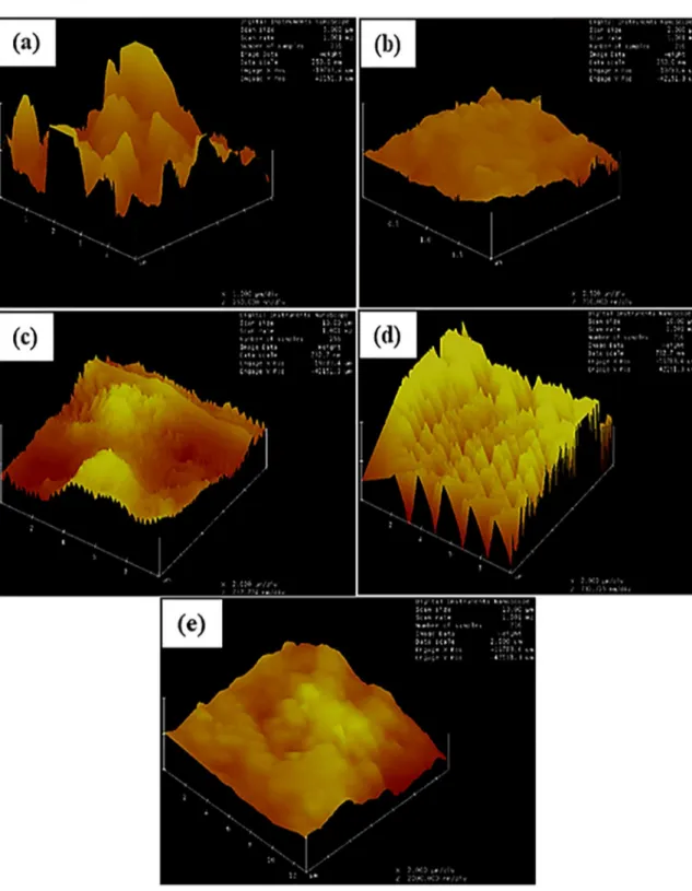
The surface of the melted tracks (Figure 2) illustrated the characteristic appearance in which the atomic level characterization of the coatings is determined through the surface roughness by the AFM images are presented in Figures 7 (a) to (e).
The AFM analysis revealed that the surface roughness (Ra) was varied with respect to the laser powers. Table 5 presents the surface roughness, as well as the grain size of various laser deposited samples observed in this study.
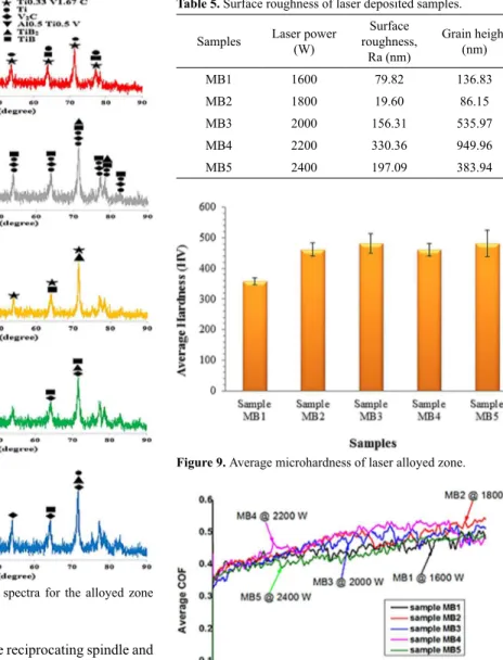
The Ra values are not consistent and this behaviour could be as a result of the cooling rate and the depositing environmental condition at the time of each operation. With respect to the different laser power used, the trend of the surface roughness on the deposited samples varies as a result of the different particle sizes of the participating powders as well as their distribution in the melt pool. The X-ray diffraction analysis was performed on the surface of laser melted tracks. The XRD spectra presented in Figure 8 shows that the phases were characterized by the increase in the diffraction patterns peak intensity of the coatings as the laser power was increased. These results, however, suggest that the coatings were composed of slightly low traces of impurities or no irregular impurity of crystalline.
Thus, the crystalline phases such as titanium vanadium carbide (Ti0.33V1.67C); titanium boride (TiB); and titanium (Ti) are profound in the spectra.
The microhardness profiling of the composites was measured on the surface at the different depth of laser alloyed layers. Figure 9 presents the microhardness values together with their corresponding standard deviations. Vickers hardness values of the composites were however measured under the load of 4.9 N at a dwell time of 15 seconds on a digital microhardness tester.
The average microhardness of the alloyed zone with the standard deviation was evaluated for each sample. It was discovered that the hardness value increases as the laser power was increased. This happens from sample MB1 to MB3, and decreased at sample MB4 and afterwards increased again for sample MB5 deposited at laser power of 2400 W. Although, in the overall profiling, sample MB5 was observed to have Figure 6. Plot of Aspect Ratio and Dilution Rate for the deposited
Ti6Al4V+B4C composite.
Table 4. Geometrical quantities of single laser tracks.
Sample Names Clad width x10
3
(µm)
Clad height x103
(µm) Aspect ratio
Molten area x106
(µm2)
Clad area x106
(µm2)
MB1 1.45 0.37 3.92 0.40 0.36
MB2 1.47 0.31 4.74 0.48 0.33
MB3 1.53 0.34 4.50 0.55 0.38
MB4 1.60 0.33 4.85 0.59 0.35
Figure 7. AFM images of laser deposited Ti6Al4V+B4C composite (a) Sample MB1 deposited at laser power of 1600 W; (b) Sample
MB2 deposited at laser power of 1800 W (c) Sample MB3 deposited at laser power of 2000 W (d) Sample MB4 deposited at laser powers of 2200 W and (e) Sample MB5 deposited at laser power of 2400 W.
the highest peak of hardness value and on average, it still has the highest average hardness of 481±43 HV. Thus, the variation in hardness values set as criteria to improve the ductility property of the alloyed layer.
The wear test was conducted on the deposited samples using the dry sliding wear process on ball-on-disc tribometer
25 N. Thus, the frequency for the reciprocating spindle and the speed were maintained at 5 Hz and 5 mm/s respectively throughout the test. Figure 10 shows the COF behaviour for the entire laser deposited Ti6Al4V + B4C samples.
The COF values for the tests were observed to be between 0.50 and 0.56 in which samples MB1 and MB5 have the lowest value of COF corresponding to 0.50 with respect to time. Furthermore, the COF values remained between the range of 0.3 and 0.56 throughout the test. The COF has an influence on the deposited composites. The enhanced properties with high microhardness, low friction coefficient, and excellent wear resistance of the alloy were attributed to the formation of hard ceramics compounds in the Ti6Al4V alloy. The dry sliding wear tests were carried out on the single track deposited samples of Ti6Al4V+B4C composites according to the ASTM G133-05 26. Figure 11 shows the
SEM micrograph of a wear scar having the wear width and stroke length. These were introduced on the surface as a result of the back and forth movement of the tungsten ball. Conversely, Table 6 presents the wear measured variables on the alloyed surface for every sample.
Figure 8. X-ray diffraction (XRD) spectra for the alloyed zone
with phase identification.
Table 5. Surface roughness of laser deposited samples.
Samples Laser power (W)
Surface roughness,
Ra (nm)
Grain height (nm)
MB1 1600 79.82 136.83
MB2 1800 19.60 86.15
MB3 2000 156.31 535.97
MB4 2200 330.36 949.96
MB5 2400 197.09 383.94
Figure 9. Average microhardness of laser alloyed zone.
Figure 10. COF of laser deposited samples at different laser powers.
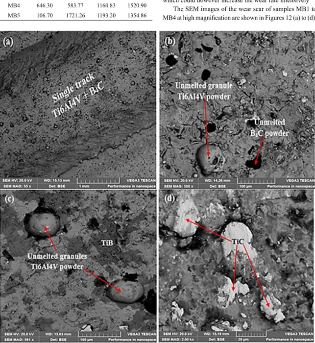
Figure 12. SEM images of the wear track of sample MB1 to MB4. The measurements illustrate the behaviour of wear depth, wear radius, wear width and stroke length for the deposited samples. Of all the deposited composites, sample MB2 deposited at the laser power of 1800 W was identified to have the lowest wear depth and wear width of 74.6 µm and 1080.77 µm. Thus, sample MB2 was associated with
profound ductile property compared to every other sample. Uneven distribution of the B4C in that region might be the cause of the behaviour of the lowest wear depth and wear width among the rest of the samples. However, sample MB5 has the highest wear width of 1193.20 µm and the wear depth of it is more than that of samples MB1, MB2 and MB3 respectively. The lowest COF exhibited by sample MB5 could be as a result of the wear debris being congested on the wear track during the sliding operation. Thus, the COF is not actually the determining factor for the wear loss or volume. Other factors such as the wear width, wear radius and depth are also considered. The large wear depth of 646.3 µm exhibited by sample MB4 could be as a result of some internal porosities inside the deposited composite which could however increase the wear rate intensively 27.
The SEM images of the wear scar of samples MB1 to MB4 at high magnification are shown in Figures 12 (a) to (d). Table 6. Wear scar measurement and variables evaluation.
Samples
Wear depth, hf
(µm)
Wear radius, Rf
(µm)
Wear width, w
(µm)
Stroke length, Ls
(µm)
MB1 86.40 1852.32 1118.24 1452.57
MB2 74.60 1994.51 1080.77 1459.70
MB3 86.60 1976.43 1157.27 1425.22
MB4 646.30 583.77 1160.83 1520.90
Wear ridges and ploughs are initiated on the worn surface as a result of the abrasive wear. Wear debris were rooted to the side of the scar thereby creating the particles of both powders. The width and depth of the wear scar are different for each sample and with respect to the laser power. The unmelted B4C in the deposit has also affected to the depth of wear thereby improving on the wear properties of the primary alloy. Some unmelted TiC was also observed in the crushed zone and allows the clustering of the Ti6Al4V alloy to be embedded and create a martensitic phase within the scar region. Some cracks of the Ti6Al4V alloy were also found on the scar which was initiated as a result of the unmelted B4C during the back and forth of the crusher (tungsten carbide ball).
4. Conclusion
Laser deposition process has been employed for the operation that involves the agglomeration of the two participating powders (Ti6Al4V and B4C). The depositions and characterizations of titanium alloys and boron carbide metal matrix composites on titanium alloy substrates were investigated. The following conclusions were deduced from the results:
• The geometrical analysis of the samples revealed that the aspect ratio and the dilution increase with an increase in the laser power.
• There was a relationship between the intermetallic phase of α+β titanium alloy and boron carbide at the peaks between 40.69o and 71.57o. The XRD
patterns of the deposited composites revealed the presence of intermetallic compounds at the deposit-interface counterpart.
• The coefficient of friction has an influence on the deposited Ti6Al4V+B4C composites. Sample MB5 deposited at a laser power of 2400 W respectively was observed with the lowest COF.
• The properties of the composites with a high microhardness, low friction coefficient and excellent wear resistance were attributed to the formation of hard ceramics compounds created in the phases of the primary alloy. However, with the results obtained, the properties of the Ti6Al4V alloy has been improved and justified with the addition of B4C.
• The laser cladding composite with the lowest COF is not characterized by fair resistance to wear damage when considering other wear factors, for example, the wear width, wear radius, wear length and depth. • Sample MB2 deposited with a laser power of 1800
W depicted the lowest surface roughness and grain height of 19.60 µm and 68.15 µm.
5. Acknowledgements
This research work is supported by the National Research Foundation, Pretoria, South Africa and the National Commission on Research Science and Technology, Namibia on a collaborative project. Appreciation also goes to the Global Excellence Stature (GES).
6. References
1. Filip R. Alloying of surface layer of the Ti-6Al-4V titanium alloy through the laser treatment. Journal of Achievements in Materials and Manufacturing Engineering. 2006;15(1-2):174-180.
2. Ogunlana MO, Akinlabi ET. Surface Effect of Laser Power on
Microstructural Evolution and Hardness Behavior of Titanium Matrix Composites. In: Proceedings of the World Congress on Engineering (WCE 2016); 2016 Jun 29-Jul 1; London, United Kingdom.
3. Mok SH, Bi G, Folkes J, Pashby I. Deposition of Ti-6Al-4V using a high power diode laser and wire, Part I: Investigation on the process characteristics. Surface and Coatings Technology. 2008;202(16):3933-3939.
4. Baufeld B, Brandl E, van der Biest O. Wire based additive layer manufacturing: Comparison of microstructure and mechanical properties of Ti-6Al-4V components fabricated by laser-beam deposition and shaped metal deposition. Journal of Materials Processing Technology. 2011;211(6):1146-1158.
5. Erinosho MF, Akinlabi ET, Pityana S. Microstructures and
Dry Sliding Wear Characteristics of the Laser Metal Deposited
Ti6Al4V/Cu Composites. In: Proceedings of the 3rd International Conference on Laser and Plasma Application in Materials Science (LAPAMS 2015); 2015 Jan 15-17; Kolkata, WB, India.
6. Ochonogor OF, Meacock C, Abdulwahab M, Pityana S, Popoola
API. Effects of Ti and TiC ceramic powder on laser-cladded
Ti-6Al-4V in situ intermetallic composite. Applied Surface Science. 2012;263:591-596.
7. Rezabeigi E, Hadian AM. Joining boron carbide bodies using brazing technique. In: Proceedings of the 2nd International Congress on Ceramics; 2008 Jun 29-Jul 4; Verona, Italy.
8. Zeng Y, Feng J, Ding C. Microstructure and properties of plasma spraying boron carbide coating. Journal of Material Science and Technology. 2000;16(1):63-66.
9. He C, Li Z, Wang W. Work function of boron carbide: A DFT calculation. Surface Review and Letters. 2012;19(4):1250040. 10. Cengiz M, Yavas B, Celik Y, Goller G, Yucel O, Sahin FC.
Spark Plasma Sintering of Boron Carbide Ceramics Using
Different Sample Geometries and Dimensions. Acta Physica Polonica A. 2014;125(2):260-262.
12. Thijs L, Verhaeghe F, Craeghs T, Van Humbeeck J, Kruth JP. A study of the microstructural evolution during selective laser melting of Ti-6Al-4V. Acta Materialia. 2010;58(9):3303-3312.
13. Kim JD, Peng Y. Plunging method for Nd: YAG laser cladding with wire feeding. Optics and Lasers in Engineering. 2000;33(4):299-309.
14. Syed WUH, Li L. Effects of wire feeding direction and location
in multiple layer diode laser direct metal deposition. Applied Surface Science. 2005;248(1-4):518-524.
15. Bai LL, Li J, Chen JL, Song R, Shao JZ, Qu CC. Effect of the
content of B4C on microstructural evolution and wear behaviors of the laser-clad coatings fabricated on Ti6Al4V. Optics & Laser
Technology. 2016;76:33-45.
16. Gupta A, Hussain M, Misra S, Das AK, Mandal A. Processing and characterization of laser sintered hybrid B4C/cBN reinforced Ti-based metal matrix composite. Optics and Lasers
in Engineering. 2018;105:159-172.
17. Saeedi Heydari M, Baharvandi HR. Effect of different additives on
the sintering ability and the properties of B4C-TiB2 composites.
International Journal of Refractory Metals and Hard Materials. 2015;51:61-69.
18. Gu Y, Liu JX, Xu F, Zhang GJ. Pressureless sintering of titanium carbide doped with boron or boron carbide. Journal of the European Ceramic Society. 2017;37(2):539-547.
19. Kühnle T, Partes K. In-situ Formation of Titanium Boride and Titanium Carbide by Selective Laser Melting. Physics Procedia. 2012;39:432-438.
20. Thévenot F. Boron Carbide--A Comprehensive Review. Journal of the European Ceramic Society. 1990;6(4):205-225.
21. Domnich V, Reynaud S, Haber RA, Chhowalla M. Boron Carbide: Structure, Properties, and Stability Under Stress. Journal of the American Ceramic Society. 2011;94(11):3605-3628.
22. Aubert&Duval. Titanium alloy. TA6V. Ti-6Al-4V. Paris: Aubert&Duval. Available from: <https://www.aubertduval. com/wp-media/uploads/sites/2/2017/06/TA6V_GB-1.pdf>. Access in: 20/10/2018.
23. AZO Materials. Boron Carbide Powder (B4C) Properties and Applications from Feldco International. Manchester: AZO Materials; 2006. Available from: <https://www.azom.com/ article.aspx?ArticleID=3564>. Access in: 20/10/2018.
24. Ogunlana MO, Akinlabi ET, Erinosho MF. Influence of
dynamical analysis of laser power on titanium alloy with boron carbide (Ti6Al4V-B4C) metal matrix composites. Journal of Mechanical Engineering. 2017;63(6):363-373.
25. Cárcel B, Serrano A, Zambrano J, Amigó V, Cárcel AC. Laser Cladding of TiAl Intermetallic Alloy on Ti6Al4V -Process Optimization and Properties. Physics Procedia. 2014;56:284-293.
26. ASTM International. ASTM Standard G133-05 - Standard Test
Method for Linearly Reciprocating Ball-on-Flat Sliding Wear. West Conshohocken: ASTM International; 2005.