Universidade Nova de Lisboa Faculdade de Ciˆencias e Tecnologia
Departamento de Inform´atica
Dissertac¸˜ao de Mestrado
Mestrado em Engenharia Inform´atica
tlCell: a Software Transactional
Memory for the Cell Broadband Engine
Architecture
Andr´e Filipe da Rocha Lopes — 26949
Universidade Nova de Lisboa Faculdade de Ciˆencias e Tecnologia
Departamento de Inform´atica
Dissertac¸˜ao de Mestrado
tlCell: a Software Transactional
Memory for the Cell Broadband Engine
Architecture
Andr´e Filipe da Rocha Lopes — 26949
Orientador: Prof. Doutor Jo˜ao M. S. Lourenc¸o
Disserta¸c˜ao apresentada na Faculdade de Ciˆencias e Tecnologia da Universidade Nova de Lisboa para a obten¸c˜ao do Grau de Mestre em Engenharia In-form´atica.
Acknowledgements
First of all I would like to thank Prof. Doutor Jo˜ao Lourenc¸o for his guidance during the de-velopment of this Dissertation but specially for his pedagogic and human skills, which are remarkable. Without him it would had been a much more difficult journey. Also a very special thanks to all the Professors of Computer Science Department which during the development of this Dissertation had the time to help me whenever i needed, namely Prof. Doutor Herv´e Paulino and Prof. Doutor Pedro Barahona for having time to discuss some technical issues of Cell Broadband Engine and also Prof. Doutor Paulo Lopes for restarting the blade server every time I managed to deadlock it.
Also a very special thanks to Prof. Doutor Jos´e Cardoso e Cunha to which I have the greatest respect and admiration and helped me follow this field of study when taking one of his subjects. To all my colleagues, which stood by my side all the time and spent numerous hours in Computer Engineer Department with me, a very special thanks.
A very special thanks to my family, for guidance, support and patience.
Summary
The evolution of computers grew exponentially in the last decades. The performance has al-ways been the main concern resulting in increasing clock frequency of processors, which is not feasible anymore due to power consumption of actual energy-starving processors. Cell Broad-band Engine Architecture project started with the goal of delivering high performance with low power consumption. The result is a heterogeneous multiprocessor architecture with a unique memory design space towards high performance and reduced hardware complexity to reduce the cost of production. In such an architecture it is expected that concurrency and parallelism techniques improve performance substantially. However the high performance solutions pre-sented for CBEA are very specific due to its novel architecture and memory distribution and it is still hard to develop tools that are able to provide to the programmer an abstraction layer that is able to exploit concurrency and manage consistency. Software Transactional Memory is a programming model that proposes this abstraction layer, and is gaining increased popular-ity and several prototypes have been developed with performance close to fine-grain specific implementations for the domain problem. The possibility of using STM to develop a tool ca-pable of hiding all the memory management and consistency in CBEA is very appellative. In this document we specify a deffered-update STM framework for CBEA that takes advantage of the SPEs for computational power using a commit-time locking mechanism for commiting transactions. Also two different models are proposed, fully local and multi-buffered models in order to better study the implications of our design choices.
Sum´ario
Os computadores evolu´ıram exponencialmente na ultima d´ecada. A performance tem sido o principal objectivo resultando no aumento do frequˆencia dos processadores, situac¸˜ao que j´a n˜ao ´e faz´ıvel devido ao consumo de energia exagerado dos processadores actuais. A ar-quitectura Cell Broadband Engine comec¸ou com o objectivo de providenciar alta capacidade computacional com um baixo consumo energ´etico. O resultado ´e uma arquitectura com multi-processadores heterog´eneos e uma distribuic¸˜ao de mem ´oria ´unica com vista a alto desempenho e reduc¸˜ao da complexidade do hardware para reduzir o custo de produc¸˜ao. Espera-se que as t´ecnicas de concorrˆencia e paralelismo aumentem a performance desta arquitectura, no en-tanto as soluc¸ ˜oes de alto desempenho apresentadas s˜ao sempre muito especificas e devido `a sua arquitectura e distribuic¸˜ao de mem ´oria inovadora ´e ainda dif´ıcil apresentar ferramentas pass´ıveis de explorar concorrˆencia e paralelismo como um camada de abstracc¸˜ao. Mem ´oria Transaccional por Software ´e um modelo de programac¸˜ao que prop ˜oe este n´ıvel de abstracc¸˜ao e tem vindo a ganhar popularidade existindo j´a variadas implementac¸ ˜oes com performance perto de soluc¸ ˜oes espec´ıficas de gr˜ao fino. A possibilidade de usar Mem ´oria Transaccional por Software nesta arquitectura inovadora, desenvolvendo uma ferramenta capaz de abstrair o programador da consistˆencia e gest˜ao de mem ´oria ´e apelativo. Neste documento especifica-se uma plataforma deffered-update de Mem ´oria Transactional por Software para a arquitectura Cell Broadband Engine que tira partido da capacidade computacional dos Synergistic Process-ing Elements (SPEs) usando locks em commit-time. S˜ao propostos dois modelos diferentes,
fully localemulti-bufferedde forma a poder estudar as implicac¸ ˜oes das escolhas feitas no de-senho da plataforma.
Contents
1 Introduction 1
1.1 Motivation . . . 1
1.2 Problem specification . . . 2
1.3 Thesis statement and contributions . . . 2
1.4 Document layout . . . 2
2 Related Work 5 2.1 Introduction . . . 5
2.2 Software Transactional Memory . . . 5
2.2.1 Transactional Model Properties . . . 6
2.2.2 Design approaches . . . 8
2.3 Consistent Transaction Layer (CTL) . . . 12
2.3.1 Introduction . . . 12
2.3.2 CTL Features . . . 12
2.3.3 CTL granularity . . . 13
2.4 Cell Broadband Engine . . . 14
2.4.1 Overview . . . 14
2.4.2 Memory and Communication . . . 16
2.4.3 Programming Models . . . 18
2.5 x86 vs Cell Broadband Engine instruction set architecture . . . 19
2.5.1 x86 . . . 20
2.5.2 CBEA . . . 20
2.6 Software Managed Cache . . . 23
3 Architecture solution 25 3.1 Introduction . . . 25
3.2 Challenges . . . 26
3.3 Solution Layout . . . 27
3.3.1 Design Choices . . . 27
3.3.2 Algorithm . . . 29
3.3.3 API . . . 33
CONTENTS
3.4.1 Deferred update vs Direct update - Transaction Log Management . . . 33
3.4.2 PPE vs SPE Validation . . . 35
3.4.3 Framework configuration . . . 35
3.5 Conclusions . . . 36
4 Implementation 37 4.1 Introduction . . . 37
4.2 Execution Flow . . . 38
4.3 Porting CTL from x86 to CELL . . . 38
4.4 Extending CTL to SPE’s . . . 39
5 Validation 43 5.1 Introduction . . . 43
5.2 Functional Validation . . . 43
5.2.1 Atomicity . . . 44
5.2.2 Consistency . . . 45
5.2.3 Isolation . . . 45
5.2.4 Implementation Validation . . . 46
5.3 Performance Evaluation . . . 47
5.3.1 PowerPC vs x86 Processor . . . 48
5.3.2 Ennals Harness test in SPE . . . 52
6 Conclusions and Future Work 55
List of Figures
2.1 General Architecture Design of CBEA. . . 14
2.2 Power Processing Element General Overview. . . 15
2.3 Synergistic Processing Element . . . 16
2.4 SPU registers, data types and preferred slot. . . 23
3.1 Visual caption of Algorithm for Fully Local Model. . . 30
3.2 Visual caption of Algorithm for Multi-buffered Model. . . 31
4.1 How to compile an executable. . . 38
5.1 Throughput Red-Black-Tree Harness . . . 48
5.2 Aborts Red-Black-Tree Harness . . . 49
5.3 Throughput Red-Black-Tree Harness . . . 50
5.4 Aborts Red-Black-Tree Harness . . . 50
5.5 Throughput Red-Black-Tree Harness . . . 51
Listings
2.1 Atomic Blocks . . . 7
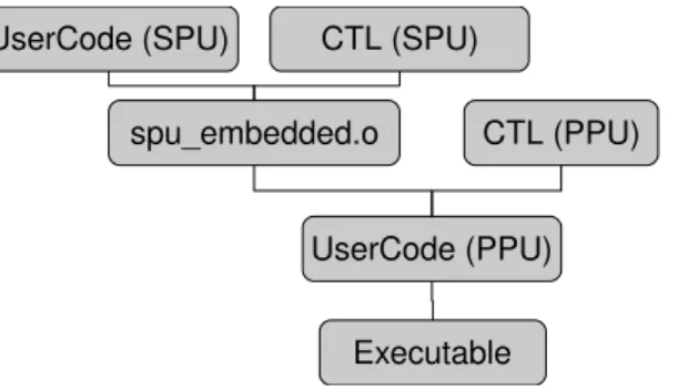
4.1 Declaration of SPE embeddeded code . . . 38
4.2 Composed Structure . . . 40
4.3 SPE control variable and local Transactional log variable . . . 40
4.4 TxStart pseudo-code . . . 41
4.5 TxLoad pseudo-code . . . 41
4.6 TxStore pseudo-code . . . 42
4.7 TxCommit pseudo-code . . . 42
5.1 Transaction 1 — Conflict . . . 44
5.2 Transaction 2 — Conflict . . . 44
5.3 Transaction 1 - Abort . . . 44
5.4 Transaction 1 — Isolation . . . 45
1
Introduction
1.1
Motivation
As the need for high demanding processing in almost every aspect of our society grows, Cell Broadband Engine Architecture (CBEA) was designed to provide a very high performance with low power consumption. Cell Broadband Engine (CBE) appears as a very peculiar type of architecture, leading to the need to develop brand new frameworks, compilers and runtime management tools, therefore implying the need to redesign the application code to achieve the expected performance from such an architecture.
Being an alternative to conventional systems, it is hard to expect from the common pro-grammer the knowledge to code in CBE taking out of the architecture the real potential of it. This represents a massive effort to provide tools to the programmers so that they can abstract from the architecture design. Due to its heterogeneous multiprocessor architecture, concur-rency and parallelism techniques are expected to greatly improve the speedup of the applica-tion code, but they also represent increased difficulty in its implementaapplica-tion, consistency and debugging.
Software Transactional Memory (STM), due to its properties such as being time-line execu-tion independent and providing the concepts of atomicity and isolaexecu-tion, presents an approach to this high-level abstraction tools for the programmer on CBEA. With transactions, the pro-grammer is able to define computations inside the scope of a transaction and benefit from the Transactional Manager to avoid inconsistency in the execution of code and relieves the pro-grammer from the need of explicitly controlling the contention on the objects being accessed in the critical sections.
program-1. INTRODUCTION 1.2. Problem specification mer.
1.2
Problem specification
Most STM engines implement transactional memory for threads executing in the address space of a single computer. Exceptions, such as XSTM [Noe] and the distributed multiversioning STM engine presented by [MMA06], refer to a distributed shared memory system. A STM engine for CBEA does not suit the normal parameters of a simple shared memory system since the sub-processors, the Synergistic Processing Element (see section 2.4.1 for more details), cannot address directly the memory. All data transfers between the sub-processors and shared mem-ory have to be made through Direct Memmem-ory Access (DMA) transfers (see section 2.4.2 for more details). Also, the SPE’s are Single Instruction Multiple Data (SIMD) processors, with distin-guish Instruction Set Architecture (ISA) from the main processor, which arises the need to have special concerns on the specification of a STM framework for the CBE to allow users to take advantage of the massive computational power of these processors.
Also the versatility of the CBEA allows to use it for several different programming paradigms which makes the task of developing and evaluating an STM framework for this architecture complex but also challenging. Providing several distinct synchronization methods, an het-erogeneous multi-processor architecture, a novel memory distribution, a high capacity Bus (Element Interconnector Bus), the distinct compilers, frameworks and open-source libraries available the possibilities are almost infinite.
1.3
Thesis statement and contributions
With this study we intend to show that Transactional Memory paradigm fits CBEA.
The expected contribution is the specification and development of a STM engine for CBE under Linux operating system that allows integration with different programming models. We use Consistent Transaction Layer [Cun07] (also known as CTL) as a basis, due to its feature richness and the good performance achieved on x86 architecture. The integration of CTL on CBEA has several modifications, respecting to the different architecture design, supporting the heterogeneous multiprocessor architecture, its different instruction set architecture (ISA) and taking advantage of the unique memory layout and high memory bandwidth available.
The prototype implements a STM engine for CBEA, and it is benchmarked and tested to certify its correctness execution and performance achieved. We expect to contribute to the sci-entific community with the development of this prototype, providing detailed documentation and presenting the results achieved.
1.4
Document layout
This document is divided in 6 chapters.
1. INTRODUCTION 1.4. Document layout
• Chapter one introduces the problem, discusses the motivation and presents a brief
solu-tion layout.
• In chapter two we present related work. We describe the actual state with STM
program-ming model, with an introduction to Transactional Memory properties and features, fol-lowed by a description of CTL. Also in chapter two, the Cell Broadband Engine and its functionalities are discussed, as well as CBEA and x86 ISA relevant differences.
• Chapter three presents the architecture solution for the specific problem, discussing the
pros/cons of design choices on the provided solution.
• Chapter four discusses the implementation issues of the framework.
• In chapter five the validation and benchmarking of the prototype are presented. Also the
results are discussed.
• Chapter six draws last conclusions on the development of this dissertation and discusses
2
Related Work
2.1
Introduction
In this chapter it is introduced the state of the technologies used in the study of this Disser-tation. The first section introduces Software Transactional Memory (STM) and its properties. Afterwards Consistent Transaction Layer (CTL), a STM framework developed for x86 proces-sor, is introduced and its properties explained since we use this framework as a basis for our prototype.
The following section explains the Cell Broadband Engine Architecture (CBEA), the design, properties and communication mechanisms that the architecture provides. Afterwards a com-parison between x86 processor and Cell Broadband Engine Instruction Set Architecture (ISA) is made in order to understand the distinctions between them. The following section introduces Software Managed Caches (SMC) since it can greatly improve the performance of our solution in the specific architecture (CBEA). The last section introduces STM benchmarks, the specific problems in benchmarking STM application and some of the solutions and models provided in the scientific community in order to effectively and accurately benchmark STM implemen-tations.
2.2
Software Transactional Memory
2. RELATEDWORK 2.2. Software Transactional Memory a limit in performance, it is not feasible anymore to increase the clock frequency, if we consider performance per energy consumed, and this evolution leads us to the present state, where ap-plications and systems are not prepared for this multi-core or multi-processor architectures. Providing tools that help to exploit concurrency and parallelism has revealed to be a very de-manding task [LR06].
Writing concurrent programs is not trivial [Han77], and is mostly based on explicit lock-ing of critical sections where concurrent data accesses may occur and it is always implemen-tation dependent. Transactional memory was proposed as a new abstraction for program-ming [Lom77], providing a high level abstraction for concurrency control in a multi-threaded or multi-processor environment. Being able to consider several pieces of code as transactions and executing them concurrently as if they were being executed sequentially brings notorious benefits.
Transactional Memory (TM) shifts the burden of synchronizing and coordinating parallel computation from the programmer to the TM framework, and the performance results are fre-quently equivalent or closed to fine grain lock based implementations. Although transactions are not the only way to control parallel computation (we still have locks, semaphores, mutexes and monitors) the higher-level abstraction sure makes transactional memory very appellative. This idea came from Lomet [Lom77] in 1977, who did not present any practical implementa-tion until Herlihy and Moss proposed a hardware supported transacimplementa-tional memory [HEM93] in 1993. The term STM was first introduced by Shavit, and Touitou in 1995 [ST95] and described the first software implementation of a transactional memory.
In the sub-sequent sections it will be introduced the transactional model properties and design approaches for software transactional model, specifying the advantages and disadvan-tages of the different possibilities.
2.2.1 Transactional Model Properties
ACID properties
Transactions use the ACID(Atomicity, Consistency, Isolation and Durability) properties as fun-damentals.
• Atomicity— This property states that either all the transaction instructions return
suc-cessful, and therefore the transaction commits successfully, or if one of the instructions fail, the whole transaction aborts and none will be executed.
• Consistency— Consistency is directed related to data, specifically to data handled by a
transaction. It is important that a transaction leaves a consistent data when it ends (either an abort or a commit). Every transaction expects reading a consistent state.
• Isolation — This specific property is very important for parallel environments. Each
transaction has to run correctly even with other transaction executing concurrently, not affecting its data. Frequently it is assumed that the result of two concurrent transactions must be the same as if they were executed serially.
2. RELATEDWORK 2.2. Software Transactional Memory
• Durability— After a transaction commits, the changes have to be persistent, even in case
of system crash.
Usually transactions are closely related with databases, which are context specific, they interact with I/O devices and deal with persistent writes, where the propertyDurabilityis very important to assure persistent memory correctness. In STM,Durabilityis not taken into account, since we are dealing with memory writes/reads and data in memory is usually transient.
Transactions States
In the programmer perspective, there are three possible outcomes for a transaction. A trans-action might commit; abort; or run in a undefined state [SKS05]. A transtrans-action commits when all the instructions of the transaction have been successful. It aborts when any of the instruc-tions fails. It might be undefined if it neither aborts or commits which results in a undefined or unhandled error on the execution of the transaction.
From the point of view of the system the transaction might beactive, partially committed,
committed, failed or aborted. An active transaction refers to a running transaction. In case of instructions completion (those inside the scope of a transaction) the transaction will try to com-mit, it is consideredpartially committed. If all changes were successful then the transaction is consideredcommittedIn case of any failure, the transaction must rollback, therefore encounter-ing itself in a failed state, which is succeeded by the Aborted state, referrencounter-ing to the completion of the rollback leaving the data consistent.
Basic Constructs
An atomic block represents the blocks of code that will be executed as transactions. An example of this can be seen below.
Listing 2.1: Atomic Blocks
1 int calculate_square_area(int x, int y){ 2 atomic{
3 int z = multiply(x,y);
4 }
5 }
All the operations inside an atomic block have theIsolationandAtomicityproperties assured and any function called inside an atomic block inherit the same properties.
Nested transactions
2. RELATEDWORK 2.2. Software Transactional Memory outer transaction should abort or not. Nested transactions were introduced by Moss [Mos81]. There are three types of Nested Transactions:
• Flattened Nesting— Flattened transactions behave, as the name says, as if the inner
trans-action expanded into the outer transtrans-action. Aborting the inner transtrans-action makes the outer transaction to abort as well and committing the inner transaction has no effect un-til the outer transaction commits. Data from a inner transaction is visible to the outer transaction, but not to the other transactions. These are easy to implement but a very simplistic way to approach nesting, but they can be used in a high rate commit scenario, where performance is critical.
• Open Nesting— Open nesting most specific attribute is that the result of the changes made
by a inner transaction is made visible, not only to the outer transaction, but also for the rest of the system. Notice that even if the outer transaction aborts, the results altered by the previously committed inner transaction are still visible.
• Closed Nesting— Closed transactions aborts without aborting the outer transaction. When
it commits passes control to the outer transactions, and changes made by the inner trans-action become visible to parent transtrans-action, but not to the rest of the transtrans-actions.
Distributed transactions
Distributed transactions happen often in the context of large databases, where data might be replicated through distributed data centers. To maintain certain properties, like atomicity, each agent must coordinate between them. A common approach for this is the Two-Phase Commit protocol. Each transaction acts as an agent, and whenever there is the need to commit a transac-tion the first phase of the protocol begins. The transactransac-tion responsible for the commit, lets say the manager, asks each agent the request to commit. After each agent “approve” the request, which implies that they execute the transaction to the point where they are able to commit, the responsible for the protocol initiation then starts the second phase, which is the effective commit of the changes, and afterwards the release of the locks. If any of the agents does not succeed in any of the phases, it informs the manager, which will message all the agents that the protocol has failed and therefore no changes will be made.
This protocol is widely known and used, but the fact that holds the locks while the protocol is in execution is a drawback since it minimizes concurrency and strongly affects performance.
2.2.2 Design approaches
Concurrency Control and Conflict Detection
Concurrency Control is necessary to synchronize concurrent accesses to an object/data. When dealing with concurrent transactions sooner or later a conflict will happen. By con-flict we mean that at least two transactions are accessing the same data, and one of them is trying to modify the data.
2. RELATEDWORK 2.2. Software Transactional Memory There are three possible states. A conflict occurs, a conflict is detected and a conflict is resolved. An occurrence of a conflict doesn’t mean that it is immediately detected. We consider a conflict resolved when a TM rules/protocol is applied to resolve the conflict.
Resolving a conflict can be made in several ways. It varies on concurrency control mecha-nism of the TM namely if it is a pessimistic or optimistic concurrency control mechamecha-nism. In a pessimistic concurrency control approach, all the three stages happen sequentially. As soon as a conflict happens, it is detected and resolved. In a optimistic concurrency approach the same is not true. Conflict detection and resolution can be delayed.
Conflict Detection can be made at one of these times [LR06].
• Detected on open happens when we try to access the object or data at the first reference
to the object.
• Detected on validation can be made at any time of a transaction execution, and even
sev-eral times. This validation is a routine to validate the data set, checking if it has been modified by any other transaction. The result of this varies depending on the TM imple-mentation.
• Detected on commit validates the data-set before committing, checking if any data has
been modified by other transaction.
Early detection avoids lost computation on a transaction, since it could abort immediately. However there are cases where an early detection aborts the transaction that could have com-mitted otherwise.
Keeping track of object accesses through a list of transactions accessing the object can be difficult to maintain since there are no guarantees of how many transactions will access the data, obligating therefore to an implementation of dynamic structures so that no boundary exceptions occur. This boundary problem may occur with versioning data-sets, since it can as well outbound the max value, but it is a fairly easier problem to overcome.
Several possibilities can happen with conflicts. If a system desires to allow concurrent reads, can even not track the reads like Invisible read TM system [LR06], but any transaction that performed a read on some data-set must validate it before committing.
Scott [Sco06] identified 4 policies for detecting conflicts:
• Lazy invalidation — T1 writes an object. T2 reads the same object and T1 commits before
T2
• Eager Write-Read — T1 writes an object. T2 reads the same object but none of the
trans-actions has committed yet
• Mixed Invalidation — T1 writes an object. T2 reads the same object and then writes into
the same object and none of the transaction has committed yet
• Eager Invalidation — T2 reads an object. T1 writes into the same object and none of the
2. RELATEDWORK 2.2. Software Transactional Memory When a conflict occurs, in a Late Concurrency Control approach, a transaction might be executing in a inconsistent state. This has to be either prevented or corrected.
• The validation method requires validation of the read-set to assure that the data is
con-sistent. Depending if “operating” in deferred-update or direct-update mode, rules have to be made to guarantee the consistency of data.
• Invalidation method invalidates the read-sets of an object/data when that data-set is
ac-cessed by any transaction aiming to modify the same data-set.
• It is still possible to allow inconsistency toleration, since validation might be expensive.
This approach needs to guarantee that none of the other concurrent transactions will execute correctly using any data manipulated by this inconsistent transaction.
Weak and Strong Isolation
There are two types of isolation, weak and strong [BLM05]. When we access data in a trans-action environment, we use a STM engine, therefore we expect the engine to protect our data from concurrent transactions. But what if a non-transactional access is made to the data? Weak isolation allows the data access, therefore expecting the programmer not to access data outside of the transaction environment, or access it in a controlled way, so that it does not corrupt the data.
In closed memory systems such as C where malloc()/free() instructions prevail we have to take in account recyclable data, so that non-transactional instructions might access it.
Strong Isolation states that data is protected from non-transactional access, so it is only possible to access it through the STM engine. Basically it turns every single instruction out of Transactional environment into a transaction, forcing it to respect the transaction engine rules.
Transaction granularity
Transaction Granularity refers to the amount of data that is being controlled by the STM for conflicts. Granularity can differ from system to system, some refer to an object, some for blocks of data or words. These are distinguished by it’s size, therefore implying fine grain or coarse grain. The finer the grain, more concurrency is allowed, the coarser the grain, more simplified approach and less overhead is achieved.
Coarse object granularity is appellative, since we can associate metadata easily to the object, but if we are accessing just a small amount of data in the object, and other transaction tries to access a different data in the object, it won’t be able to.
Blocking vs Non-Blocking synchronization
Early TM systems used nonblocking synchronization, this type of synchronization offers a stronger guarantee of forward progress, while blocking synchronization imposes concurrency limitations.
2. RELATEDWORK 2.2. Software Transactional Memory Ennals [Enn05] suggested that system deadlocks prevention are the only compelling reason to implement non-blocking transactions systems.
TL2 [DSS06] article suggests that experience until now reveal that blocking synchronization STM systems perform better and are easier to implement than non-blocking synchronization systems.
There are mainly three types of forward progress guarantee [LR06]:
• Wait freedom is the strongest guarantee that all threads accessing a common set of objects
make forward progress.
• Lock freedom assures that at least one thread makes forward progress from all the set of
concurrent threads.
• Obstruction freedom is in others words an optimistic concurrency control, since the only
requirement is that a subset of data (partially completed operation) can be rolled back.
Direct and deferred update
Direct and deferred update state how data should be handled when its modified.
Using direct update approach implies that the data is directly updated when it is modified, therefore adding the need to keep a log change, so if the transaction aborts, we are able to rollback all the instructions, leaving a consistent and unchanged state of the data regarding the beginning of the transaction. The data has to stay the same, as if the transaction has never happened.
When deferred update is used, the data is handled locally, through a copy. If the transaction commits successfully, the data then is moved to the proper location. Of course this is not as simple as this description, some considerations have to be taken into account regarding data accessed by other transactions. If no other transaction modified the state of the data, then the effective changes are made into memory. Aborting a transaction in deferred update is as simple as deleting the private copy of the transaction.
The direct update mode speeds up the reads since they simply access shared memory to read, however they maintain locks on variables until transactions commit. On the other hand deferred update minimizes the overall contention by only acquiring the locks on commit time, but the drawback is the necessity to check the write set of current transaction, verifying if any change was made to the variable that we wish to read [Cun07].
Lock Placement
2. RELATEDWORK 2.3. Consistent Transaction Layer (CTL)
2.3
Consistent Transaction Layer (CTL)
2.3.1 Introduction
CTL [Cun07, CLD08] was developed in Universidade Nova de Lisboa by Gonc¸alo Cunha as his Master Thesis and adds some functionalities to Transactional Locking 2 [DSS06], a global ver-sioning clock based STM engine presented bySun Microsystems. Some of the added function-alities are the basis of a STM engine design, others performance related. Besides his objective to improve the STM engine, the objective was that CTL would ran in x86 processor instead of SPARC, and that it would use GCC instead of SUNPRO C compiler.
Transactional Locking 2 (TL2) was chosen due to its singular characteristics. Although it is a lock based implementation, it helds locks for very short periods of time (only on commit time), and it suits open memory programming languages such as C. Also, the global versioning clock presented a new approach towards consistency validation of transaction states. TL2 used a redo logging strategy and allowed lock to be placed on a separate table or adjacent to data, depending on compile time options from part of the user. CTL ended as a prototype with more features than the TL2, that will be described in the following sections.
2.3.2 CTL Features
User abort
CTL provides a way to a user to explicitly abort a transaction. This is very useful in some cases, since it might be needed to abort a transaction, not because of transaction inconsistency but due to logic in program execution.
Automatic transaction retry
Automatic transaction retry happens when two transactions collide, therefore one of them has to abort. If there is no automatic transaction retry the programmer has the need to explicitly test if the transaction committed successfully. With Automatic transaction retry implemented in CTL the transaction automatically retries, corresponding to a exactly one successful commit. This has been achieved withsetjmp/longjmpinstructions. Thesetjmproutine saves the processor state on the beginning of a transaction, whilelongjmprestores the processor state that has been previously saved bysetjmp.
Transaction Nesting
CTL transaction nesting is partially based on Closed Nesting. If the execution of a sub-transaction commits successfully the transaction log is concatenated with the log of the outer transaction. In case where the sub-transaction aborts the log is discarded and the control passes to the par-ent transaction. However when a collision with other transaction is detected even the parpar-ent transaction aborts, since the conflicting variable might as well been read by the parent
2. RELATEDWORK 2.3. Consistent Transaction Layer (CTL) tion. This can be avoided by validating the whole read set of all transactions, assuring that the parent transaction is still in a consistent state.
Update techniques and validation modes
CTL was developed based on TL2, which used thedeferred updatetechnique with aredo logging. CTL not only implements the deferred update mode, as well as direct update mode using a
undo log. These extra features developed in CTL allows the user of CTL to use, according to application necessity, each one of the approaches. With the deferred update technique, none of the changes is made visible to all other transactions until the transaction commits successfully. This is achieved through keeping a temporary copy of the real values (the redo log), combined with the global versioning clock to assure state consistency of the transactions.
The direct update mode approach, results in direct changes of the memory values, keeping an undo log, allowing rollback in case the transaction has to abort leaving therefore the data consistent.
When a transaction starts, it reads the global version clock into a transaction timestamp. When a transaction loads, transaction checks if the variable is already in the write set, if it does mean that it has already been accessed within the transaction and returns the value written in the write-set, otherwise, logs the read in the read-set and returns the value. For the read to be valid, the transaction must check if the lock isn’t held, if the lock version is the same in both checks (before and after the read) and that the lock version is lower or equal to the transac-tion timestamp, guaranteeing that the transactransac-tion is in a consistent state. When a Transactransac-tional Store happens, the transaction logs the write on the write set. When a transaction commits, the corresponding locks are obtained, the read set is validated, the global version clock is incre-mented, the new variable values are copied from the redo log to the corresponding memory positions and finally the locks are released with an updated version corresponding to the new global version clock number. Aborting a transaction is as simple as discarding the redo log (in redo mode).
2.3.3 CTL granularity
2. RELATEDWORK 2.4. Cell Broadband Engine
2.4
Cell Broadband Engine
2.4.1 Overview
CBE began as a challenge to improve the relation between power consumption and perfor-mance to high demanding processing applications. Sony, Toshiba and IBM started a joint ven-ture to design an architecven-ture capable of providing such demanding goal.
To be able to take a look into the Cell advantages and disadvantages it is important to talk about metrics. Several metrics are usually used to prove/test architectural design efficiency, such as performance per cycle or design frequency, but as we move into a world where power is more expensive and specially limited, we have to take into consideration the power efficiency of our systems. Several metrics can be used to measure this efficiency, such as energy per operation or performance per transistor. In the design of CBEA these kind of metrics were taken in consideration.
Most architectures now-a-days do not take into consideration the power/performance ra-tio, and some architectural choices like virtual memory, caches, out-of-order executions and hardware branch predictors decrease this ratio substantially [Pet05], so in CBE, some sacrifices were made in order to improve this ratio. Most of the disadvantages resulting of these “sacri-fices” go to the programmer, that have to take some issues in consideration on the development of applications.
Cell Architecture Design
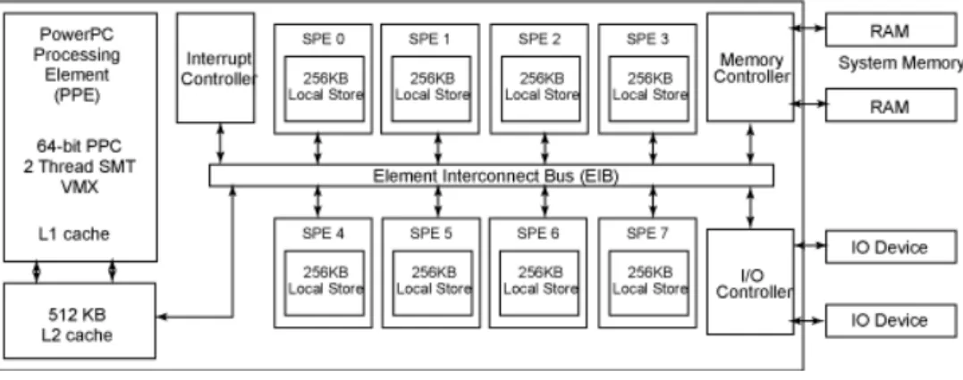
CBEA was finally designed as shown in figure 2.1 and it is composed by a main processor(PPE), eight cores (SPE), an interconnection bus (EIB) and system memory.
Figure 2.1: General Architecture Design of CBEA.
The CBE has a heterogeneous multi-core processor configuration, pursuing the objective of taking advantage of the parallelism techniques, residing its computational power on the SPEs units. This choice of heterogeneous multi-core architecture was made due to the fact that the architecture would have to handle heavy computation (and therefore the SIMD dataflow of
2. RELATEDWORK 2.4. Cell Broadband Engine SPEs are a good choice) and manage an Operating System (OS), that have very frequent context switches.
The Power/Performance ratio was roughly taken in consideration and several choices were made in order to improve this ratio. For instance, the PPE and the SPEs do not support out-of order execution, neither have branch predictors by hardware. These choices reduce the price and power consumption of Cell.
Power Processing Element
The Power Processing Element (PPE) is the responsible for the management of the system. It controls all the 8 cores (SPEs).
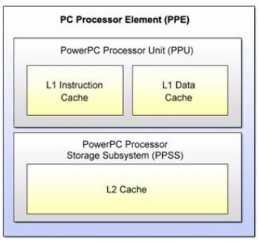
The PPE is a 64 bit PowerPC 970, running at 3.2GHz, 2-way simultaneous multithreading processor. It consists of a Power Processing Unit (PPU), and a 512KB 8-way set associative write-back cache, used for both instructions and data as shown in figure 2.2(extracted fromCell Broadband Engine Handbook. [IBM07a]) .
Figure 2.2: Power Processing Element General Overview.
Notice that although it is a PowerPC 970 based processor, and it uses its instruction set, its design is much more simpler in order to lower the cost of the hardware. The fact that it uses the same instruction set allows the programmers to start with software based on traditional PowerPC architecture, improving afterwards the software for the CBEA.
The PPU has a 32KB 2-way set associative reload-on-error instruction cache and a 32KB 4-way set associative write-through data cache.
Synergistic Processing Element
2. RELATEDWORK 2.4. Cell Broadband Engine
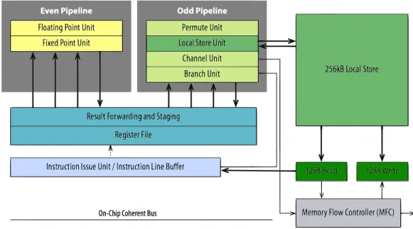
Figure 2.3: Synergistic Processing Element
of unified memory for both data and instructions. The only way to move data to and from LS is through the MFC, which is responsible for all data transfer capabilities of the SPE.
The SPE uses a three level memory organization, (Registers, Local Store and System Mem-ory), that breaks from conventional architectures. This three level organization, combined with asynchronous DMA transfers explicitly parallelizes both computation and data transfers. With this approach, it is possible to minimize the latency on accessing system memory on conven-tional systems.
In figure 2.3 (extracted from SCOP3: A Rough Guide to Scientific Computing On the PlaySta-tion 3) we can take a deeper look at the SPE. We can see the interaction between LS and MFC for data transfer, as well as the two SPU pipelines, the odd pipeline and the even pipeline. The odd pipeline is responsible for memory operations, while the even pipeline is responsible for the computation. This pipelining allows us to perform two SIMD instructions per cycle, one compute instruction and one memory operation.
2.4.2 Memory and Communication
Memory in CBE
Memory in CELL, due to its heterogeneous multiprocessor architectural design, is decentral-ized. This introduces a very sensitive area of CELL since taking good advantage of the archi-tecture depends on the effective usage of the memory.
The way the PPE and the SPEs access main memory differ substantially. To access the main memory, the PPE accesses main storage with load and store instructions, to or from a private register file. The SPE’s on other hand must move data from main memory to its Local Store
2. RELATEDWORK 2.4. Cell Broadband Engine (LS) before the SPU can fetch instructions.
Since the SPE’s can only execute code inside its LS, data has to be moved into it from main memory and then moved back to main memory. This is possible by using DMA transfers. This data-flow from SPE’s LS and main memory is intermediated by two interface controllers, the MIC (Memory interface controller) connected to the system memory and the MFC (Memory Flow Controller), in which the DMA engine is integrated. The MFC allows the SPE to pipeline the data while working on current computation, therefore providing a very powerful combi-nation for non-locking computation. These two interfaces provide several mechanisms to the programmer to manage memory and synchronization.
The Memory Flow Controller provides to the SPE data transfer and synchronization capa-bilities. It implements the interface between SPU and EIB, LS and system memory. Notice that any data transfer can be initiated by either the SPU or SPE.
The Cell BE memory and DMA architecture are fairly flexible. The PPE provides to the MFC some resources, such as MMIO registers, with effective-address alias on main storage, so others SPEs or the PPE can access and control the SPU. The local stores of the SPEs are mapped into the global address space. The PPE can access (through DMA) local stores on the SPEs, and can set access rights. The SPEs can initiate DMA to any global address, including the local stores of other SPEs.
Communication
There are three possible ways of communication in CBE. Through DMA transfers, signals or mailboxes. The most important one is obviously DMA transfers specially due to its non-blocking facility.
DMA are non-blocking transfers, which allows to pipeline the data while computing the data. DMA can be issued from PPE to SPE, from SPE to PPE and from SPE to SPE. DMA messages are not ordered and they have a maximum size of 16KB, but it is always possible to combine multiple DMA transfers to move data bigger than 16KB. DMA lists are perfect for this, and they can combine up to 2048 DMA transfers. Each SPE is capable of queuing 16 requests. Also there is a proxy queue, that the PPE and other SPEs are able to access. This proxy queue can queue 8 requests. These lists are made available by the DMA engine in each MFC.
Signals are 32bit registers in SPU. Each SPU have two signal-notification channels. They are a very trivial way of communication, it can be used to signal the completion of a task. Each register has a corresponding MMIO register on which the data is written by the sending processor. Each SPE can only access his own registers, therefore if any other SPE, or even the PPE, has the need to access the information, it can be done by accessing the respective MMIO register. Any read made by the SPE on its own registers will clear atomically the channel, contrary to any MMIO read, that wont clear the channel.
2. RELATEDWORK 2.4. Cell Broadband Engine counters available to verify the state of the queue. Still, they provide a good way to message another SPEs. Mailboxes are 32-bit messages, and they have a FIFO queue. Each SPE have a four-entry inbound mailbox and a two one-entry outbound mailbox. Mailboxes are not a good way to acknowledge transference completion because SPE knowledge of DMA transfer completion is that the local buffer is ready for reuse, so there is a possibility that the mailbox will be read by the PPE but the data isn’t there yet. Also, obligating the PPE to continuously check the outbound mailbox of the SPE might flood the bus.
Barriers and Fences are mechanisms to order DMA messages within the queue or tag group. Issuing a barrier will order it with respect to messages issued before and after the current mes-sage. A fence will only order it to respect of the previous messages. Although these mecha-nisms are very useful, it is recommended to use them as less as possible since it wont allow the arbiter to improve the performance of the DMA transfers.
2.4.3 Programming Models
This section exploits the programming models for CBEA. Achieving the best performance on any architecture depends on the exploitation of its specifications. In CBEA we can define two main models, PPE-centric, and SPE-centric.
As CBE attracts several different sectors of computer science community, there are several programming models that fit well in this architecture [BLKD07].
Function-Offload Model
Also called Remote Procedure Call Model, this model is PPE-centric. The PPE manages the ap-plication, and offloads the computation to the SPEs. It is the most basic approach to the CBEA. After identifying the code to be run on the SPE, a remote procedure is called through a stub, hiding the communication issues to the programmer. This stub will manage the procedure and communication both ways.
Computation-Acceleration Model
This model is SPE-centric. It uses the PPE almost only as a system service or a controller. This model relies on the SPE for high computation, so it is more adequate for computational demanding tasks.
It can use shared memory among the SPEs or a message-passing model for data bulk move-ments. The workload can be partitioned either by the programmer or the compiler. Shared and distributed techniques are used in this programming model.
Streaming Model
The streaming model treats the SPEs as pipelines, where each SPE is responsible for a different task (not necessarily though) on the data. The pipelining can be serial or parallel, being possible
2. RELATEDWORK 2.5. x86 vs Cell Broadband Engine instruction set architecture to achieve better results in a two data streams model than in a one data stream model as stated in [JGMR07].
This approach is suited for computation demanding tasks and also for the tasks that have the need for big transfers of data, since the internal bandwidth available between the SPEs is from far much bigger than system storage. But notice that it is important that the workload can be divided in equal parts, otherwise, there is no sense in having an SPE with a huge workload and another idling. In this model the PPE simply acts as a stream controller.
Shared-Memory Multiprocessor Model
The CBE can be used as a shared-memory model. With DMA cache coherency we can imple-ment this model by DMA commands, from LS to the shared memory and vice-versa. The PPE and SPE have all the same address space in memory. This is only possible because of the global addressing schema of the CBE. DMA also provides lock-line commands, which allows us to make atomic update primitives.
Asymmetric-Thread Model
The Asymmetric-Thread Model is very widespread on SMP. In CBE this Model is possible, and is even implemented by theSPU Runtime Management Library SDK, but the preemptive context-switching in the SPEs impose some overhead and costs, since SPEs support it more for debugging purposes.
User-Mode Thread Model
The User-Mode thread is a model where a thread is run by an SPE, which managesmicrothreads
oruser-threads. The SPE thread is supported by the Operating System, but themicrothreadsare supported by user-software without the interference of the OS.
It is possible for the microthreads to be ran in different SPEs. The SPU schedules task in shared memory, that can be processed by any SPU available.
This model has the advantage that has a predictable overhead, since it is running on a set of SPUs, managed by a SPE.
2.5
x86 vs Cell Broadband Engine instruction set architecture
Instruction Set Architecture (ISA) is the boundary between software and hardware. In other words it allows privileged software to manage the hardware. The ISA defines the instruction set (range of instructions available), datatypes available, the addressing modes(define how to calculate the effective memory address of an operand by using information held in registers) and the instruction formats.
2. RELATEDWORK 2.5. x86 vs Cell Broadband Engine instruction set architecture There are several types of addressing modes, they specify how to reach the operands. The instructions addresses specify how to calculate the effective memory address of an operand by using information held in registers. There are several different types of addressing modes like
Register DirectorRegister Indirect. The first define the value of operand directly in the register, the former define the address of the operand in the register.
2.5.1 x86
The x86 architecture is a variable instruction length, primarily two-address CISC design with emphasis on backward compatibility. x86 allows non-aligned data, but it is not advisable to do so, due to performance issues. The x86 provide 8General Purpose Registers(GPRs), six segment registers, one flags register and an instruction pointer. x86 is little-endian meaning that multi-byte values are written least significant multi-byte first.
x86 supports 32bit 16bit and 8bit datatypes, single and double precision IEEE floating point. The operand types in x86 can be passed mainly in 3 ways, directly in the instruction, it can be stored in register and it can be in memory. Obviously if the operand is stored in memory a bus access has to be made, therefore making the execution slower. The reduced number of GPRs has made register-relative addressing (using small immediate offsets) an important method of accessing operands.
Several extensions to the ISA have been added to x86, like MMX and Streaming SIMD Extension (SSE) which allow SIMD instructions and advanced math operations.
2.5.2 CBEA
Cell Broadband Engine is as we know a heterogeneous multiprocessor architecture intended to support a wide variety of needs. As SPEs are designed for computationally intensive tasks and therefore SIMD processors, their Instruction Set differ from the PPE, actually being very close to the PPE’s Vector/SIMD Multimedia Extension (VMX or AltiVec). This means that we have two different instruction sets in CBEA. The instruction set for the PPE, which is an extended version of the PowerPC instruction set, and the SPU ISA.
Power Processing Element and PowerPC
The PPE instruction set is based in the PowerPC 2.0.2 ISA and has some enhancements. This enhancements are the VMX, that add 128 bit datatypes for vector and scalar operations, some new instructions and C/C++Intrinsicsfor VMX. Intrinsicsare C language commands, in the form of function calls, that can substitute one or more in-line assembly-language instructions. The CBE programming handbook [IBM07b] gives a general view of the PPE ISA but detailed descriptions can be found in thePowerPC user Instruction Set Architecture[WSMF03] manual. CBE provide 32 General Purpose Registers (GPRs) [IBM07c].
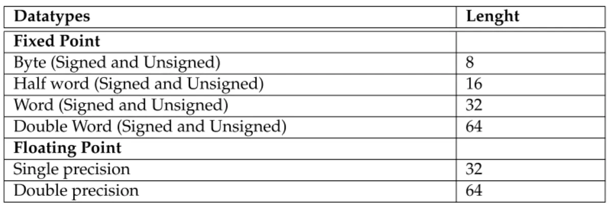
The data types supported by the PPE can be viewed in table 2.1.
In CBE when a instruction is presented to the processor, the two most low-order bytes are ignored. The addresses point to theMost Significant Byte(MSB) since CBE uses the big-endian
2. RELATEDWORK 2.5. x86 vs Cell Broadband Engine instruction set architecture
Table 2.1: PPE supported datatypes
Datatypes Lenght
Fixed Point
Byte (Signed and Unsigned) 8
Half word (Signed and Unsigned) 16
Word (Signed and Unsigned) 32
Double Word (Signed and Unsigned) 64
Floating Point
Single precision 32
Double precision 64
convention.
The load and store addressing modes always define a base index and there are three differ-ent possibilities:
1. Register- Load or store the contents ofRegister
2. Register + Register- Indexed form of the Load and Store instruction form the sum of the contents ofRegisterplus the contents of base register.
3. Register + Displacement- Forms the sum of Register and a 16bit signed-extended immedi-ate field of instruction and sums the content of base register.
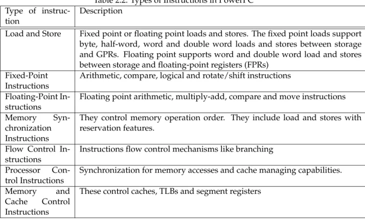
Instructions in PowerPC are 4 bytes long and aligned on word (4-bytes) boundary. It can have up to three operands, most of them specify a 2 source operands and one destination operand. In table 2.2 we can see those instructions. Below we introduce the instruction types available for PowerPC.
Synergistic Processing Unit
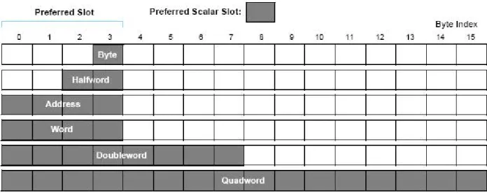
The SPU ISA provides 7-bit register operand specifiers to directly address 128 registers using a SIMD computation approach for both scalar and vector data. The SPU ISA operates on SIMD vector operands, with support for some scalar operands. Any scalar operand must be issued within the preferred slot, that are the left-most bytes in the registers (the 4 first bytes). Notice that SPU is a Load/Store architecture, which means it can only access data to move it to the registers, in other words, it cannot operate in LS.
The datatypes supported by the SPU are: byte, halfword, word, double word and quad-word as shown in the figure 2.4 (extracted fromCell Broadband Engine Programmer Handbook).
The instructions in SPU have to take in consideration the existence of two pipelines. This allows two up to two instructions per cycle. The pipeline destination depends on the type of instruction issued.
2. RELATEDWORK 2.5. x86 vs Cell Broadband Engine instruction set architecture
Table 2.2: Types of Instructions in PowerPC Type of
instruc-tion
Description
Load and Store Fixed point or floating point loads and stores. The fixed point loads support byte, half-word, word and double word loads and stores between storage and GPRs. Floating point supports word and double word load and stores between storage and floating-point registers (FPRs)
Fixed-Point Instructions
Arithmetic, compare, logical and rotate/shift instructions
Floating-Point In-structions
Floating point arithmetic, multiply-add, compare and move instructions
Memory
Syn-chronization Instructions
They control memory operation order. They include load and stores with reservation features.
Flow Control In-structions
Instructions flow control mechanisms like branching
Processor Con-trol Instructions
Synchronization for memory accesses and cache managing capabilities.
Memory and
Cache Control Instructions
These control caches, TLBs and segment registers
instructions without directly managing the registers. It is also in the interest of the programmer to use this extensions since the compilers that supports them will produce efficient code for SPEs. Intrinsics allows the user to make not only dataLoad and Storesand instruction scheduling but much more.
Intrinsics are divided into three sub-areas. Specific intrinsicsare the functions that are mapped one-to-one with assembly in-line instructions. Generic Intrinsicsare the functions that include more than one assembly in-line instruction. Composite Intrinsics are the most complex type, they can be considered as a list ofGeneric Intrinsics.
Since the LS is single-ported (can only access one address per cycle) and it is a unified memory for both instructions and data, it might happen instruction starvation, since DMA transfers have priority over instructions fetches. To try to avoid this, it is useful to transfer as much data as possible in one chunk, for both DMA transfers and instruction fetches. The LS allows 32 instruction fetch loads per requests.
2. RELATEDWORK 2.6. Software Managed Cache
Figure 2.4: SPU registers, data types and preferred slot.
2.6
Software Managed Cache
Caches are storage mechanisms that duplicate data in order to increase performance, that oth-erwise would have to access some higher latency cost memory/storage. Widely known in form of hardware caches on modern CPU’s, they store data in small hardware mechanisms part of CPU in order to improve performance and reduce accesses to system memory. The concerns in caches has always been managing inconsistency on several private copies, since data structures or variables are replicated through the caches. Therefore this inconsistency has to be controlled, either by software schemes or hardware schemes. Caches are used on systems to improve the performance of irregular pattern in memory accesses since they have a good probability of a given data is already present “locally“ instead of having the necessity of accessing system memory. This happens by exploiting several techniques like the spatial locality of memory accesses.
DMA transfers can be of high cost depending on the granularity of the data being trans-ferred. One way to improve this is to make DMA transfers as big as possible in order to reduce the overhead. In the approach where user fetches data from main memory ”on-demand”, that is, as the data is being requested, it might happen that the buffer (EIB) will be filled very quickly, reducing performance.
For the reasons stated above a private software-managed cache can be used in SPE’s LS in order to improve performance. Specially regarding the write-set, since each load in the scope of a transaction must verify the write-set for previous changes on that address. Since we will be flushing the write-set into main memory, due to memory limitations of the LS, the latency will increase upon aTxLoad()command, therefore, using a cache for the write-set will hopefully reduce the latency on accessing the write-set.
2. RELATEDWORK 2.6. Software Managed Cache hit-ratio of data on LS and reduce the overhead of DMA transfers, since transfers will fetch not only the specific data but also the surroundings.
CBEA provides a software managed cache as an API for usage on the SPEs. This software managed cachecombined with the STM framework can provide a powerful tool towards perfor-mance and efficiency.
3
Architecture solution
3.1
Introduction
Transactions allows to execute pieces of code atomically, which results in either all the opera-tions inside the scope of the transaction being executed return successfully or none will. Most modern processors architectures are evolving to core. To really take advantage of multi-core or multi-processor architectures it is necessary to rethink the whole applications in order to take advantage of the parallel programming techniques. Therefore STM has been gaining pop-ularity and importance by taking advantage of this multi-core architecture effectively instead of simply dividing threads into each processor core.
In such architectures, like CBEA, it is expected that concurrency and parallelism techniques improve performance substantially, however the high performance solutions presented for CBEA are very specific due to its novel architecture and memory distribution and it is still hard to develop tools that are able to provide an abstraction layer to the programmer that is able to exploit concurrency and manage consistency. Software Transactional Memory is a pro-gramming model that proposes this abstraction layer, and is gaining increased popularity and several prototypes have been developed with performance close to fine-grain specific imple-mentations for the domain problem. The possibility of using STM to develop a tool capable of hiding all the memory management and consistency in CBEA is very appellative. In this chap-ter we propose to specify a STM engine to CBEA and discuss the advantages and disadvantages of different STM approaches on implementing such engine.
3. ARCHITECTURE SOLUTION 3.2. Challenges want to use the whole set of processors available (PPE plus SPEs), since SPEs are not able to di-rectly access system memory. This introduces the challenge of effectively using the three level (registers, local store and system memory) SPEs memory that breaks from conventional archi-tectures. The usage of a previous STM framework as a basis, Consistent Transactional Layer (CTL), is made due to its feature richness and good performance achieved, namely the redo and undo log modes and automatic transaction retry in case of failure.
3.2
Challenges
In an architecture where the sub-processors do not allow direct addressing of system mem-ory, instead using DMA transfers for data transfer among main and local memories, imposes higher concerns when developing a simple program. This happens because the data that is being moved between the main memory and the sub-processors have no integrity check, being possible that different copies of the same data are manipulated concurrently, therefore delegat-ing the concern of integrity check to the programmer of the application.
We will now discuss the overall problems in programming in such peculiar architecture. This represent general issues. Afterwards the specific problems that an implementation of a STM framework might bring are approached.
In CBEA, the LS’s size limitation of 256KB for both code and data is really the main concern. This can be fulfilled very quickly and some techniques like code overlay [IBM07d] are used in order to overcome the problem for the code size problem. For the data bulk movement problem the correct management from the programmer is expected in order not to exceed the size allowed.
Mailboxes are 32 bit messages and are used as communication mechanisms between PPE and SPES and also between SPES. As they can be a good mechanism of communication they may also impose stalling of the processor, since reading an empty mailbox will stall until an entry is detected. The same happens when writing into a full mailbox. This might even be the expected behavior of the program, since execution may be unfeasible until the expected message arrives. But this stalling behavior in a non-deterministic execution flow of concurrent threads might be a problem.
So when it comes to develop a STM framework capable of using SPE’s in a transactional environment its possible to identify some problems.
1. No matter we are working in deferred update mode or direct update mode, a log has to be kept for each transactional read or write. This mechanism, combined with the low space available on SPE, imposes even more space problems. The STM future user, which is unaware of the details of the implementation will face even less memory available if we choose to follow the natural solution of keeping the logs locally in LS. These might grow very fast, and that will depend on the specific program using the STM.
2. When working in an SPE perspective, we imagine we need to make a change, actually a very sensitive change in some remote memory location (main memory). In these cases
3. ARCHITECTURE SOLUTION 3.3. Solution Layout an atomic CAS is most of the times made (in form of inline gcc asm), in order to prevent any preemption from the cpu. Atomic functionality through DMA can be made from the SPE side to main memory, making a correspondence to the lwarx andstwcx (processor atomic instructions) PPE operations. Still this represents a higher latency if we wish to implement a routine which has several steps of verification (Lock acquisition, effective changes on memory positions and completion of validation).
3. DMA transfers must be aligned to boundaries. Maximum efficiency is reached when memory is aligned to 128 bits, being possible to transfer 1, 2, 4, 8 and multiples of 16 bytes. So it is not possible to transfer a structure that has 6 bytes, unless we divide it in two distinct transfers or we pad the structure to one of the possible transfer sizes. This concerns the development of the STM framework but also the user that must take this in consideration when coding for CBEA.
3.3
Solution Layout
The CBE, considering it is a Heterogeneous multi-processor architecture with local store for each SPE, intuitively fits well in aTransactional Memoryframework working in deferred update mode, since we would compute all instructions on the SPE’s and we would only need to vali-date the read/write-set on commit time reducing overheads on accessing main memory. This goes toward a function off-load model, where we offload task to SPE’s to be executed. The costs from working on direct-update mode would grow, since we would increase latency on accessing main memory for each write to a variable, therefore this approach is at first sight undesirable. Minimizing accesses to main memory equals minimizing latency resulting in an increased performance.
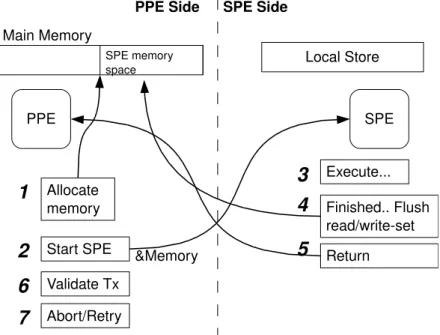
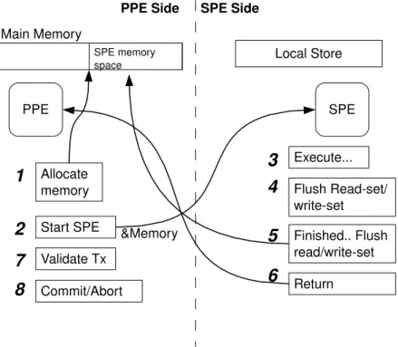
The proposal is to use a shared-memory model, where transactions are executed in the SPEs and the PPE simply acts as a manager and transaction validator. Although transactions are allowed in the Power Processing Element (PPE) the focus will be on developing the support for transactions in the SPE’s due to their high processing capacity.
In this approach the SPE fetches data necessary to its own LS (on demand), computing the code and changes are only made visible upon commit, meaning we will be working in a deferred update mode. This represents developing a library to the SPU that will allow the pro-grammer to start a transaction within SPE context, load a variable, either from main memory or local store, store a value and commit a transaction. On the other side, the PPE, we will have also a library (an extended CTL) which will be able to validate the transaction.
3.3.1 Design Choices
As stated above, a deferred updateSTM frameworkseems to fit better in this particular archi-tecture than a direct updateSTM framework.
3. ARCHITECTURE SOLUTION 3.3. Solution Layout 1. As a first model approach (Fully Local Model) a simple framework is capable of execut-ing transactions in SPE environment. This straightforward approach intends to present a functional way to execute transactions without any special performance improvement nor memory size concerns. This model has a limitation which is the memory. In this model the programmer has to be aware that it might happen that a very big transac-tion might out limit the memory space allowed in the LS. This is because of the write-set and read-write-set having a fixed size in LS (SPE) and that the log is never flushed into main-memory. This model suits for transactions with low workload and low data bulk movement which will never overpass the LS max size. Although this approach has clear disadvantages concerning memory it has also advantages, since the memory is always present in LS reducing overhead on memory communication to main memory. So if it is guaranteed by the user that the transaction will never exceed LS size it might even be a better approach than the following model. This will be further discussed in Section 3.5. An interesting approach that would complement this one would be to make an inter-mediate step between first and second model where the read-set is flushed but not the write-set, this would still translate in high performance and it would free some space.
2. The second model (Multi-buffered Model) aims at solving the memory limitation on LS. In this model a multi-buffered approach is implemented in order to flush the local log into main memory. Therefore this model overpasses the memory limitation by using buffers to keep the transaction log. This way whenever one buffer is full, that buffer is swapped with an empty one and the log is flushed into main-memory in order to free more space for the user. With this approach the user will be able to execute big workload transactions. In this model theRead Logcan be flushed into main memory without any further concern, but the same does not happen with theWrite Log. According to our model the transaction log is dispatched to main-memory introducing a problem. Whenever a transaction issues a TxStore, which is writing into a variable, it is necessary to verify if that memory position has been written previously in the current transaction scope. Therefore any TxStore that does not find an entry in local memory, for the specific address being written, can not assume that it does not exist, it must verify main memory to check for the log entry. This is made by searching remotely in the main memory for the given address and returning a value.
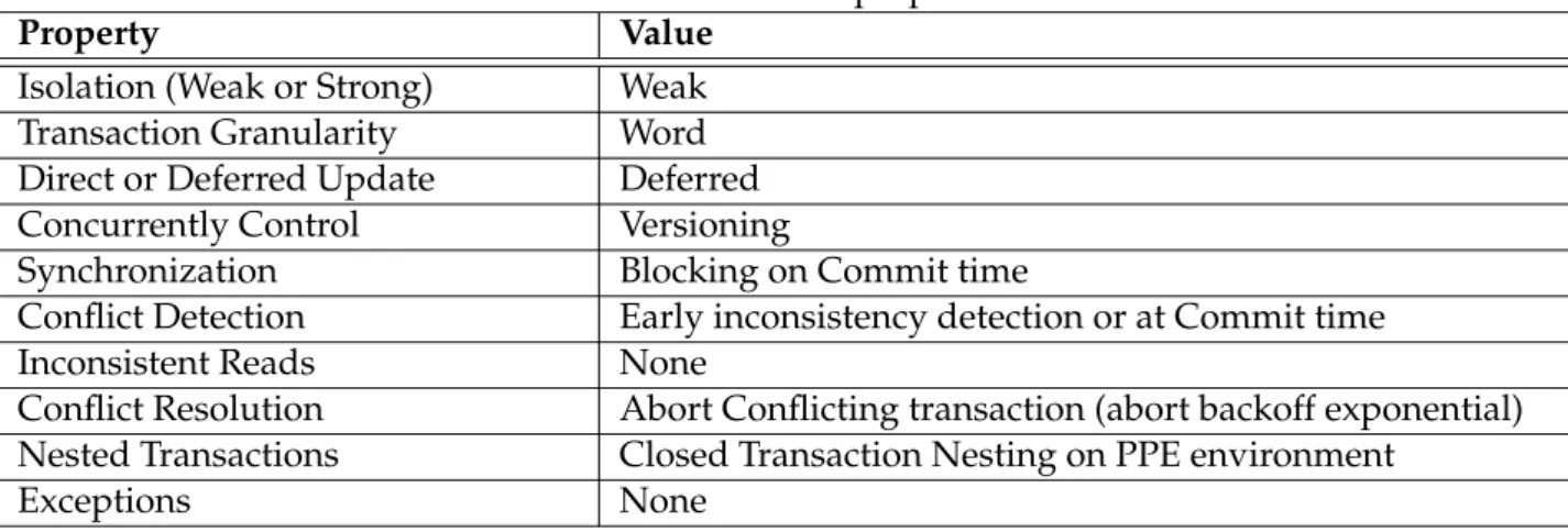
In table 3.1 we can see the properties of the Model. Our Model provides a weak isolation since we allow non-transactional accesses in transactional scope. We use word granularity in our framework working in deferred update. The synchronization method is blocking on commit time, since in order to effectively issue changes in memory we need to assure no other transaction will corrupt the data, therefore using a blocking mechanism to protect the data-set from unwanted changes. Also we provide an early inconsistency detection mechanism in our algorithm. Regarding transaction nesting, it is only supported in PPE transaction scope.