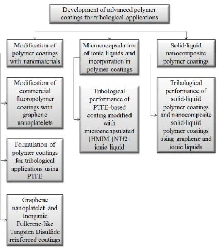
FOR TRIBOLOGICAL APPLICATIONS
Pedro Miguel Vieira Pinto Bandeira
This dissertation is submitted to the Faculty of Engineering, University of Porto, for the degree of Doctor of Philosophy in Chemical and Biological Engineering.
Supervisors:
Prof. Dr. Fernão Domingos de Montenegro Baptista Malheiro de Magalhães Prof. Dr. Adélio Miguel Magalhães Mendes
This work was financially supported by: Flupol – Surface Engineering S.A., and Project POCI-01-0145-FEDER-006939 (Laboratory for Process Engineering, Environment, Biotechnology and Energy – LEPABE funded by FEDER funds through COMPETE2020 - Programa Operacional Competitividade e Internacionalização (POCI) – and by national funds through FCT - Fundação para a Ciência e a Tecnologia.
“Obstacles are those frightful things you see when you take your eyes off your goal.” Henry Ford
A
CKNOWLEDGEMENTS
I would like to acknowledge the support from Flupol, S.A. for funding this work and also for the demonstrated flexibility that allowed it to advance. I present my most sincere thanks to all the persons from the shop-floor to the management for all the support and availability, especially to Rui Gomes, Fernando Leite, Cassilda Tavares and Judith Monteiro.
My most sincere gratitude is also expressed to my supervisors Professor Fernão D. Magalhães and Professor Adélio Mendes for their unrestricted support and understanding, also with regard to my condition as an active company employee with limited available time.
A special mention of gratitude must be addressed to Professor António Monteiro Baptista for all the unconditional support and understanding related to the tribological part of this work.
I would like to thank all my colleagues at LEPABE and CETRIB for the demonstrated support, especially to Artur Pinto and Rui Cruz for all the collaboration.
A word of appreciation must also be addressed to ARCP for the support and for providing some of the necessary resources to perform this work.
My utmost gratitude goes to my wife, my parents and my brother for the most unbelievable support and motivation during my life and especially during the most stressful times. I love you.
A
GRADECIMENTOS
Apresento o meu agradecimento à Flupol, S.A. pelo financiamento deste trabalho e também por toda a flexibilidade demonstrada que permitiu que o mesmo progredisse. Apresento ainda os meus mais sinceros agradecimentos a todas as pessoas da empresa desde o chão de fábrica à gestão por todo o apoio e disponibilidade, especialmente a Rui Gomes, Fernando Leite, Cassilda Tavares e Judith Monteiro.
Dirijo a minha sincera gratidão aos meus orientadores Professor Fernão D. Magalhães e Professor Adélio Mendes pelo seu apoio incondicional, e compreensão perante a minha condição de funcionário activo de uma empresa, com disponibilidade de tempo limitada. Tenho que dirigir uma menção especial de gratidão ao Professor António Monteiro Baptista pelo apoio incondicional, aconselhamento e conhecimento relacionado com a componente tribológica deste trabalho.
Gostaria de agradecer a todos os meus colegas do LEPABE e do CETRIB pelo apoio demonstrado, em especial ao Artur Pinto e ao Rui Cruz por toda a colaboração.
Dirijo uma palavra de apreço também à ARCP pelo apoio e por proporcionar alguns dos recursos necessários à execução deste trabalho.
À minha mulher, aos meus pais e ao meu irmão não consigo expressar por palavras a dimensão da minha gratidão pelo mais inacreditável apoio e motivação durante a minha vida, e em especial durante os momentos mais exigentes. Adoro-vos.
A
BSTRACT
Energy efficiency is one of the key drivers for technology development in the present time. Low-friction surfaces are a key enabler towards the production of more energy-efficient and robust mechanisms, since their usage minimizes the amount of energy that is lost, typically in the form of heat.
Low-friction polymer coatings find applications as diverse as piston skirt lubrication in internal combustion engines, bearings for equipment working under chemically aggressive environments and a wide array of mechanisms that require lubrication in vacuum conditions like in space environment.
One known shortcoming for low-friction polymer coatings is their durability, which is a direct consequence of their low film thickness. In this work, the formulation of such coatings is worked towards optimizing the coatings’ wear resistance without compromising their excellent lubrication capabilities.
The most important component towards delivering low-friction behaviour in this family of coatings is PTFE. This polymer is used for that effect in all the formulations produced in this work. Nanocomposite coatings are formulated using graphene nanoplatelets and variants of this material with different chemical functionalization, as well as fullerene-like tungsten disulfide nanoparticles. The mentioned nanomaterials are incorporated in coatings using polyamide-imide, epoxy, and epoxy-phenolic hybrid polymers as binders, and the tribological properties of the resulting coatings are assessed. This work also presents two novel approaches in the formulation of this family of coatings. The incorporation of polysulfone microcapsules filled with ionic-liquid, whose production process is fully explained, and the incorporation of unconstrained ionic-liquids in formulated polymer coatings. Formulations combining the use of graphene nanoplatelets and oxidized graphene nanoplatelets with different alkyl-chain length ionic-liquids are also presented.
The tribological characterization of the produced coatings is performed via a crossed-cylinders test configuration under varying load and sliding speed conditions.
Oxidized graphene nanoplatelets are shown to be very efficient materials for enhancing coatings’ tribological properties without compromising their low-friction characteristics.
Ionic-liquid filled polysulfone microcapsules are shown to be especially interesting for wear rate reduction without much impact on coating’s low-friction characteristics.
The synergy potential from the combined usage of oxidized graphene nanoplatelets and unconstrained ionic-liquids as coating constituents is also demonstrated.
S
UMÁRIO
A eficiência energética é atualmente um dos fatores chave para o desenvolvimento tecnológico. Superfícies de baixo atrito são uma necessidade crucial para a possibilidade de produção de mecanismos mais robustos e energeticamente eficientes, uma vez que a sua utilização minimiza a quantidade de energia que se perde, tipicamente na forma de calor. As aplicações para os revestimentos poliméricos de baixo atrito são diversas e abrangem áreas tão distintas quanto saias de pistões de motores de combustão interna, chumaceiras para equipamentos que trabalham em ambientes quimicamente agressivos, e uma panóplia de mecanismos que necessitam de lubrificação em vácuo, como por exemplo em aplicações espaciais.
Uma conhecida fraqueza deste tipo de revestimentos é a durabilidade, sendo que esta é directamente proporcional à sua baixa espessura. No presente trabalho a formulação destes revestimentos é modificada e explorada com o intuito de otimizar a sua resistência ao desgaste, sem comprometer as suas excelentes propriedades lubrificantes.
O componente mais relevante nesta família de revestimentos para que se possa obter um comportamento de baixo atrito é o politetrafluoretileno (PTFE). Neste trabalho o PTFE é utilizado para esse efeito em todas as formulações produzidas, e combinado com nano plaquetas de grafeno e suas variantes com diferentes funcionalizações químicas, assim como com partículas de dissulfeto de tungsténio com formas aproximadas às dos fulerenos, para a síntese de revestimentos nano compósitos. Os nano materiais referidos, em combinação com o PTFE são incorporados em revestimentos que utilizam para matriz polímeros como poliamida-imida, resinas epóxidas e resinas híbridas epóxi-fenólicas. As propriedades tribológicas dos vários revestimentos são medidas e analisadas. Este trabalho apresenta ainda duas abordagens novas na formulação desta família de revestimentos. A incorporação de microcápsulas de polisulfona contend líquidos iónicos, sendo que o processo de produção das mesmas é integralmente explicado, e a incorporação direta de líquidos iónicos não restringidos. São também apesentadas formulações que combinam a utilização de nano plaquetas de grafeno oxidadas com líquidos iónicos que apresentam diferentes comprimentos de cadeia alquílica do catião.
A caraterização de propriedades tribológicas dos revestimentos produzidos é efetuada através de ensaios num tribómetro que utiliza a configuração de cilindros cruzados, sob condições variadas de carga e velocidade de escorregamento.
Demonstra-se que as nano plaquetas de grafeno oxidadas são muito eficientes na melhoria de propriedades tribológicas dos revestimentos produzidos, sem comprometer as suas características de baixo atrito.
Demonstra-se que as microcápsulas de polisulfona contendo líquido iónico são especialmente interessantes para a redução de taxa de desgaste, sem um impacto significativo nas características de atrito dos revestimentos.
O potencial de interacção sinérgica entre nano plaquetas de grafeno oxidadas e líquidos iónicos não restringidos, como constituintes de um revestimento, é demonstrado e discutido.
C
ONTENTS
1 INTRODUCTION ... 1
1.1 Concepts ... 1 1.1.1 Tribology ... 1 1.1.2 Dry lubrication ... 2 1.1.3 Boundary lubrication ... 2 1.1.4 Fretting ... 3 1.1.5 Tribometer ... 3 1.1.6 Graphene Nanoplatelet (GNP) ... 31.2 Distinction between bulk materials and coatings for tribological applications ... 4
1.2.1 Low friction polymer coatings vs. bulk low friction polymers ... 4
1.2.2 The role of low friction polymer coatings ... 6
1.3 Motivation ... 6
1.4 Scope ... 8
1.5 Dissertation outline ... 8
1.6 References ... 11
2 NANOCOMPOSITE POLYMER COATINGS FOR TRIBOLOGY ... 13
2.1 Scope ... 13
2.2 State of the art ... 14
2.2.1 Introduction ... 14
2.2.2 Literature review ... 15
2.3.1 Polymers ... 21 2.3.2 Nanomaterials ... 25 2.4 Methods ... 29 2.4.1 Ultrasonic mixing ... 29 2.4.2 High-shear mixing ... 29 2.4.3 Tribological testing ... 30
2.5 GNP incorporation in commercial formulations ... 37
2.5.1 Water-based commercial formulations ... 37
2.5.2 Solvent-based commercial formulations ... 38
2.6 Affinity of GNP with polymers of interest ... 45
2.6.1 Morphological analysis by SEM ... 45
2.6.2 Raman spectroscopy analysis ... 47
2.7 Nanocomposite coatings based on commercial formulations ... 51
2.7.1 Tribological screening of commercial formulations of interest ... 51
2.7.2 Modification of commercial formulations of interest with nanomaterials, and tribological properties assessment ... 57
2.8 Formulation of nanocomposite coatings from scratch ... 77
2.8.1 Polyamide-imide based coatings ... 77
2.8.2 Epoxy based coatings ... 95
2.9 Conclusions ... 105
2.10 References ... 107
3 TRIBOLOGICAL PERFORMANCE OF PTFE-BASED COATING
MODIFIED WITH MICROENCAPSULATED [HMIM][NTF2] IONIC
LIQUID ... 115
3.3 Experimental Section ... 119 3.3.1 Materials... 119 3.3.2 Microcapsule preparation ... 119 3.3.3 Physico-chemical characterization ... 120 3.3.4 Coating preparation ... 120 3.3.5 Tribological testing ... 121
3.4 Results and discussion ... 123
3.4.1 Microcapsules characterization ... 123
3.4.2 Coating characterization ... 128
3.4.3 Tribological testing ... 131
3.4.4 Conclusions ... 139
3.4.5 References ... 139
4 INFLUENCE OF GRAPHENE, GRAPHENE OXIDE, AND
DIFFERENT ALKYL-CHAIN LENGTH IONIC LIQUIDS ON THE
TRIBOLOGICAL PERFORMANCE OF EPOXY-PTFE COATING ... 143
4.1 Scope ... 143
4.2 State of the art ... 144
4.3 Experimental section ... 146
4.3.1 Materials... 146
4.3.2 Coatings preparation ... 146
4.3.3 Physico-chemical characterization ... 148
4.3.4 Tribological testing ... 149
4.4 Results and discussion ... 151
4.4.1 Ionic liquids comparison ... 151
4.4.2 GNP, GNPox and GNPox/IL analyses ... 152
4.5 Conclusions ... 170
4.6 References ... 170
5 CONCLUSIONS AND FUTURE WORK ... 175
5.1 General conclusions ... 175
5.2 Future work ... 177
6 APPENDICES ... 179
APPENDIX A
SUPPLEMENTARY MATERIAL FOR CHAPTER 4 INFLUENCE OF
GRAPHENE, GRAPHENE OXIDE, AND DIFFERENT ALKYL CHAIN
LENGTH IONIC LIQUIDS ON THE TRIBOLOGICAL PERFORMANCE
OF EPOXY-PTFE COATING ... 180
L
IST OF
T
ABLES
TABLE 2.1:EXTERNAL PARAMETERS INFLUENCING TRIBOLOGICAL BEHAVIOR OF MATERIALS ... 15 TABLE 2.2:PROCEDURE USED TO PERFORM AN INDIVIDUAL REMOVED MATERIAL VOLUME
MEASUREMENT. ... 35 TABLE 2.3:BROKEN-DOWN STRUCTURE OF THE CSPTFE USED AS A BASIS FOR THIS WORK ... 39 TABLE 2.4:SUMMARY OF TEST RESULTS PERFORMED ON ALL COATED SPECIMENS AS COMPARED TO
SAMPLES COATED WITH BOTH CSPTFE IN AS RECEIVED CONDITION. ... 40 TABLE 2.5:IDENTIFICATION OF MODIFIED CSPTFE USED FOR OPTIMUM ULTRASONIC PROCESSING
TIME ASSESSMENT. ... 42 TABLE 2.6:SUMMARY OF PREPARATION STEPS OF THE SAMPLES USED FOR RAMAN SPECTROSCOPY
ANALYSIS. ... 48 TABLE 2.7:DESCRIPTION OF THE PROCESSING STEPS USED IN FLUPOL FOR COATING APPLICATION. .. 51 TABLE 2.8:COMMERCIAL FORMULATIONS USED FOR INITIAL SCREENING OF TRIBOLOGICAL
PROPERTIES... 52 TABLE 2.9:COF, WEAR RATE AND TOPOGRAPHY DATA FOR THE DB,IB,BCM AND VCT COATINGS.
... 56 TABLE 2.10:IDENTIFICATION AND COMPOSITION OF THE PRODUCED,GNP MODIFIED, COMMERCIAL
FORMULATIONS... 58 TABLE 2.11:COF, WEAR RATE AND TOPOGRAPHY DATA FOR THE DB BASED COATINGS MODIFIED
WITH GNP. ... 64 TABLE 2.12:COF, WEAR RATE AND TOPOGRAPHY DATA FOR THE IB BASED COATINGS MODIFIED WITH GNP. ... 70 TABLE 2.13:IDENTIFICATION AND COMPOSITION OF THE PRODUCED,IF-WS2 MODIFIED,
COMMERCIAL FORMULATIONS. ... 72 TABLE 2.14:COF, WEAR RATE AND TOPOGRAPHY DATA FOR THE DB AND DW02 COATINGS. ... 74 TABLE 2.15:COF, WEAR RATE AND TOPOGRAPHY DATA FOR THE IB AND IW02 COATINGS. ... 76 TABLE 2.16:IDENTIFICATION AND COMPOSITION OF THE PAI-BASED FORMULATIONS PRODUCED
FROM SCRATCH. ... 80 TABLE 2.17:COF, WEAR RATE AND TOPOGRAPHY DATA FOR THE COATINGS USED IN PAI AND PTFE
GRADES PERFORMANCE SCREENING. ... 84 TABLE 2.18:COF, WEAR RATE AND TOPOGRAPHY DATA FOR THE SD COATING AND RELATED
NANOCOMPOSITE COATINGS. ... 95 TABLE 2.19:IDENTIFICATION AND COMPOSITION OF THE EPOXY-BASED FORMULATIONS PRODUCED
FROM SCRATCH. ... 96 TABLE 2.20COF, WEAR RATE AND TOPOGRAPHY DATA FOR THE EP COATING AND RELATED
TABLE 3.1:LOAD AND SPEED CONDITIONS TESTED. ... 122 TABLE 4.1:CONTENTS OF MODIFYING SUBSTANCES FOR EACH COATING IN % WT. RELATIVE TO SOLID
CONTENTS. ... 147 TABLE 4.2:NOMENCLATURE AND IDENTIFICATION OF THE LOAD AND SLIDING SPEED COMBINATIONS
(P.V) USED FOR TRIBOLOGICAL TESTING. ... 150 TABLE 4.3:ATOMIC COMPOSITION OF GNPOX AND CONTENT OF C 1S CHEMICAL GROUPS RESULTING
FROM SPECTRA FITTING. ... 156 TABLE 4.4:GROUPS OF COATINGS STUDIED. ... 157 TABLE 4.5:SUMMARY OF BEST RESULTS REGARDING COF AND WEAR RATE MEASUREMENTS.
IMPROVEMENTS RELATIVE TO PERFORMANCE OF THE REFERENCE EPX COATING ARE
L
IST OF
F
IGURES
FIGURE 1.1:SCHEMATIC REPRESENTATION – A) NO LUBRICATION; B) BOUNDARY LUBRICATION; C) FULL-FILM LUBRICATION. ... 2 FIGURE 1.2: ... 4 FIGURE 1.3:A SCHEMATIC DIAGRAM ILLUSTRATING THE DIFFERENT TOPICS COVERED IN THIS THESIS
AND THEIR ARTICULATION... 9 FIGURE 2.1:NUMBER OF SCIENTIFIC PUBLICATIONS IN EACH YEAR SINCE 1990, AS REPORTED IN
GOOGLE SCHOLAR VIA A SEARCH FOR THE KEYWORD SET:POLYMER;NANOCOMPOSITE; TRIBOLOGY. SEARCH PERFORMED IN MARCH 2015. ... 16 FIGURE 2.2:THE MOLECULE OF PTFE AND ITS COMPOSING MONOMER UNIT.3D IMAGE ADAPTED
FROM HTTP://WWW.3DCHEM.COM. ... 21 FIGURE 2.3: A)SCHEMATIC STRUCTURE OF AMIC ACID PRECURSOR TO TORLON®AI-10 POLYMER; B)SCHEMATIC STRUCTURE OF TORLON®AI-10 POLYAMIDE-IMIDE. ... 22 FIGURE 2.4:SCHEMATIC STRUCTURE OF BISPHENOL-A. ... 23 FIGURE 2.5:SCHEMATIC STRUCTURE OF EPICHLOROHYDRIN. ... 23 FIGURE 2.6:SCHEMATIC STRUCTURE OF BADGE. ... 23 FIGURE 2.7:SCHEMATIC STRUCTURES OF A DIANHYDRIDE AND A DIAMINE, REACTING TO FORM A
POLYIMIDE. ... 24 FIGURE 2.8:SCHEMATIC STRUCTURE OF PEEK. ... 25 FIGURE 2.9:SEM IMAGES OF GNP-M5 PARTICLES IN AS SUPPLIED CONDITION; A)50000X
MAGNIFICATION; B)200000X MAGNIFICATION. ... 26 FIGURE 2.10:SEM IMAGES OF GO PARTICLES IN AS SYNTHESIZED CONDITION; A)50000X
MAGNIFICATION; B)200000X MAGNIFICATION. ... 27 FIGURE 2.11:SEM IMAGES OF IF-WS2NANOLUB®RL PARTICLES IN AS SUPPLIED CONDITION; A)
50000X MAGNIFICATION; B)250000X MAGNIFICATION. ... 28 FIGURE 2.12:SCHEMATIC REPRESENTATION OF THE TENSION/COMPRESSION CYCLES IN ULTRASOUND
WAVES. ... 29 FIGURE 2.13:SCHEMATIC SKETCH OF THE ROTOR-STATOR HIGH-SHEAR MIXING PRINCIPLE. ... 29 FIGURE 2.14:PHOTO OF A ROTOR-STATOR MIXING HEAD TIP.ADAPTED FROM
HTTP://WWW.IKAUSA.COM. ... 30 FIGURE 2.15:PLAIN BEARING AND SHAFT MOUNT ILLUSTRATION. ... 30 FIGURE 2.16:ILLUSTRATION OF CONFORMAL BLOCK ON RING TRIBOLOGICAL SETUP. ... 31 FIGURE 2.17:ILLUSTRATION OF CROSSED-CYLINDERS TRIBOLOGICAL SETUP. ... 32 FIGURE 2.18:FEA SIMULATION OF THE CROSSED-CYLINDERS CONTACT PAIR FOR 150 N APPLIED
LOAD; A) GENERAL VIEW, B) CONTACT PRESSURE PLOT ON COUNTERFACE PIN, C) CONTACT PRESSURE PLOT ON COATING SURFACE, D) MAGNIFICATION OF THE CONTACT PATCH ON THE
COUNTERFACE PIN, E) MAGNIFICATION OF THE CONTACT PATCH ON THE COATING SURFACE SHOWING PLASTIC DEFORMATION. ... 34 FIGURE 2.19: ... 37 FIGURE 2.20:ELECTRICAL CONDUCTIVITY OF MODIFIED CSPTFE AS A FUNCTION OF ULTRASONIC
BATH PROCESSING TIME. ... 43 FIGURE 2.21:ELECTRICAL CONDUCTIVITY OF MODIFIED CSPTFE AS A FUNCTION OF DIRECT PROBE
ULTRASONIC PROCESSING TIME. ... 44 FIGURE 2.22:SEM IMAGES FOR THE PTFEM5 NON-SINTERED SAMPLE ANALYSIS; A)5000X
MAGNIFICATION, AGGLOMERATE SIZE VERIFICATION; B)15000X MAGNIFICATION, LOCATION OF AGGLOMERATES RELATIVE TO GNP; C) AND D)50000X MAGNIFICATION, DEPICTING SEMI -COALESCED PTFE PARTICLES IN CONTACT WITH GNP. ... 46 FIGURE 2.23:SEM IMAGES FOR THE PTFEM5S SINTERED SAMPLE ANALYSIS; A)5000X
MAGNIFICATION, GENERAL VIEW OF SINTERED PTFE IN FIBRILLATED FORM ACTING AS A BINDER BETWEEN GNP PARTICLES; B)22500X MAGNIFICATION, DETAIL OF SINTERED PTFE COATING GNP PARTICLES. ... 47 FIGURE 2.24:RAMAN SPECTRA OF ANALYZED SAMPLES. ... 49 FIGURE 2.25:COF FOR THREE INDEPENDENT TRIALS WITH THE DB FORMULATION USING THE
CROSSED-CYLINDERS SETUP WITH 150 N LOAD AND 400 MM.S-1 SLIDING SPEED. ... 53 FIGURE 2.26:COF FOR THREE INDEPENDENT TRIALS WITH THE IB FORMULATION USING THE
CROSSED-CYLINDERS SETUP WITH 150 N LOAD AND 400 MM.S-1 SLIDING SPEED. ... 53 FIGURE 2.27:COF FOR THREE INDEPENDENT TRIALS WITH THE BCM FORMULATION USING THE
CROSSED-CYLINDERS SETUP WITH 150 N LOAD AND 400 MM.S-1 SLIDING SPEED. ... 54 FIGURE 2.28:COF FOR THREE INDEPENDENT TRIALS WITH THE VCT FORMULATION USING THE
CROSSED-CYLINDERS SETUP WITH 150 N LOAD AND 400 MM.S-1 SLIDING SPEED. ... 54 FIGURE 2.29:COF COMPARISON FOR THE TESTED COMMERCIALLY AVAILABLE COATINGS USING THE
CROSSED-CYLINDERS SETUP WITH 150 N LOAD AND 400 MM.S-1 SLIDING SPEED. ... 55 FIGURE 2.30:WEAR RATE MEASUREMENTS FOR THE TESTED COMMERCIALLY AVAILABLE COATINGS
USING THE CROSSED-CYLINDERS SETUP WITH 150 N LOAD AND 400 MM.S-1 SLIDING SPEED. ... 55 FIGURE 2.31:COF COMPARISON FOR THE DB BASED COATINGS MODIFIED WITH GNP, TESTED USING
THE CROSSED-CYLINDERS SETUP WITH 150 N LOAD AND 400 MM.S-1 SLIDING SPEED. ... 59 FIGURE 2.32:WEAR RATE COMPARISON FOR THE DB BASED COATINGS MODIFIED WITH GNP, TESTED USING THE CROSSED-CYLINDERS SETUP WITH 150 N LOAD AND 400 MM.S-1 SLIDING SPEED. ... 59 FIGURE 2.33:SEM IMAGES OF COATING DB IN UNWORN AREA: A), B) MAGNIFICATION 200X,
SECONDARY ELECTRON DETECTOR, BACKSCATTERED ELECTRON DETECTOR, RESPECTIVELY; C), D) MAGNIFICATION 1 000X, SECONDARY ELECTRON DETECTOR, BACKSCATTERED ELECTRON DETECTOR, RESPECTIVELY; E), F) MAGNIFICATION 7 500X, SECONDARY ELECTRON DETECTOR, BACKSCATTERED ELECTRON DETECTOR, RESPECTIVELY. ... 62
FIGURE 2.35:SEM IMAGES OF COATING DG02 IN A WORN AREA: A), B) MAGNIFICATION 7 500X, SECONDARY ELECTRON DETECTOR, BACKSCATTERED ELECTRON DETECTOR, RESPECTIVELY; C) MAGNIFICATION 30 000X SECONDARY ELECTRON DETECTOR; D) MAGNIFICATION 50 000X SECONDARY ELECTRON DETECTOR. ... 63 FIGURE 2.36:COF COMPARISON FOR THE IB BASED COATINGS MODIFIED WITH GNP, TESTED USING
THE CROSSED-CYLINDERS SETUP WITH 150 N LOAD AND 400 MM.S-1 SLIDING SPEED. ... 65 FIGURE 2.37:WEAR RATE COMPARISON FOR THE IB BASED COATINGS MODIFIED WITH GNP, TESTED
USING THE CROSSED-CYLINDERS SETUP WITH 150 N LOAD AND 400 MM.S-1 SLIDING SPEED. ... 65 FIGURE 2.38:SEM IMAGES OF COATING IB IN A WORN AREA: A), B) MAGNIFICATION 2500X,
SECONDARY ELECTRON DETECTOR, BACKSCATTERED ELECTRON DETECTOR, RESPECTIVELY; C), D) MAGNIFICATION 20 000X, SECONDARY ELECTRON DETECTOR, BACKSCATTERED ELECTRON DETECTOR, RESPECTIVELY; E), F) MAGNIFICATION 7 500X, SECONDARY ELECTRON DETECTOR, BACKSCATTERED ELECTRON DETECTOR, RESPECTIVELY. ... 68 FIGURE 2.39:EDS SPECTRA OF AREAS Z1 AND Z2 IN FIGURES 2.38 E) AND D) RESPECTIVELY. ... 69 FIGURE 2.40:SEM IMAGES OF COATING IG02 IN A WORN AREA: A), B) MAGNIFICATION 7 500X,
SECONDARY ELECTRON DETECTOR, BACKSCATTERED ELECTRON DETECTOR, RESPECTIVELY; C) MAGNIFICATION 25 000X SECONDARY ELECTRON DETECTOR; D) MAGNIFICATION 20 000X SECONDARY ELECTRON DETECTOR. ... 70 FIGURE 2.41:COF COMPARISON FOR THE DB AND DW02 COATINGS, TESTED USING THE
CROSSED-CYLINDERS SETUP WITH 150 N LOAD AND 400 MM.S-1 SLIDING SPEED. ... 72 FIGURE 2.42:WEAR RATE COMPARISON FOR THE DB AND DW02 COATINGS, TESTED USING THE
CROSSED-CYLINDERS SETUP WITH 150 N LOAD AND 400 MM.S-1 SLIDING SPEED. ... 73 FIGURE 2.43:COF COMPARISON FOR THE IB AND IW02 COATINGS, TESTED USING THE
CROSSED-CYLINDERS SETUP WITH 150 N LOAD AND 400 MM.S-1 SLIDING SPEED. ... 75 FIGURE 2.44:WEAR RATE COMPARISON FOR THE IB AND IW02 COATINGS, TESTED USING THE
CROSSED-CYLINDERS SETUP WITH 150 N LOAD AND 400 MM.S-1 SLIDING SPEED. ... 75 FIGURE 2.45:COF COMPARISON FOR THE TORLON®AI-10LMPAI BASED COATINGS, TESTED USING
THE CROSSED-CYLINDERS SETUP WITH 150 N LOAD AND 400 MM.S-1 SLIDING SPEED. ... 82 FIGURE 2.46:COF COMPARISON FOR THE RHODEFTAL 210PAI BASED COATINGS, TESTED USING THE
CROSSED-CYLINDERS SETUP WITH 150 N LOAD AND 400 MM.S-1 SLIDING SPEED. ... 82 FIGURE 2.47:WEAR RATE COMPARISON FOR THE TORLON®AI-10LMPAI COATINGS, TESTED USING
THE CROSSED-CYLINDERS SETUP WITH 150 N LOAD AND 400 MM.S-1 SLIDING SPEED. ... 83 FIGURE 2.48:WEAR RATE COMPARISON FOR THE RHODEFTAL 210PAI COATINGS, TESTED USING THE CROSSED-CYLINDERS SETUP WITH 150 N LOAD AND 400 MM.S-1 SLIDING SPEED. ... 83
FIGURE 2.49:COF COMPARISON FOR THE SD COATING AND RELATED NANOCOMPOSITE COATINGS, TESTED USING THE CROSSED-CYLINDERS SETUP WITH 150 N LOAD AND 400 MM.S-1 SLIDING SPEED. ... 86 FIGURE 2.50:WEAR RATE COMPARISON FOR THE SD COATING AND RELATED NANOCOMPOSITE
COATINGS, TESTED USING THE CROSSED-CYLINDERS SETUP WITH 150 N LOAD AND 400 MM.S-1 SLIDING SPEED. ... 86 FIGURE 2.51:SEM IMAGES OF SD COATING IN A WORN TRACK: A), B) MAGNIFICATION 1 000X,
SECONDARY ELECTRON DETECTOR, BACKSCATTERED ELECTRON DETECTOR, RESPECTIVELY; C) MAGNIFICATION 50 000X SECONDARY ELECTRON DETECTOR. ... 88 FIGURE 2.52:SEM IMAGES OF A CROSS-SECTION OF AN SD COATING WORN TRACK: A), B)
MAGNIFICATION 250X, SECONDARY ELECTRON DETECTOR, BACKSCATTERED ELECTRON DETECTOR, RESPECTIVELY; C), D) MAGNIFICATION 3 000X SECONDARY ELECTRON DETECTOR, BACKSCATTERED ELECTRON DETECTOR, RESPECTIVELY. ... 89 FIGURE 2.53:SEM IMAGES OF SDGNP COATING IN A WORN TRACK: A), B) MAGNIFICATION 1 000X,
SECONDARY ELECTRON DETECTOR, BACKSCATTERED ELECTRON DETECTOR, RESPECTIVELY; C), D) MAGNIFICATION 30 000X SECONDARY ELECTRON DETECTOR, BACKSCATTERED ELECTRON DETECTOR, RESPECTIVELY; E), F) MAGNIFICATION 50 000X SECONDARY ELECTRON DETECTOR. ... 90 FIGURE 2.54:SEM IMAGES OF A CROSS-SECTION OF AN SDGNP COATING WORN TRACK: A), B)
MAGNIFICATION 250X, SECONDARY ELECTRON DETECTOR, BACKSCATTERED ELECTRON DETECTOR, RESPECTIVELY; C), D) MAGNIFICATION 3 000X SECONDARY ELECTRON DETECTOR, BACKSCATTERED ELECTRON DETECTOR, RESPECTIVELY; E), F) MAGNIFICATION 10 000X SECONDARY ELECTRON DETECTOR, BACKSCATTERED ELECTRON DETECTOR, RESPECTIVELY. . 91 FIGURE 2.55:SEM IMAGES OF SDGNPOX COATING IN A WORN TRACK: A), B) MAGNIFICATION
1 000X, SECONDARY ELECTRON DETECTOR, BACKSCATTERED ELECTRON DETECTOR, RESPECTIVELY; C), D) MAGNIFICATION 50 000X SECONDARY ELECTRON DETECTOR,
BACKSCATTERED ELECTRON DETECTOR, RESPECTIVELY. ... 92 FIGURE 2.56:SEM IMAGES OF A CROSS-SECTION OF AN SDGNPOX COATING WORN TRACK: A), B)
MAGNIFICATION 250X, SECONDARY ELECTRON DETECTOR, BACKSCATTERED ELECTRON DETECTOR, RESPECTIVELY; C), D) MAGNIFICATION 3 000X SECONDARY ELECTRON DETECTOR, BACKSCATTERED ELECTRON DETECTOR, RESPECTIVELY; E), F) MAGNIFICATION 10 000X SECONDARY ELECTRON DETECTOR, BACKSCATTERED ELECTRON DETECTOR, RESPECTIVELY. . 93 FIGURE 2.57:COF COMPARISON FOR THE EP COATING AND RELATED NANOCOMPOSITE COATINGS,
TESTED USING THE CROSSED-CYLINDERS SETUP WITH 150 N LOAD AND 400 MM.S-1 SLIDING SPEED. ... 98
COATINGS, TESTED USING THE CROSSED-CYLINDERS SETUP WITH 150 N LOAD AND 400 MM.S-1 SLIDING SPEED. ... 99 FIGURE 2.59:SEM IMAGES OF EP COATING: A), B) MAGNIFICATION 1 000X, SECONDARY ELECTRON
DETECTOR, BACKSCATTERED ELECTRON DETECTOR, RESPECTIVELY (WORN TRACK); C), D) MAGNIFICATION 10 000X SECONDARY ELECTRON DETECTOR, BACKSCATTERED ELECTRON DETECTOR, RESPECTIVELY (WORN TRACK); E), F) MAGNIFICATION 200X SECONDARY ELECTRON DETECTOR, BACKSCATTERED ELECTRON DETECTOR, RESPECTIVELY (WORN TRACK
CROSS-SECTION). ... 101 FIGURE 2.60:SEM IMAGES OF EPGNP COATING: A), B) MAGNIFICATION 1 000X, SECONDARY
ELECTRON DETECTOR, BACKSCATTERED ELECTRON DETECTOR, RESPECTIVELY (WORN TRACK); C), D) MAGNIFICATION 10 000X SECONDARY ELECTRON DETECTOR, BACKSCATTERED
ELECTRON DETECTOR, RESPECTIVELY (WORN TRACK); E), F) MAGNIFICATION 200X SECONDARY ELECTRON DETECTOR, BACKSCATTERED ELECTRON DETECTOR, RESPECTIVELY (WORN TRACK CROSS-SECTION). ... 102 FIGURE 2.61:SEM IMAGES OF EPGNPOX COATING: A), B) MAGNIFICATION 1 000X, SECONDARY
ELECTRON DETECTOR, BACKSCATTERED ELECTRON DETECTOR, RESPECTIVELY (WORN TRACK); C), D) MAGNIFICATION 10 000X SECONDARY ELECTRON DETECTOR, BACKSCATTERED
ELECTRON DETECTOR, RESPECTIVELY (WORN TRACK); E), F) MAGNIFICATION 200X SECONDARY ELECTRON DETECTOR, BACKSCATTERED ELECTRON DETECTOR, RESPECTIVELY (WORN TRACK CROSS-SECTION). ... 103 FIGURE 3.1:CROSSED-CYLINDERS CONFIGURATION SCHEME. ... 122 FIGURE 3.2:SEM IMAGES OF MICROCAPSULES.MAGNIFICATION:20000X.THE DIFFERENT IMAGES
CORRESPOND TO FORMULATIONS F01(A),F02(B) AND F03(C). ... 123 FIGURE 3.3:DIFFERENTIAL VOLUME PARTICLE SIZE DISTRIBUTION (PSD) OF MICROCAPSULE
FORMULATIONS... 124 FIGURE 3.4:EDS SPECTRA OF MICROCAPSULES:F01(A),F02 AND F03(B). ... 125 FIGURE 3.5:FTIR-ATR SPECTRA OF MICROCAPSULE FORMULATIONS (F01,F02 AND F03) AND IL.
ZONES A AND D: CHARACTERISTIC BANDS OF PSF; ZONES B, C AND E: CHARACTERISTIC BANDS OF IL. ... 126 FIGURE 3.6:MOLECULAR STRUCTURE OF IONIC LIQUID [HMIM][NTF2](IL)(A)) AND POLYSULFONE (PSF)(B)) MOLECULAR STRUCTURE. ... 127 FIGURE 3.7:THERMOGRAVIMETRIC CURVES OBTAINED FOR FREE IONIC LIQUID AND MICROCAPSULE
FORMULATIONS... 127 FIGURE 3.8:CROSS-SECTION OF ALL COATINGS IN UNWORN ZONE. ... 129 FIGURE 3.9:CROSS-SECTION OF ALL COATING IN WORN ZONE (AFTER 2000 M SLIDING LENGTH). ... 130
FIGURE 3.10:MICROCAPSULES INCORPORATED INTO COATING SYSTEM AND EDS SPECTRA OF MICROCAPSULES (Z1) AND EDS SPECTRA OF COATING (Z2). ... 131 FIGURE 3.11:FRICTION COEFFICIENT OF COATINGS AS A FUNCTION OF SLIDING LENGTH FOR ALL P.V
TESTED. A)12N AT 400 MM.S-1, B)12N AT 800 MM.S-1, C)75N AT 400 MM.S-1, D)75N AT 800 MM.S-1. ... 132 FIGURE 3.12:WEAR PROFILE OF COATINGS AFTER TRIBOLOGICAL TEST FOR 75N AT 400 MM.S-1. .. 134 FIGURE 3.13:WEAR RATE ANALYSIS FOR ALL COATINGS AND ALL P.V CONDITIONS:P.V1=12N AT
400 MM.S-1,P.V2=12N AT 800 MM.S-1,P.V3=75N AT 400 MM.S-1,P.V3=75N AT 800 MM.S-1. ... 135 FIGURE 3.14:SEM IMAGES OF TEST COUNTER-FACES.MAGNIFICATION:40X; A)COATING A, B)
COATING B, C)COATING C, D)COATING D. ... 136 FIGURE 3.15:WEAR RATE (A) AND REMOVED MATERIAL VOLUME (B) RELATIVE TO SLIDING LENGTH
FOR COATINGS A AND D AND FOR 75N AT 400 MM.S-1 TEST CONDITIONS. ... 138 FIGURE 4.1:CROSSED-CYLINDERS CONFIGURATION SCHEME FOR TRIBOLOGICAL TESTING. ... 149 FIGURE 4.2:DSC CURVES OBTAINED FOR THE IONIC LIQUIDS USED IN THIS WORK. ... 151 FIGURE 4.3:THERMOGRAVIMETRIC ANALYSIS CURVES OBTAINED FOR EACH IONIC LIQUID. ... 152 FIGURE 4.4:SEM AND EDS ANALYSIS OF A)GNP, B)GNPOX, C)GNPOX-[HMIM][NTF2], D)
GNPOX-[DMIM][NTF2] AND E)GNPOX-[HDMIM][NTF2].MAGNIFICATION: A)15000X AND B), C), D) AND E)20000X. ... 154 FIGURE 4.5:XPS ANALYSIS OF GNPOX; THE SHOWN DECONVOLUTED PEAKS CORRESPOND TO
1)C-C(SP2),2)C-C(SP3),3)C-OH,4)C-O-C,5)C=O AND 6)O-C=O. ... 155 FIGURE 4.6:COEFFICIENT OF FRICTION PLOT OF 3 SEPARATE TRIBOLOGICAL TRIAL RUNS FOR THE
REFERENCE EPX COATING AT P.V4–150 N,400 MM.S-1CONDITIONS, TO ILLUSTRATE REPEATABILITY OF RESULTS. ... 157 FIGURE 4.7:COEFFICIENT OF FRICTION AND WEAR RATE MEASUREMENT FOR GROUP 1. A)EPX,
B)EPX-GNP, C)EPX-GNPOX.P.V1–75 N,800 MM.S-1;P.V2–75 N,400 MM.S-1;P.V3– 150 N,800 MM.S-1;P.V4–150 N,400 MM.S-1.EACH COF CURVE IS AN AVERAGE OF 3 TRIAL REPETITIONS. ... 160 FIGURE 4.8:-COEFFICIENT OF FRICTION AND WEAR RATE MEASUREMENT FOR GROUP 2.
A)EPX-HMIM, B)EPX-DMIM, C)EPX-HDMIM.P.V1–75 N,800 MM.S-1;P.V2–75 N, 400 MM.S-1;P.V3–150 N,800 MM.S-1;P.V4–150 N,400 MM.S-1.EACH COF CURVE IS AN AVERAGE OF 3 TRIAL REPETITIONS. ... 163 FIGURE 4.9:SEM IMAGES OF WEAR TRACK SURFACE OF EPX-HDMIM SAMPLE. A)P.V1–75N,
800 MM.S-1; B)P.V2–75N,400 MM.S-1; C)P.V3–150N,800 MM.S-1; D)P.V4–150N, 400 MM.S-1.SE–SECONDARY ELECTRON MODE;BE–BACKSCATTERED ELECTRON MODE. MAGNIFICATION:1000 X. ... 164
EPX-HDMIM. A)P.V1–75N,800 MM.S-1; B)P.V2–75N,400 MM.S-1; C)P.V3–150N, 800 MM.S-1; D)P.V4–150N,400 MM.S-1.SE–SECONDARY ELECTRON MODE;BE–
BACKSCATTERED ELECTRON MODE.MAGNIFICATION:200 X. ... 166 FIGURE 4.11:COEFFICIENT OF FRICTION AND WEAR RATE MEASUREMENT FOR GROUP 3.
A)EPX-GNPOX-HMIM, B)EPX-GNPOX-DMIM, C)EPX-GNPOX-HDMIM.P.V1–75N, 800 MM.S-1;P.V2–75N,400 MM.S-1;P.V3–150N,800 MM.S-1;P.V4–150N,400 MM.S-1. EACH COF CURVE IS AN AVERAGE OF 3 TRIAL REPETITIONS. ... 168
L
IST OF
A
BBREVIATIONS AND
A
CRONYMS
ATS – Amino trimethoxysilane
APTMS – 3-aminopropyl trimethoxysilane ATSP – Aromatic Thermosetting Polyester BADGE – Diglycidil Ether of Bisphenol-A BPA – Bisphenol-A
COF – Coefficient of Friction
CWPTFE – Commercially available water-based PTFE formulation CSPTFE – Commercially available solvent-based PTFE formulation DFT – Dry film thickness
DLC – Diamond-Like Coatings DMIM – 1-decyl-3-methylimidazolium DSC – Differential Scanning Calorimetry EP – Epoxy
EPXres – Epoxy resin FEA – Finite element analysis FTIR – Fourier Transform Infra-Red GNP – Graphene Nano Platelets
GNPox – Oxidized Graphene Nano Platelets GO – Graphene Oxide
HDMIM – 1-hexadecyl-3-methylimidazolium HMIM – 1-hexyl-3-methylimidazolium
HPAI – Rhodeftal 210 polyamide-imide solution in NEP IF-WS2 – Inorganic Fullerene-like Tungsten disulfide IL – Room-temperature Ionic Liquid
IPA – Isopropanol
NEP – N-Ethylpyrrolidone NMP – N-Methylpyrrolidone NTf2 – bis(tri- fluoromethylsulphonyl)imide PAI – Polyamide-imide PE – Polyethylene PEEK – Polyetheretherketone PI – Polyimide
PMA – Propylene glycol methyl ether acetate PPS – Polyphenylene sulfide
PSF – Polysulfone
PTFE – Polytetrafluorethylene PVC – Polyvinylchloride rpm – Revolutions per minute SCF – Short Carbon Fibres
SD – Nanodiamonds obtained by Shock-Compression SEM – Scanning Electron Microscopy
SPAI – Torlon® AI-10 LM polyamide-imide powder TFE – Tetrafluoroethylene
Tg – Glass transition temperature
TGA – Thermogravimetric Analysis
UHMWPE – Ultra-High Molecular Weight Polyethylene VOC – Volatile organic compound
WS2 – Tungsten disulfide
XPS – X-ray photoelectron spectroscopy %wt – Percentage by Weight
List of Appendices
APPENDIX A
SUPPLEMENTARY MATERIAL FOR CHAPTER 4INFLUENCEOFGRAPHENE,GRAPHENE
OXIDE,ANDDIFFERENTALKYLCHAINLENGTHIONICLIQUIDSONTHE
1 I
NTRODUCTION
The present chapter aims to provide the reader with a complete understanding of the framework for this thesis. The definitions of concepts that are recurrently used throughout the document, and are considered to be the basis for understanding the work outline, are first stated. A short clarification of the differences in processing, testing and function between low friction polymer coatings and low friction bulk polymers is provided, followed by the motivation and scope of the work. Finally a clear outline of the complete thesis is provided for better understanding of the logic that drove each subsequent step of the produced research.
1.1 Concepts
1.1.1 Tribology
Tribology is the scientific area of engineering that deals with study, design and optimization of interacting surfaces with relative motion. Behavior of contacting materials in terms of wear, friction, lubrication and vibration are the typical parameters for tribological characterization. The term and its definition were first used on March 9, 1966 in a report of the British Ministry of Education and Science, subsequently known as the Jost Report [1-3].
1.1.2 Dry lubrication
Dry lubricants have been used classically in applications involving vacuum, high temperature, contamination sensitive and chemically aggressive conditions, because in these environments fluid lubrication is not feasible [4-7].
In the area of dry lubrication, solid lubricants are used in the form of bulk materials and in the form of thin coatings [8-17]. The selection between these two forms of material usage is mostly dependent on the design requirements and characteristics of the specific mechanical system to be studied.
Base materials for solid lubrication are chosen due to their natural characteristics of low resistance to shear forces. This is the sought behavior to promote effective lubrication. This natural characteristic can rise from atom arrangements (typically lamellar solids) or molecular structures. An example of material that provides dry lubrication due to atom arrangement is graphite. Lubrication characteristics are delivered due to the weak London forces that govern interaction between carbon planes promoting low resistance to relative sliding motion. PTFE (polytetrafluorethylene) is an example of solid lubricant whose lubrication characteristics rise solely from its molecular structure and chemical inertness.
1.1.3 Boundary lubrication
A boundary lubrication regime is characterized by the lack of formation of a fully developed lubricant film. In this lubrication regime, despite the presence of a fluid lubricant, asperities from the contact pair can touch and momentarily produce dry rubbing. A boundary lubrication regime develops whenever the necessary conditions for the formation of a full lubricant film are not met;
the conditions being a combination of contact load and speed with the fluid pressure and viscosity [18-22]. A good example of boundary lubrication regime occurs in the human body where synovial fluid is used to lubricate articular cartilages, but the cartilages still occasionally rub [23]. Figure 1.1 illustrates the different lubrication regimes.
Figure 1.1: Schematic representation – a) no lubrication; b) boundary lubrication; c) full-film lubrication.
1.1.4 Fretting
Fretting is defined in the ASM Handbook on Fatigue and Fracture [24] as "A special wear process that occurs at the contact area between two materials under load and subject to minute relative motion by vibration or some other force.". It is often caused by undesired vibration of mechanisms, but for some mechanisms it can be the actual mode of operation by design. An example of the latter case would be a mechanical “shaker” used for identifying natural vibration frequencies (eigenfrequencies) of a structure/mechanism and its associated natural vibration modes (eigenmodes).
1.1.5 Tribometer
A tribometer is a measurement instrument used to quantify tribological analysis parameters such as the coefficient of friction (COF) and wear volume produced during contact of two surfaces in relative motion. A tribometer can be built with a universal geometry for material contact pairs characterization, but often very specific geometry tribometers are built to exactly mimic a mechanism of interest; thus allowing the study of a mechanism’s behaviour using different material surfaces as well as accelerating the wear process to predict actual failure modes and lifespan.
1.1.6 Graphene Nanoplatelet (GNP)
GNP consists of few-layer stacked graphene sheets containing only residual carboxyl and hydroxyl functional groups resulting from sonochemical processing as a step in the manufacturing. These platelets can also contain minor lattice defects rising from its processing route. GNPs are commercially available and provide a repeatable and attractively priced basis for reaching nanocomposite performances similar to those achievable with pristine graphene sheets [25, 26].
1.2 Distinction between bulk materials and coatings
for tribological applications
1.2.1 Low friction polymer coatings vs. bulk low friction
polymers
Low friction polymers have seen an increased use in recent years for dry lubrication applications. Despite this fact, most of the knowledge about their tribological behavior is still empirical and application specific. Very limited prediction capabilities exist currently even if the subject has received attention from many members of the scientific community since prior to the last decade. The results from the activity in this area are scattered across many independent scientific papers and it has proven to be quite difficult to compile data in order to form universally accepted knowledge libraries. There is nevertheless a common factor in the available scientific literature which is the acknowledgement that nano sized fillers prove to be much more effective and
efficient in increasing the tribological performance characteristics of materials than their classical micro sized particle counterparts [27].
Most of the work developed around the tribology of polymeric nanocomposites deals with bulk materials [13, 27]. Available information regarding thin polymer coatings tribology is very limited with respect to published scientific papers in the last decade. Justification is needed regarding the lack of available information in the scientific community with respect to thin polymer coatings for dry lubrication. There can be technical, as well as economic and know-how protection factors as the root causes for this fact.
From a technical point of view, dealing with bulk materials for tribological characterization requires significantly less processing steps and equipment. The tribological testing activities
Figure 1.2:
a) Coated low friction plain bearing; b) Bulk polymer low friction plain bearing.
themselves are also simplified due to the larger volumes of material available to be worn, providing among other features an important self-aligning effect and ensuring conformal contact of the test surfaces. With thin coatings a substrate must be selected to support the coating and careful surface preparation of this substrate must be assured. There is never a big volume of material to be worn in a sole test because these coatings are typically under 30 µm thick, and also contact alignment and conformity must be assured by the substrate’s geometry. Surface preparation, coating application and curing requires a lot of experience to ensure reproducible results. All the measurements related to wear rates are very difficult to perform correctly when testing thin coatings because the wear volumes are very low when compared to testing of bulk materials with similar wear rates.
From an economical point of view there are great differences in terms of dedicated equipment and process cost. While for bulk materials the required equipment is normally a mold and a hot-plate press, or an oven equipped with an internal press, for thin coatings the dedicated equipment involves the preparation of a substrate specimen for each individual test, a blasting facility, spraying booth and spraying equipment, a high temperature oven and the costs of dealing/disposing with/of hazardous chemicals. Also from an economical point of view, bulk materials will always be used in greater volumes when they get to the market. Even if the added value charged for the availability of these materials is not as high as what is charged for the thin coating materials, the differences in volume scale are all but overwhelming an thus justify the greater interest.
The formulation of useable thin coating base dispersions/solutions itself is also a very well kept trade secret amongst manufacturers [28]. Even patent registrations from the world’s largest producers are carefully designed as to not reveal important formulation aspects. This fact poses a very steep entrance barrier in technology terms. If when using bulk materials one knows exactly what is being compounded, when using commercial base dispersions/solutions for thin coatings one will never be fully aware of all the components in use. Being able to formulate thin coating base dispersions/solutions involves years’ worth of work based on trial and error iterations without any assurance of success. For this reason the most efficient way of developing nanocomposite thin coatings is to start with a commercially available base dispersion/solution and try to develop strategies for incorporating nanomaterials without disrupting the base product’s stability, ability to form a coating film or the ability to adhere to a given substrate. The described constraints are bound to drive development time and cost for thin coatings higher than those necessary for development of bulk materials.
1.2.2 The role of low friction polymer coatings
Dry-lubrication is mostly used in situations where fluid lubrication is not feasible. However, thin coatings are also used to impart lubrication characteristics in fluid lubricated mechanisms under lubricant starving conditions or boundary lubrication. Furthermore these coatings can provide useful additional characteristics such as vibration damping, chemical protection, elimination of stick-slip behavior and fretting protection even in fluid lubricated mechanisms.
Using thin coatings allows the designer of a mechanism to take full advantage of the mechanical characteristics of the underlying substrate without compromising lubrication conditions. This argument is perhaps the strongest advantage that the usage of thin film coatings provides over the usage of bulk materials. To make full use of this argument, more wear resistant, higher load bearing ability and even lower friction characteristics coatings must continuously be developed [27].
Incorporation of nanomaterials seems like a very promising way to reduce or even eliminate the current coating offerings’ shortcomings, but combinations of this strategy with other novel technologies such as the usage of Ionic Liquids also present promising paths for research.
1.3 Motivation
In the current international economical context the search for innovation, product differentiation, and overall competitiveness from players in a given technological business area has arguably ever been so intense. From a purely practical perspective and deliberately leaving social and philosophical questions aside for as relevant and interesting they might be, every player in this reality must try to maximize the value generated by its work if it is to insure a sustainable growth perspective. Being able to deliver maximized value generation requires a methodology involving permanent information gathering, correlation, deduction and planning. During an iteration of one such effort, an opportunity for value generation incorporating research and development (R&D) work was identified involving Flupol Lda. and the Faculty of Engineering of the University of Porto (FEUP). The theme to be pursued in R&D would be the tribological performance of coatings that Flupol could apply. The driving reason behind this choice was the very current market trend for energy efficiency, where this type of coatings does have a strong role to play in innovative products [29-32].
Flupol is an experienced functional fluorinated polymer coating applicator with tradition in proprietary coating systems development, focused on surface engineering. The company is recognized as a leader in non-stick coating applications for industrial use, as well as in the sol-gel ceramic coatings for simultaneous non-stick and high-temperature resistance applications (cooktop gas burners being a good example of application for these coatings). The trends for
energy efficiency have recently sprung increasing interest from the industry towards high performance low-friction coatings. Low-friction characteristics are one of the most well-known properties of fluorinated polymers and therefore the current trend has an immediate impact on Flupol’s business strategy. Being aware of the limitations of the state-of-the-art regarding commercially available fluorinated coating products, an also on competitors’ weaknesses in this subject, it became clear for the company that development work in this area was necessary to insure the sought after product performance differentiation that assures generation of added value. Nanotechnology was envisaged as a very promising route to enhance performance of existing commercial products, and more interestingly for the development of novel proprietary products. The development work carried out fits directly into Flupol’s long-standing technological prediction strategy. At the moment this work was started, the tribological applications market for Flupol was not very representative at about 2% of its turnover. However, given the market trends it was envisaged that the tribological applications market could grow significantly to represent at least a 15% growth in turnover.
The team at LEPABE (Laboratory for Process Engineering, Environment, Biotechnology and Energy) research unit has well reputed experience in both fields of nanotechnology and polymers, as well as their integration, encompassing varied applications from pharmaceutical process, biomedical to solar energy products. The opportunity of using the existent knowledge and skills to cooperate with an industrial company tackling a new area for value generation was a welcome perspective.
Another well reputed research unit at FEUP is the Tribology and Industrial Maintenance Unit (CETRIB) of the Department of Mechanical Engineering (DEMec). Validation of any serious product development effort involving friction characteristics requires rigorous tribological testing procedures and dedicated equipment. CETRIB also has a long spanning tradition of cooperation with industrial partners for both development work and product characterization, and full collaboration was immediately made available to this joint development work.
The scope of development work to be carried out was analysed by the three parties to be involved and it was concluded that the research material to be produced constituted a strong basis for performing a relevant doctoral thesis work.
1.4 Scope
Fluorinated polymers, the best known of which is PTFE [33], have long since demonstrated their attractiveness as dry lubrication materials in both bulk material and thin coating forms. So low are the coefficients of friction (COFs) attainable using these materials, that they have been widely used in low friction applications since as early as the 1950’s [8, 9, 11]. Characteristics of extreme chemical resistance, low outgassing in vacuum and a wide range of admissible working temperatures are complementary properties that make these materials even more interesting.
Two very well-known shortcomings of these materials are an extremely high wear rate and a relatively low load-bearing capability. The most wear resistant competitors of fluorinated polymers show wear rates that are three orders of magnitude inferior, albeit presenting much higher COFs.
The basis of this work is the usage of fluorinated polymers as a main ingredient for promoting low friction [34] in the development of novel polymer coatings.
The development from scratch of coatings containing fluoropolymer was a major part of this work, implying a very long learning curve that proved worthwhile. Despite the fact that this development work does not constitute a scientific novelty, it was indeed a necessary step to allow full understanding of the chemical and physical phenomena that govern the formulation, structure and performance of these coatings. In addition, it has allowed gaining relevant in-house knowledge on how to produce such formulations, which is information not available in the open literature.
The identified shortcomings of PTFE are addressed in this research work and distinct coating modification strategies are shown as paths to overcome them. The fundamental key for this work was not to be restrained by a single approach. As such, strategies like modification with solid nano-materials [35], like graphene nanoplatelets [36, 37], were pursued side by side with incorporation of microencapsulated and free ionic liquids, as well as combinations of these approaches.
1.5 Dissertation outline
This PhD thesis is divided into five chapters, including the present introduction.
Figure 1.3 shows a schematic diagram illustrating the different topics covered in this thesis and their articulation.
Figure 1.3: A schematic diagram illustrating the different topics covered in this thesis and their articulation.
Chapter 2 describes the work performed regarding methods for manipulating and modifying coatings with graphene nanoplatelets, the development of fluoropolymer coating formulations from scratch, the modification of own and commercial formulations using graphene nanoplatelets and inorganic fullerene-like tungsten disulphide, and the tribological testing methods used for performance characterization.
Chapter 3 refers to the work performed on microencapsulation of a specific ionic liquid, the incorporation of the microcapsules into a fluoropolymer based coating system and its tribological performance characterization. The work with ionic-liquids in tribology is a state-of-the-art matter, and, especially in the field of coatings, the published scientific work was practically inexistent. Chapter 4 combines the knowledge acquired during the work presented in chapters 2 and 3, addressing the production of solid-liquid polymer coatings and nanocomposite solid-liquid
polymer coatings, as well as their tribological performance characterization. The work presented in this chapter is also a scientific novelty, given that no work was previously published using non-constrained ionic-liquids as a coating additive for tribological applications, as well as its combination with graphene or graphene related materials.
Chapter 5 addresses the conclusions from the performed work as a whole, states the impact of the work on Flupol’s performance as a technology development company, and states interesting routes for future work.
1.6 References
1. Miyoshi, K. and Y.-w. Chung, Surface Diagnostics in Tribology: Fundamental
Principles and Applications. Vol. 1. 1993: World scientific.
2. Jost, H.P., Tribology: How a word was coined 40 years ago. Tribology and Lubrication Technology - Society of Tribologists and Lubrication Engineers, 2006.
3. DellaCorte, C., Answers to tribology's most commonly asked questions. Tribology and Lubrication Technology - Society of Tribologists and Lubrication Engineers, 2006. 4. Clauss, F.J., Chapter 1 - Friction and Lubrication, in Solid Lubricants and
Self-Lubricating Solids, F.J. Clauss, Editor 1972, Academic Press. p. 1-14.
5. Sliney, H.E., Solid lubricant materials for high temperatures—a review. Tribology International, 1982. 15(5): p. 303-315.
6. Hilton, M.R. and P.D. Fleischauer, Applications of solid lubricant films in spacecraft. Surface and Coatings Technology, 1992. 54–55, Part 2(0): p. 435-441.
7. Bartels, T., et al., Lubricants and Lubrication, in Ullmann's Encyclopedia of Industrial Chemistry2000, Wiley-VCH Verlag GmbH & Co. KGaA.
8. Norman, M., Bearing composition, bearing, and method of making same US2757109 (A) ― 1956-07-31.
9. FitzSimmons, V.G. and W.A. Zisman, Thin Films of Polytetrafluoroethylene Resin as
Lubricants and Preservative Coatings for Metals. Industrial & Engineering Chemistry,
1958. 50(5): p. 781-784.
10. Walter, A., Fifth wheel coupling for land vehicles US3337277 (A) ― 1967-08-22 11. Eugene, L.J.E., Lubricant for spraying on chemically coated metal surfaces,
US2849107 (A) ― 1958-08-26
12. Deacon, R.F. and J.F. Goodman, Lubrication by Lamellar Solids. Vol. 243. 1958. 464-482.
13. Friedrich, K., Friction and wear of polymer composites2012: Elsevier.
14. Zuo, Z., L. Song, and Y. Yang, Tribological behavior of polyethersulfone-reinforced polytetrafluoroethylene composite under dry sliding condition. Tribology International, 2015. 86(0): p. 17-27.
15. Meng, Z., et al., Effect of a nanoparticulate anti-friction coating on galling resistance of threaded oil-casing couplings. Journal of Petroleum Science and Engineering, (0). 16. Har-Even, E., A. Brown, and E.I. Meletis, Effect of friction on the microstructure of
compacted solid additive blends for polymers. Wear, 2015. 328–329(0): p. 160-166. 17. Liu, D., et al., Effect of Curing Agent Molecular Structures on the Tribological and
Corrosion Behaviors of Epoxy Resin Coatings. Colloids and Surfaces A: Physicochemical and Engineering Aspects, (0).
18. Blok, H., Fundamental Mechanical Aspects of Boundary Lubrication, in SAE Technical Paper 4001291940.
19. Persson, B.N.J., Theory of friction and boundary lubrication. Physical Review B, 1993.
48(24): p. 18140-18158.
20. Fein, R.S. and K.L. Kreuz, Chemistry of Boundary Lubrication of Steel by
21. Luengo, G., J. Israelachvili, and S. Granick, Generalized effects in confined fluids: new
friction map for boundary lubrication. Wear, 1996. 200(1–2): p. 328-335.
22. Mihir K. Ghosh, P.D., Bankim C. Majumdar, Ph.D., Mihir Sarangi, B.E., M.Tech., Ph.D., Fundamentals of Fluid Film Lubrication2014: McGraw-Hill Education.
23. Schmidt, T.A. and R.L. Sah, Effect of synovial fluid on boundary lubrication of
articular cartilage. Osteoarthritis and Cartilage, 2007. 15(1): p. 35-47.
24. Lampman, S.R., ASM Handbook: Volume 19, Fatigue and Fracture. ASM International, 1996.
25. XG, S. About XGNP Graphene Nanoplatelets. [cited 2015 09-05-2015]; Available from: http://xgsciences.com/products/graphene-nanoplatelets/.
26. Wikipedia. Expholiated Graphite Nano-Platelets. [cited 2015 09-05-2015]; Description of GNP]. Available from: http://en.wikipedia.org/wiki/Exfoliated_graphite_nano-platelets.
27. Friedrich, K. and A.K. Schlarb, Tribology of polymeric nanocomposites: friction and wear of bulk materials and coatings. Vol. 55. 2011: Elsevier.
28. McKeen, L.W., 3 - Introductory Fluoropolymer Coating Formulations, in Fluorinated
Coatings and Finishes Handbook, L.W. McKeen, Editor 2006, William Andrew
Publishing: Norwich, NY. p. 37-44.
29. National Research Council . Committee on Review of, D.s.O.o.H.V.T. Review of the
U.S. Department of Energy's Heavy Vehicle Technologies Program. 2000; Available
from: http://www.nap.edu/catalog.php?record_id=9989.
30. Holmberg, K., P. Andersson, and A. Erdemir, Global energy consumption due to
friction in passenger cars. Tribology International, 2012. 47(0): p. 221-234.
31. Holmberg, K., et al., Global energy consumption due to friction in trucks and buses. Tribology International, 2014. 78(0): p. 94-114.
32. Kim, Y., Development of Nano Diamond Polymer Coating on Piston Skirt for Fuel Efficiency. SAE international journal of engines, 2011. 4(1): p. 2080-2086.
33. Plunkett, R., The History of Polytetrafluoroethylene: Discovery and Development, in High Performance Polymers: Their Origin and Development, R. Seymour and G. Kirshenbaum, Editors. 1986, Springer Netherlands. p. 261-266.
34. Hu, Z.B., et al., Research progress on low friction coefficient solid lubricating coatings. Cailiao Gongcheng/Journal of Materials Engineering, 2006(3): p. 60-63+68.
35. Konovalova, O. and J. Suchanek. Significance of of Polymer Nanocomposites in Triboengineering Systems. in Proceedings of the 4th International Conference NANOCON 2012. 2012.
36. Kandanur, S.S., et al., Suppression of Wear in Graphene Polymer Composites. Carbon, 2011.
37. Schrameyer, M., Enhanced Wear Resistance of Nano-Carbon and Graphene Based
2 N
ANOCOMPOSITE POLYMER COATINGS
FOR TRIBOLOGY
2.1 Scope
The present chapter focuses on the modification of fluoropolymer based coatings with graphene and inorganic fullerene-like tungsten disulphide (IF-WS2) nanomaterials for tribological applications. Some references are made in this chapter to work performed by other authors in this broader field of research, however it is not the aim of this work to provide the reader with the full scope of activities in this field. The state of the art section rather presents an as complete as possible overview of the scientific advances in nanocomposite polymer coatings based on modifications via incorporation of graphene and IF-WS2, with a strong emphasis on fluoropolymer based coatings and references to the incorporation of these materials in bulk polymers.
2.2 State of the art
2.2.1 Introduction
Tribological behavior of polymer coatings can be strongly affected by numerous parameters. The relations between these are quite complex in nature and require a wide multidisciplinary approach to be understood. Understanding these relations is still a very active field in the tribology research community and it is fair to state that modelling the behavior of these coatings with acceptable accuracy is still a distant reality. The published scientific work comprising dry lubrication in general focuses on analyzing experiments performed under controlled conditions. Every published experiment tries to fill in some gap in the parameter combination that drives the behavior of these materials. The problem arises when the number of parameters and their individual scope of variation are assessed. Table 2.1 summarizes the external parameters influencing dry tribological behavior of a given low-friction polymer coating or solid lubricant bulk polymer. Combining these parameters to fully characterize a given material is already a difficult and time consuming task, but when we add the continuous development of new material systems and composite variations (at nanoscale or other scales) we can easily understand why the tribological community struggles to achieve a common understanding of the underlying phenomena governing the behavior of this kind of materials.
A remarkable effort from Burris et al. [1] presents a strong approach for the basis of a model describing tribological behavior of PTFE nanocomposites. This work is based on the authors’ own tribological experiments while trying to validate other scientists’ published results. Chiu et
al. [2] also published an article reporting the usage of classical molecular dynamics simulation to
predict the tribological behaviors of a mixed system of polyethylene (PE) sliding over PTFE. The simulation results described the ways in which the mixed PTFE–PE system behaved differently from either of the homogeneous systems, due to absence of interlocking phases at the interface, with reasonable agreement to experimental measurements. Unfortunately, the focus of these works is bulk materials and, while they can be related to some aspects of the behavior of thin coatings, in most aspects the findings are not directly applicable to this work.
Surprisingly, although bulk PTFE and a variety of bulk PTFE based micro- and nanocomposites have been very widely studied regarding tribological behavior, comparatively there is almost no published information on tribological behavior of PTFE based coatings as stated by Holmberg and Mathews in 1994 [3]. Since then, not much more work has been published on this subject.
Table 2.1: External parameters influencing tribological behavior of materials Environment Temperature Media Pressure Relative humidity Tribological Setup Load Speed
Slide / Rolling Contact
Continuous / Reciprocating Motion
Geometry Counterface Material Finish / Roughness Geometry
2.2.2 Literature review
Polymer nanocomposites for tribological applications have drawn a lot of attention from industry and the scientific community especially during the last decade, as can be concluded by consulting the data from scientific production in this field presented in Figure 2.1. The diversity of matrix/filler combinations to be found in scientific literature without further narrowing the scope is quite simply overwhelming. Klaus Friedrich et al. in the reference textbook “Tribology of
polymeric nanocomposites: friction and wear of bulk materials and coatings”[4] present a rather
complete overview of the theme, pointing the widely different applications for these materials and providing insights for most sub-areas of this research theme.
Figure 2.1: Number of scientific publications in each year since 1990, as reported in Google Scholar via a search for the keyword set: Polymer; Nanocomposite; Tribology. Search performed in March 2015.
The published scientific information most pertinent for this work is available from Nunez, Demas, Dascalescu, Zhang et al. since 2008 [5-11] and was driven by a necessity from the automotive industry regarding the elimination of environmentally hazardous lubricants used in air-conditioning compressors. A first work concerning bulk composites of aromatic thermosetting polyester (ATSP)/PTFE composites operating under the standard R134a refrigerant environment was published [10] where the developed composites compared well with other commercially available polymers, and this work laid ground for the following efforts. In the same year (2008) the first publication concerning performance of commercial PTFE based coatings operating under both CO2 and R134a environments, compared with diamond-like coatings (DLC), was published
[5]. This work deemed the commercially available polymer coatings to compare well with the DLC coating tested in tribological terms, while having the advantage of not being significantly affected by the environment conditions. One very important conclusion of this work concerned the wear characteristics of the polymer based commercial coatings and is of great interest for the work presented in this chapter. It was found that due to characteristics of the application process (spraying), the roughness of the applied coatings is much higher than the roughness of the underlying substrate. Although this will have an impact on wear measurement procedures, it seems not to affect the coatings’ tribological properties. Under high loading the coatings are
penetrated and a third body effect caused by the wear debris stabilizes the wear development. Dascalescu et al. published a follow-up study to assess the tribochemical effects of the commercial polymer coatings operating under CO2 environment [6], and found that the
tribochemistry involving PTFE and CO2 was actually benefitting the tribological behavior of the
coatings by promoting the formation of metal-fluoride chemical species that enhanced the adhesion of the transfer film to the substrate. Three different substrates normally found in automotive compressors were used for comparison purposes and while this effect was common to all the substrates tested, it was most notable for the Al390-T6 substrate and especially evident at high CO2 environment pressure. The latest publication on the subject is from Nunez et al. [9] and
was aimed to compare performance between polyetheretherketone (PEEK)/PTFE, PTFE/molybdenum disulphide (MoS2), fluorocarbon and PEEK/ceramic coatings under both
starved lubrication and dry conditions. The best results were found for the PEEK/PTFE polymer coating under both starved lubrication and dry sliding, with reported friction coefficients as low as 0.03 and wear rates of 1.11×10⁻⁶
mm3.N-1.m-1. These results are in good agreement with work
published by Bijwe et al. [12], Burris et al. [13, 14] and Vail et al. [15] on the tribological synergistic effects of PEEK/PTFE in bulk polymer nanocomposites. A revisiting of the ATSP/PTFE composite was performed by Zhang and Polycarpou [11], but this time a polymer coating was tested instead of a bulk composite. The results compared favorably with a commercial PTFE based coating used in the previous publications regarding wear resistance and were similar if somewhat inferior regarding friction coefficient. The ATSP/PTFE composite coating was concluded to provide a better wear resistant material than the commercial PTFE based coating.
Gebhard et al. presented a study also driven by the automotive industry, focused on nanostructured slide coatings for high temperature applications inside the engine compartment [16]. These are normally low friction polymer coatings and therefore are of interest for the current work. The article covers chemical, mechanical and tribological properties of the most common binders found in these types of coatings, some reinforcement approaches regarding the usage of micro sized carbon fibers, and nanoparticle modified microcomposite coatings. Relevant findings include the characterization of polyamide-imide (PAI) and diglycidil ether of bisphenol-A (BADGE) epoxy resins as these are the most commonly used binders for high temperature slide coatings, concluding that BADGE resins are sufficiently high performance binders while being economically favorable due to low cost, and that PAI binders lead to the best overall tribological properties while implying a considerable cost increase to the coating system. Another finding of interest and in agreement with general nanocomposite polymer coating tribological literature is found when comparing a commercial PEEK based microcomposite coating containing short carbon fibers (SCF), graphite and PTFE; to a nano-ZnS and nano-TiO2 filled coating with equal