Faculdade de Engenharia da Universidade do Porto
Advanced Fuzzy Logic Heat Pump Controller
Carlos Daniel Dias Ferreira
Final Version
Dissertation prepared under the
Master in Electrical and Computers Engineering
Major Automation
Supervisor: Prof. Dr. António Pina Martins
Co-Supervisor: Eng.º Nuno André Silva
ii
vi
Resumo
Na atualidade, a população está em contacto constante com equipamentos de transformações térmicas de diversas finalidades, muitos destes baseados na tecnologia emergente Bombas de Calor. Nesta dissertação, a importância será dada às suas aplicações para aquecimento de água.
Uma vez que os mercados das Bombas de Calor ainda são emergentes, a procura pela máxima eficiência continua em todos parâmetros. A integração de um controlador “Smart”, dispositivos capazes de implementar de forma isolada ou embutida uma solução de automação completa com recursos avançados como a programação horária, adaptação e aprendizagem, tal como a logica difusa ou as redes neuronais. Neste caso, pretende-se desenvolver um controlador capaz de adaptar-se e aprender os consumos de água do utilizador e como consequência aumentar o conforto do utilizador, e a eficiência global do sistema.
Os controladores de lógica difusa têm grande capacidade de analisar um conjunto de dados ambíguos, incertos e com grande variação entre si. Estes rompem com a tradicional ideia de conjuntos matemáticos e associam o conhecimento humano, o senso comum, e a maneira de o descrevermos o Mundo com a nossa perceção de análise e capacidade de resposta perante situações a controlar e a decidir.
As redes neuronais com características muito semelhantes a lógica difusa, com capacidade de criar padrões, aprenderem e adaptar-se. São soluções baseadas no sistema nervoso Humano, e na capacidade deste aprender e adaptar-se as exigências do ambiente. Solução bastante precisa e com bons resultados, têm sido amplamente usada em sistemas de aquecimento, que são sistemas complexos e não lineares.
Na presente dissertação é mostrado o procedimento realizado na conceção de uma solução passível de cumprir com esse objetivo.
Foi elaborado um modelo do sistema da bomba de calor em “Matlab” e “Simulink” e através do mesmo, projetou-se um novo controlador baseado em lógica difusa em cooperação com uma rede neuronal.
No final deste documento, são apresentados os resultados atingidos, em simulação, pela solução projetada, assim como a comparação e os ganhos conseguidos em relação a uma bomba de calor idêntica mas sem o uso de este controlador “Smart”.
viii
Abstract
Nowadays, especially in developed countries, the population is in constant contact with equipments responsible for Thermal Processing with different utilization purposes, air conditioning, cooling machines, boilers, solar, heat-pumps, etc. In this dissertation, the focus will be given to Heat-Pump System applications for water heating.
The market share of Heat-Pump systems equipments has increased significantly mainly due to their environmental benefits and efficiency. As the market for heat pumps is still emerging, the search for maximum efficiency means that the operation of such systems is optimized at every single point. The integration of a “Smart Controller”, application recent and widely used in various technological areas, a complete automation solution with advanced features like scheduling, adaptation and learning. In this case, it is intended to develop a controller capable of adapting itself and learn the user's water consumption and consequently increase the user’s comfort and the overall system efficiency, for that Fuzzy Logic to the new controller and Neural Networks for the new learning machine will be used.
Fuzzy Logic Controllers have high capability and performance in high complex and non-linear systems with ambiguous data. They reproduce the Human Common Sense and Knowledge about a specific parameter. Breaking with the traditional crisp and sets, Fuzzy Logic Controllers perform their analyses and decision in similar way that users take their actions, in response to state.
Neural Networks have characteristic very similar to the Fuzzy Logic, it has also good performance to deal with high order and non-linear system with ambiguous data. They work as the Human neural system, learning and adapting itself to the external environment. They are capable to create patterns, learn and adapt itself in real time.
In this thesis is shown the procedure performed in the design of a solution which could meet the goal. A model of the system was conceived in Software “Matlab” and “Simulink” which enabled the development, of a Fuzzy Logic based controller in cooperation with a Neural Network, also known in the scientific area by Adaptive Neuro Fuzzy Inference System.
At the end of this document the results, achieved in the simulation at the “Matlab” and “Simulink” Tools by the designed solution are presented.
x
Acknowledgments
To my teacher and supervisor António Pina Martins by intensive monitoring, guidance, knowledge and support provided in the fulfillment of this dissertation;
To my co-supervisor Nuno André Silva by the monitoring, guidance, and readiness to help and provide resources during the internship period;
To my teammates of the development department of Bosch Termotecnologia SA, division of electronics and heat pumps by throughout the knowledge imparted, especially to Catarina Santiago, José Corte-Real for direct collaboration, guidance, helping and tireless efforts and assistance in this project; Also to Fernando Dias, João Felgueiras and Simão Ribeiro, for the helping and the sharing of this internship experience.
To my parents and brothers for all the unconditional help, for supporting my studies as well as providing all the necessary teachings for its successful completion;
To all my friends and colleagues that were present through the five years of Master with particular reference to António Franco, Eduardo Moreira, João Oliveira, Joaquim Figueiredo, Luis Hermenegildo, Nuno Velho, Tiago Cascão and Tiago Reis, for all the great moments and for the assistance provided;
Finally, to Bosch Termotecnologia S.A. for giving me the opportunity of carrying out this dissertation in internship in such good conditions.
xii
Contents
Chapter 1 ... 1
Introduction... 1 1.1 - The Project ... 1 1.2 - Motivation ... 1 1.3 - Company Presentation ... 2 1.4 - Objectives ... 3 1.5 - Document Structure ... 4Chapter 2 ... 5
State of Art ... 5 2.1- Heat-Pumps ... 5 2.1.1- Operation Principle ... 6 2.1.2- Operation Cycles ... 8 2.1.3- Components ... 8 2.1.4- Heat Sources ... 9 2.1.5- Coefficient of Performance ... 102.1.6- Air Source Heat Pump Domestic Water Heater ... 11
2.1.7- EN 16147-2011 ... 12
2.1.8- ERP ... 13
2.2- Thermodynamics and Mechanic Considerations ... 14
2.2.1- Thermodynamics Principles: ... 14
2.2.2- Means of Heat Transfer ... 15
2.2.3- Thermal Stratification ... 18
2.2.4- Modelling ... 21
2.3- Fuzzy Logic ... 24
2.3.1- Fuzzy Sets... 25
2.3.2- Fuzzy If-Then Rules ... 26
2.3.3- Fuzzy Logic Controllers ... 27
2.4- Artificial Neural Networks ... 29
2.4.1- NN Elements ... 29
2.4.2- NN Architectures ... 30
2.4.3- Learning ... 31
2.4.4- NN and Energy Systems ... 34
2.5- ANFIS ... 35
Chapter 3 ... 37
System Modelling ... 37 3.1- System Specification ... 37 3.2- Model Building ... 39 3.2.1- Heat Module ... 40 3.2.2- Inertia Accumulator ... 41xiii
3.2.3- Benchmark Test ... 43
3.3- Neural Network Design ... 49
3.3.1- NN Implementation ... 52
3.4- Fuzzy Logic Controller ... 54
3.4.1- MF’s Definition ... 54
Figure 3.20 – Set Point Output MF’s ... 56
3.4.2- Inference System ... 57
Chapter 4 ... 65
Conclusions... 65 4.1- Epilogue ... 65 4.2- Future Work ... 66References ... 67
Bibliography ... 68
xiv
List of Figures
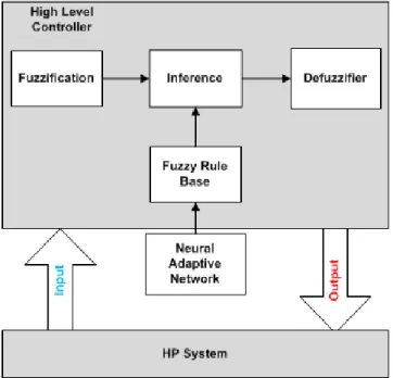
Figure 1.1 – Adaptative Neural Fuzzy Inference System (ANFIS) Controller Architecture. ... 3 Figure 2.1 – Circular-charts comparing operating costs and energy efficiency among the
three most common used solutions [2] ... 6
Figure 2.2 – Temperature-Entropy Chart of the Thermodynamic ideal Carnot Cycle. ... 6 Figure 2.3 – Temperature-Entropy Chart of the Thermodynamic Carnot Cycle usual
implemented. ... 7
Figure 2.4 – Heat Pump Basic Operation Cycles ... 8 Figure 2.5 –Hp Components a) Compressor b) Condenser c) Evaporator ... 9 Figure 2.6 – Typical ASHPWH Modules; Coil around the Tank and Coil emmerged in the
Tank ... 12
Figure 2.7 – Heat Pump ERP Energy-Label ... 14 Figure 2.8 – Thermal Stratification within Water Tanks, Cold water is represented by the
blue and red represents hot water ... 19
Figure 2.9 – Numericals results of temperature alogn the tank height and time, only
natural convection, Tamb=20ºC and To=70ºC [14] ... 20
Figure 2.10 – One Dimensional model Schematic, division in N equivalent Layers [10] ... 22 Figure 2.11 – Comparison between one-dimensional multinode with inversion, mean and
two-dimensional models. Tamb=20ºC and T0=70ºC [14]...24
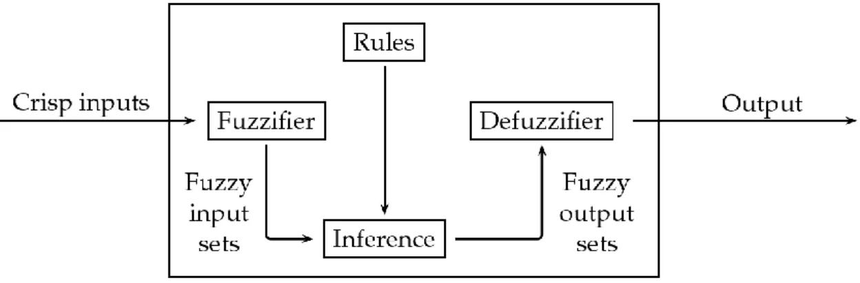
Figure 2.12 – Triangular Membership Functions ... 25 Figure 2.13 – Fuzzy Logic Controller Architecture ... 27
xv
Figure 2.14 – Mamdani Inference System [2] ... 28
Figure 2.15 – Takagi-Sugeno Inference System [2] ... 28
Figure 2.16 – Artifical Neuron Unit ... 29
Figure 2.17 – Neural Network Architecture ... 30
Figure 2.18 – INSTAR and OUTSTAR Neurons ... 34
Figure 2.19 – ANFIS architecture ... 35
Figure 3.1 – Heat Pump Model Prototype ... 38
Figure 3.2 – Heat Pump Model Construction ... 38
Figure 3.3 – Heat Pump Model Components ... 39
Figure 3.4 – Simulink Subsytem of Heating Module ... 40
Figure 3.5 – Simulink Subsystem of Energy Conservation Flow Temperature ... 42
Figure 3.6 – Simulink Subsystem of Energy Electronic Flow Estimator ... 43
Figure 3.7 – The First Graph represents the layers temperatures with no looses, the second one temperatures gradient in a day with thermal looses to environment Tamb=10ºC .. 44
Figure 3.8 – Flow Movements in Layer Division Thermal Stratified Tank... 45
Figure 3.9 – Simulink Subsytem of Thermal Stratified One-Dimensional Model ... 46
Figure 3.10 – Estimated Volume Vs Real Volume ... 47
Figure 3.11 – Volume Estimation with Priority Function Vs Real Volume ... 48
Figure 3.12 –Layers Temperature from the Validation Test, a consumption cycle of 250L then a heating up cycle. Tref=54ºC; Tamb=10ºC ... 48
Figure 3.13 – Smart Controller Design ... 50
Figure 3.14 – Hot Water Consumption Litres/Day ... 51
Figure 3.15 – Mean Water Consumption by Number of Occupants ... 51
Figure 3.16 – 2013 Air Temperature, Aveiro Portugal ... 52
Figure 3.17 – Learning Machine ... 54
Figure 3.18 – Air Temperature MF's ... 55
xvi
Figure 3.20 – Set Point Output MF's ... 56
Figure 3.21 – HP Status Output MF's ... 57
Figure 3.22 – Operation Mode MF's... 57
Figure 3.23 – Implementation Level of FLC ... 58
Figure 3.24 – Top Layers Temperatures, Smart Controller Vs No Controller ... 59
Figure 3.25 – Heating Power, Smart Controller Vs No Controller ... 59
Figure 3.26 – a) Heat Pump Heating Periods, Smart Controller Vs No Controller; b) Daily Temperatures ... 60
Figure 3.27 – Air FLC influence on Heating Power; SC Vs No Controller ... 61
Figure 3.28 –Total Daily Heat Transferred, Q ... 62
xviii
List of Tables
Table 2.1 — Heat Pump Test Conditions by EN 16174:2011 [5]. ... 12 Table 2.2 — Fuzzy Logic Controller table of Rules [2] ... 16
xx
Abbreviations and Symbols
Abbreviations (alphabetical order)
ANFIS Adaptive Neural Fuzzy Inference System ASHPWH Air Source Heat Pump Water Heater COP Coefficient of Performance
DEEC Departamento de Engenharia Electrotécnica e de Computadores DLS Damped Least Squares
EU European Union
ERP Energy Related Product
FEUP Faculdade de Engenharia da Universidade do Porto
FL Fuzzy Logic
FLC Fuzzy Logic Controller
FR Fuzzy Rules
GmbH Gesellschaft mit beschränkter Haftung (Company with limited liability)
HP Heat-Pump
HMI Human Machine Interface MSE Mean Square Error
MF Membership Function
NN Neural Networks
NTC Negative Temperature Coefficient
R Regression
S.A. Sociedade Anónima
SC Smart Controller
Symbols List
xxi
A Superficial Area
C Heat Capacity
ºC Temperature Degree Celsius
CC Corrective Factor due to electric mode g Gravitational acceleration
G Irradiation
h Heat Transfer Coefficient hi Initial Enthalpy
hTop Top Enthalpy hBot Bottom Enthalpy
L Length M Mass ̇ Mass Flow N Number of Layers ηH Heating Efficiency ηC Cooling Efficiency ηD Discharging Efficiency
qcond Heat Transfer Quantity of conduction
qconvec Heat Transfer Quantity of convection
qrad Heat Transfer Quantity of radiation
Q Heat
Qa Heat Power Transmitted to the Hot Source Qb Heat Power Absorbed in the Cold Source QHot Heat Transmitted to the Hot Source
QCold Heat Absorbed in the Cold Source
Qelec Total Heat include Looses
Qelec,week,smart Heat Power of Heat Pump System in the Week with Smart Mode
Qelec,week Heat Power of Heat Pump System in the Week without Smart Mode
Qref Heat Power of reference Tapping Profile
T Temperature
Tamb Ambient Temperature
Ts Surface Temperature
Tf Fluid Temperature
Tsurr Surroundings Temperature
Tcond Temperature in the Condenser
Tevap Temperature in the Evaporator
Tin Temperature Water inlet Tout Temperature Water outlet
TTop Temperature at the Top of the Tank Tbot Temperature at the Bottom of the Tank
xxii
Tref Temperature Set-Point of the Tank TW Temperature in Water Tank Walls U Overall Heat Transfer Coefficient
V Volume
w Weight of Neuron Input
W Work Wc Compression Power Wt Expansion Power z Height α Absorptivity λ Thermal Conductivity δ Stefan-Boltzmann constant ρ Density
Chapter 1
Introduction
In this chapter it is made an introduction to this thesis. It is presented a brief explanation of the project and the motivation for it, followed by the description of the internship company and also a summary of the first proposed objectives.
1.1 - The Project
The Dissertation is the final discipline of MSc in Electrical and Computer Engineering and provides the opportunity to the students to develop a project in a business environment, in the form of an internship, it results from partnership between the Faculdade de Engenharia da Universidade do Porto (FEUP) and Bosch Termotecnologia S.A, and allows the enrichment of practical and work experience.
The entities involved intended to develop a new control software that will be integrated into a Heat Pump, to a model already on the market and developed, which with appropriate modifications should be able to acquire information from the user profile, water consumption, implementing this way a smart controller with inherent COP (Coefficient of Performance) and comfort increase of HP (Heat-Pump) appliances.
This final report includes, in first place, the introduction and contextualization of the project developed, then the state of the art technologies for the issues addressed, the system description and problems, followed by the procedure and solutions adopted and the final results.
1.2 - Motivation
Nowadays, the population is in constant contact and need of equipments responsible for thermal processing with difference purposes, air conditioning, refrigeration machines, boilers, solar, heat-pumps. In this dissertation, it is discussed the application of HP System applications for water heating.
The market share of Heat-Pump systems equipments has increased significantly, mainly due to their environmental benefits and efficiency. Heat-Pumps don’t consume any fossil
2 Introduction
fuel, thus consequently they don’t send any pollutants to the atmosphere and they consume low electricity, so the investment of buying a water heating system based in Heat-Pump will pay back to the user after some time.
As the market for heat pumps is still emerging, the search for maximum efficiency means requires optimization of every aspect. The integration of a SC (Smart Controller), recent and widely used in various technological areas which are devices capable to build in one complete automation solution with advanced features like scheduling, adaptation and learning. In this case, we intend to develop the controller able to adapt and learn the user's water consumption and consequently increase user comfort, and overall system efficiency.
Besides the presented facts, this dissertation is an attractive opportunity to for development and innovation in a leading company which offers excellent conditions and working resources as well as an environment of professionalism and rigor.
Bosch Termotecnologia S.A is the centre of development and innovation of the group Robert Bosch in Domestic Hot Water products. The proposed project aims to use new methods in constant development with known potential which should increase the efficiency and effectiveness of the system and whose domain will certainly be an asset for future projects.
1.3 - Company Presentation
The group Robert Bosch GmbH (known as Bosch), named directly after its founder, Robert Bosch (1861-1942) is a German company founded in Stuttgart in 1886 as Mechanical and Electrical Engineering Workshop.
Currently, the Bosch Group is a leader in global technology and services, active in multiple areas such as: automotive, power technology, industrial goods, construction, and thermo technology. It is has more than 306 000 employees around the world generating revenue of 52.3 billion Euros.
The company success is based on a continuous investment in development, research and manufacturing which promotes the company's future and continuity. The Bosch Group has spent about 4.5 billion Euros in research and development originating to 4700 patents worldwide.
The products and services, of the Bosch Group, are designed and constructed to inspire, to fascinate and improve quality of life by providing innovative solutions.
Bosch Termotecnologia S.A
Under the heading name of Vulcano Termodomésticos S.A., the company started the its activity in 1977, in Cacia, Aveiro, operating under a licensing agreement with Robert Bosch GmbH.
In 1983, the Bosch Group acquired Vulcano, and by transferring expertise and equipments began a process of specialization within the Group.
Bosch Termotecnologia S.A focuses on the design, development, production and marketing of new technology and products at Domestic Water Heaters, including wall-mounted boilers, solar heating and heat-pumps.
Objectives 3
1.4 - Objectives
The main target of this project is to develop a new control Software, compliant with the European Standard EN 16147-2011 and ERP (Energy Related Products), able to acquire information from the user profile (Water Consumption) in order to guarantee the maximum comfort, implementing in this way a smart controller with inherent COP increase of Heat-Pump appliances.
Nowadays HP control is based on a user defined set-point, water and air temperature crisp values obtained from sensors. By using a Fuzzy Logic Controller (FLC) it will be able to keep the water at a desired temperature by activating/deactivating the compressor and auxiliary electrical elements, changing the expansion valve aperture and regulating the ventilator and water pump speeds based on the set-point, water and air temperature input, but the control law is implemented incorporating the user experience with Fuzzy Rules (FR).
To understand the user profile a software module should be implemented which will be able to automatically learn the user profile and adapt the Fuzzy Inference Engine.
At the end of this implementation the customer will benefit with a higher COP and also with a smart functionality that provides increased comfort.
The controller should be capable to maintain the temperature close to the reference programmed for every operating condition. It should also guarantee the easy adaptation to new configurations of heat pumps, and the compatibility with the existing hardware or at least with only some minimal modifications.
The values provided by temperature sensors are the inputs to the controller while the output is the actuators reaction to keep the system as desired.
The following image represents a high level of the FLC architecture in relation with a Neural Network (NN) and the low level model, according to the description above.
4 Introduction
In order to achieve the main goal of having the SC to learn, adapt and control the HP, previously the following objectives were defined:
Software and HP programming capacities; Modelling the HP System;
Design the ANFIS architecture;
Simulation of the model plus the ANFIS controller; Implementation of the controller in the HP system; Testing and Tuning;
Conclusions - COP Analysis.
1.5 - Document Structure
This document is divided in 4 chapters. Each contains several subsections according to the subjects mentioned.
Chapter 2 – State of Art: A compilation of all study available literature on the topic and
contextualization of the current work in stream with academic development. Analyses of the benefits and the weakness of the currents solutions are also performed.
Chapter 3 – System Modelling: Details the proposed solution design, simulation
procedure, achieved results and model validation compared to a real HP system. Therefore, the development of the SC and the results from its implementation are shown.
Chapter 4 – Conclusions: Presents an overview of the project; final conclusions are made
Chapter 2
State of Art
This chapter introduces the theoretical framework that underpins the matters dealt within the dissertation and current state of development of the technologies used. It synthesizes the literature related to the theme of HP’s, as well as the development of controllers based in FL and ANFIS, it also analyses the strengths and the weaknesses of current solutions adopted.
This section briefly shows a set of data and knowledge, which constitute the starting point of the study.
It is divided in three main sections: the first one concerns HP in general but focused on the Air Source Heat Pump Water Heater, the second one a review on Thermodynamics and Fluid Mechanics and for the last one refers to FL, NN and integrated ANFIS (Adaptive Neuro-Fuzzy Inference System).
2.1- Heat-Pumps
The development of HP technology was encouraged by the need of a new techno solution after fuel crises that lead to high fuel prices and also due to global ecology concern about the pollution causes from burning fossil fuels and theirs effects to the planet and to human life. The applications of environmental laws also eco-friendly subsidies, from several countries, to diverse products encourage people to install systems able to acclimate and warm water without the need to consume fuel.
The idea at the basis of the appearance of the HP it’s the energy transfer in form of heat, from one location to another, thus the HP don’t consume any fossils fuels neither send any dangerous pollutants to the atmosphere. HP’s have high efficiency comparing the electrical energy consumed and the quantity of heat produced. Comparing the most used domestic water heaters systems, gas, fuel boilers and the HP, in terms of operating costs and energy efficient, HP will show better results, as shown in Fig.2.1.
6 State of Art
Figure 2.1
–
Circular-charts comparing operating costs and energy efficiency among the three most common used solutions [1]2.1.1- Operation Principle
Heat Pumps technology is based on the Carnot Cycle, which is known from thermodynamics that is the principle most efficiently to transfer heat from two different temperatures, receiving heat from a hot source and sending it to a cold one. In order to contradict the natural impossibility of transferring heat from a lower to a higher temperature it’s necessary to provide work to the system and under these conditions we obtain the reversed Carnot Cycle [2] [3].
The ideal Carnot cycle is based on four different phases and is described by the graph in Fig.2.2, the four phases are:
Isentropic Compression [1-2]; Isobaric Condensation [2-3]; Isenthalpic Expansion [3-4]; Isobaric Evaporation [4-1];
Heat Pumps 7
Although the Carnot Cycle has a high coefficient of thermal transference between two different temperatures, until now unfortunately has not been possible to implement it previously, i.e. the cycle showed in Fig.2.2 cannot be represented in practice, there isn’t a Carnot Machine. At HP system this problem has different origins, the most frequently ones are: turbine characteristics, isotherm heat exchangers and the control of set-point, thresholds of condensation/evaporation. Thus, the Carnot cycle implemented at HP is similar to the following:
Figure 2.3 – Temperature-Entropy Chart of the thermodynamic Carnot cycle usual implemented
The cycle illustrated on Fig.2.3 comprises the four transformations between the represented points 1, 2, 3 and 4, where:
Path 1 to 2 adiabatic compression (Wc): The system performs work so that the pressure rises and therefore the temperature of the fluid/gas rises as well;
Path 2 to 3 isotherm heat exchange (Qa): Superheated steam is condensed over time, and is in contact with the hot source, it will receive part of the heat released in this condensation.
Path 3 to 4 adiabatic expansion (Wt): There is no heat transfer in this process; the pressure lowers and consequently also the temperature lowers.
Path 4 to 1 isotherm Heat Exchange (Qb): Heat exchanges between the hot source and the fluid/gas, cold source, which receives heat from the external source.
The four processes listed occur through different elements. In the case of the HP, 2 to 3 and 4 to 1, take place through elements that maximize heat transfer between the different surfaces in contact, such as heat exchangers, composed by the condenser and the evaporator. The two remaining steps are achieved using an electric compressor, 1 to 2, and an expansion device, 3 to 4, like a valve.
8 State of Art
2.1.2-Operation Cycles
Heat pumps have two main operating cycles, represented in the Fig.2.4 that represents its principal modes of operation: heating and cooling [1].
Figure 2.4 – Heat Pump Basic Operation cycles
Heating Cycle:
In the heating cycle, the normal operation is only guaranteed if the coolant is either in liquid or gaseous state.
Initially, the compressor provides work to the liquid/gas which is at low pressure and temperature, causing an increase in pressure and consequently an increase in temperature. Then this superheated gas is cooled, transferring heat to the hot source, and begins the condensation in the heat exchanger, until there is only liquid only at a very low temperature. To finish and restart the cycle, the liquid undergoes an adiabatic expansion in the expansion valve becoming the liquid/gas and is then ready to restarting.
Cooling Cycle:
In the cooling cycle, the basic operation is the same but the heat permutations are inversed compared to the previous explanation, since the objective is also the reverse.
A third cycle may also be considered, known as Defrosting Cycle, but it’s a simple iterative changing between the Cooling and Heating cycles, that normally happens to protect the equipment components.
Heat pumps, as already mentioned, has a great advantage the possibility to reverse the cycle, so some solutions may be able to perform both cycles, running either as heaters or as air conditioners.
2.1.3- Components
The HP basic components, Fig.2.5, to implement the Carnot cycle and assure the normal Heat and Cooling cycles are:
Heat Pumps 9
Refrigerant: Fluid and/or gas, normally biphasic, with low boiling point. It will be the
transporter of the Heat;
Compressor: It’s one of the key components and it’s responsible to provide work to
the system with adiabatic compression to the fluid; The fluid enters the compressor in the physic state of steam and it’s compressed to higher temperatures;
Expansion Device: Responsible for the isentropic expansion of the refrigerant; The
fluid is expanded returning to low values of temperatures and pressure;
Heat Exchanger: Composed by the Condenser and the Evaporator. It is responsible
for the heat exchanges between the fluid and the sources, cold and hot. The condenser isn’t more than a plate heat exchanger with two circuits, the hydraulic and the heated refrigerant. The evaporator is a finned tubes heat exchanger, wherein the refrigerant receives heat from the cold source;
Fan: Allows to pull and circulate air inside the Evaporator to increase the heat rate
transfer;
Temperature Sensors: General Control of the cycles and prevention of material
damage;
Accumulator: Small container that works as buffer to accumulate the heat, it’s
known in common sense as the water tank;
Figure 2.5 – HP Components; a) Compressor; b) Condenser; c) Evaporator;
2.1.4- Heat Sources
The cold source can be from different types: Air, Water or Underground. This choice depends essentially from the follow factors: characteristics of the external environment; limitations of legislative order; income required; cost of installation; time of pay-off, return of the investment [2][4].
10 State of Art
Air
It’s always available and can be captured from the outside environment or from an inside division of the house. Normally is the cheapest solution as it doesn’t need any special equipment or special licensing. Nevertheless the temperature thresholds must be take into consideration, because air temperature under 5-10ºC will drop the COP significantly.
Water
Heat Pumps appliances can also use water as a cold source, under normal conditions all water sources can be used, such as rivers, lakes, sea water or water wells. In the winter, low temperatures can diminish the COP decrease too, or in the worst scenario, if the water gets frozen all HP system can get in dangerous and be damaged.
Underground
Large amount of stored energy can be found on the underground. The source is solar near the surface and geothermal in deeper areas. In specific global regions with volcanic activity the geothermic energy is very high making this solution a very profitable.
2.1.5- Coefficient of Performance
The efficiency of a heat pump can be measured and controlled in well-established tests conditions. The COP value is used as reference result to compare their efficiency the COP is used. The COP is the ratio between thermal energy supplied to the hot source and the work provided to carry out the process. As a first observation we can see that no HP may have a higher COP than the COP of the theoretic reversed Carnot Cycle, the theoretic COP. The theoretic COP is then calculated by the following equations.
From the formulas above it’s possible to obtain that in the heating mode, the COP decreases when the outside temperature (QCold) gets lower or when the desirable temperature of the system (QHot, in the case of HP, water temperature) is very high.
The theoretic COP is a theoretic value refereeing to a machine operating in ideal conditions. To calculate the real COP it must be taken into consideration a corrective factor to the COP, the coefficient of performance.
In order to avoid over sizing of the system and result in unnecessary costs, each HP should be dimensioned according to the type and purpose it will operate most of the time.
Heat Pumps 11
The COP is the coefficient used to compare HP between manufacturers and models in certain markets, such as the European, this COP should remain within a threshold to comply with legislated standards that are very restricted.
2.1.6- Air Source Heat Pump Domestic Water Heater
After discussing the overall operation of Heat Pump Systems, in this chapter the focus will be given on the application which will be the subject of this dissertation, the Air Source Heat Pump Water Heater (ASHPWH). The main characteristic is the addition of a water tank and the possibility to integrate auxiliary heating elements. This water tank will allow reducing of the number of times compressor starts, saving electric energy, and regulating the water temperature.
These tanks are also named as accumulators of inertia and include two main functions: hydraulic separation and thermal flywheel [1]. This separation allows for the independence of the hydraulic flow and the heat flow, because hydraulic and thermal requirements are quite different, especially when used with variable consumption flow rate.
The cycle of operation is very similar to general HP, already explained in sections 2.1.1 and 2.1.2, except that in this case the superheated steam through the condenser is in contact with the water, and the heat is transmitted to it.
The heat transfers to the water in the accumulator and the heated water or the hot source can be performed in different ways. These heat transfers are conventionally classified in indirect and direct heating mode, which will consequently correspond to different ASHPWH configurations.
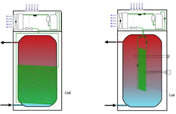
The most common configurations employed for indirect heating are: immersed tubes or coils in the tank, external shell-and-tube exchanger, and mantle heat exchanger. In the first solution the hot external fluid flows through a coil inserted inside the tank and allows the heat to be transferred to the water inside the accumulator. In the case of an external exchanger, the water is accumulated at the tank and will be pushed by a water-pump to receive heat inside the heat-exchanger and then will return to the tank. Those are the two most commonly used configurations because of their energy and heat transfer efficiency. The mantle exchanger normally provides a large heat transfer area and it’s the simplest and cheapest solution, although its efficiency isn’t as higher as the previous solutions [2] [4].
ASHPWH also allows the possibility to connect external equipments that will increase the performance of the system. These external equipments can be boilers, solar panels which can flow theirs hot fluids to a heat exchanger in contact with water tank, transferring heat to the water, and hydraulic flows from HP and external equipments cannot mix up. Photovoltaic panels can be used to feed the electrical needs of the HP, saving energy costs.
Two schematics of HP are at Fig.2.6 represent the two main used configurations available at markets, coil around the immersed coil.
12 State of Art
Figure 2.6 – Typical ASHPWH Modules, Coil around the Tank and Coil inside the Tank
2.1.7- EN 16147-2011
The efficiency of a heat pump is measured and controlled in well-established test conditions. In the European market the responsible entity CEN (Comité Européen de
Normalisation). The standard EN 16147-2011 was proposed to replace the previously EN255-3
and the main changes are: the COP is now lower than before, therefore this change in the requirement it’s because now the loses through the water tank are also take into account to the calculation the COP. The second main change is the introduction of five different categories (S, M, L, XL and XXL) to different tank sizes.
The European standard 16147-2011 specifies these same tests and methods for all topologies of heat pump or electric heating including tanks for the purpose of heating water compressors. These conditions are determined taking into account the heat source and the ambient temperature of the same pump. In the Table.2.1 the main conditions and parameters of the test [5] can be observed:
Heat Pumps 13
The standard establishes a sequence of operations to perform in the HP. The six main phases of this test are [5]:
Heating Period – Time needed to heat the tank from the initial state to the first “reset/turn-off” of the compressor;
Determination of Energy Consumption at Standby Mode;
Determination of COP and Energy Consumption for five different test cycles;
Determination of maximum water temperature and the amount of water usable after a cycle. The water temperature is measure at the exit of the tank after the compressor turns off;
Operating Temperatures Range;
Safety Test;
After performing these tests the HP, if the values are in agreement with the defined limits, the HP will receive permission to be commercialized, or get eco friendly benefits from the governments [5].
2.1.8- ERP
The ERP directive, from the European Parliament and Council, it is the standard that defines the labelling of product information, of energy consumption and others resources, to energy-related products [6].
This regulation establishes the requirements for energy labelling and supplementary product information on space or water heaters with a rated heat output ≤ 70 kW. The energy consumed by these heaters exhibits a wide disparity in terms of energy efficiency. Thus, the scope of this standard is to reduce their energy consumptions significantly, to provide incentives for manufacturers to develop energy efficiency heaters and encourage end-users to purchase the best energy-efficient products.
The information provided on the label, Fig.2.7, should be obtained through reliable, accurate and reproducible measurement and calculation procedures that take into account recognised state-of-the-art measurement and calculation methods including, where available, harmonised standards adopted by the European legislation.
Smart Controllers, functionality that automatically adopts the water heating to individual usage will be taken considered a positive factor to the final water heating energy efficiency class.
14 State of Art
Where Qref is the tapping profile, CC is a negative factor due to only electrical source,
Qelec is total heat including losses, Qcor is the ambience correction term, SFC is the gain due to
the use of Smart Controller and the Smart will be 0 if SFC < 0.07 or 1 if SFC ≥ 0.07. Consequently if the Smart Controller provides a good SFC it will improve the efficiency and consequently the ERP class.
Figure 2.7 – Heat Pump ERP Energy-Label
2.2- Thermodynamics and Mechanic Considerations
In order to understand the Mechanics concepts behind the HP operation and particular the water circuit heat exchanges and flow circulation, a review of basic fundaments about thermodynamics, thermal performance and behaviour of domestic hot water storage tank and thermal stratification is made [7].
2.2.1- Thermodynamics Principles
Thermodynamics is based in a group of physic principles concerned with heat, temperature and their relation to work and energy and the interaction of a system with the surroundings. Thermodynamics focus in the end states of the process during which an interaction occurs. It defines macroscopic variables such as internal energy, entropy and pressure. It is based in four laws that define fundamental physical quantities behaviour under particular conditions, the four principle thermodynamics laws:
Zero Law: If two systems are in thermal equilibrium with a third system, they both must
be in thermal equilibrium;
First Law (The law of conservation of energy): due to energy conservation basic
principle, the internal energy variation its equal to the total energy received or transmitted to the extern. , where ΔU is the variation of the internal energy of the system, Q is the heat supplied and W the work done by the system.
Thermodynamics Principles 15
Second Law: the entropy of any system cannot decrease; such system spontaneously
evolves towards thermodynamic equilibrium, state of maximum entropy of the system.
Third Law: The entropy of any pure substance in a thermodynamic equilibrium
approaches zero as long the temperature also approaches zero.
Thermal Conductivity (λ – W/m*K): quantifies the ability of a material to conduct
thermal energy, heat. Materials with high λ transmit heat at high rate. In this case the two materials of interest are water and air. They have, at ambient temperature (T=27ºC), respectively, λ=0.61 and λ=0.024; Where L is the length, A the area;
Heat Capacity (C – J/Kg*K): is the relation between the quantity of heat supplied and the
variation of temperature observed in a object, is an extensive property of matter, its proportional to the size of the system.
These thermodynamics analysis are related to the study of modes of heat transfers and heat transfers rates calculations.
2.2.2- Means of Heat Transfer
A Heat Transfer consequently, occurs every time that exist a temperature difference in a medium or between systems. So, a Heat Transfer is thermal energy in transit due to a temperature difference. This heat movement can be classified in three main modes: Conduction, Convection and Radiation.
Conduction:
The energy transfer by conduction refers to the levels of atomic and molecular activity. It can be seen in a simple way as the transfer of energy from the more energetic to the less particles of a substance due to the interaction between the particles.
Higher temperatures correspond to higher molecular energy, causing neighbouring molecules to collide constantly creating the temperature gradient between the higher energetic to the less energetic.
This molecular activity is more remarkable in gases. However, it also happens in liquids and solids of course. In the liquids, molecular interactions are stronger and more frequent. In the solids, this can be attributed to atomic activity in the form of lattice vibrations.
The Heat Transfer quantity can be calculated in terms of rate equations, i.e., the amount of energy being transferred per unit of time. For one dimensional structure, which has a T(x) temperature distribution the rate equation is expressed in the following Eq. (2.9 – 2.10).
16 State of Art Convection:
This heat transfer mode includes two mechanisms of energy movements, beyond the previously molecular diffusion, also present at conduction. The energy is also transferred in a macroscopic motion of the fluid. It means that any instant large numbers of molecules are moving as aggregates, such motion in presence of a temperature gradient contributes to heat transfer.
When there is a contact between a fluid in motion and a bounding surface with, as result of this interaction, there is the development of a region in the fluid through which the velocity varies, this region is known as “Hydrodynamic” or “Boundary Layer”. Moreover, if the surface and flow temperatures differ there will be a region of fluid through which the temperatures varies and it will become called “Thermal Boundary Layer”. The diffusion energy transfer dominates near the surface of the Thermal Boundary Layer where the fluid velocity is very low, almost zero. On the contrary, the contribution of the motion of fluid will be more felt as more as the flow progresses in the x direction, and eventually transmitted to others layers. This movement of the fluid will play a vital role in our later analysis of convection to design our model.
Convection heat transfers may be caused intentionally or happen naturally path. We speak in forced convection when the flow is caused by external devices, such as fans, water pumps. In contrast, free convection the flow appears due to buoyancy forces, which arises from density differences cause by the difference of temperatures. Both phenomenons are presents in an ASHPWH.
As we described it, the convection energy transfer occurs within a fluid due to these combined effects and it is related to the internal energy. So, including the two mechanisms and regardless the nature of convection, the rate equation is expressed by:
This expression is known as “Newton’s Law of Cooling”, where h is the convection heat transfer coefficient, who depends on conditions such as the boundary layer which are influenced by the surface geometry, the nature of the fluid motion and an assortment of fluid thermal and transport properties.
Radiation:
Thermal radiation is the energy emitted by matter at a finite temperature. It may occur in all physic states, solid, liquid or gases, but is more common in solids. Regardless the form of matter, the radiation emission may be attributed to changes in the electrons configurations of constituent atoms/molecules.
Radiations energy transfer doesn’t need the any material medium. The energy is transported by electromagnetic waves. The radiation transfer processes is modelled by the Stefan-Boltzmann law adapted, the flux emitted by a surface is:
Thermodynamics Principles 17
Where (ε) is the radioactive property of the material, emissivity (0≤ε≤1). It provides a degree of efficiency of emitting energy comparing to a blackbody, and σ is the Stefan-Boltzmann constant.
Radiation can also come from the outside of the system, from external sources, such as the sun or other surfaces emitting radiation which our system is exposed to. This radiation or part of it may be absorbed increasing the thermal energy of the material. The rate at which this received energy is absorbed per unit surface area may be calculated from the knowledge of the surface’s properties:
Where
is the absorptivty, ranging between 0≤ α ≤1, depending in the material properties.
In Radiation transfers is very common the case of energy exchanges between a small and a very large surface, which involves the smaller one. The radiation heat exchange ratio per unit of time can be expressed and calculated, considering all the situations above, emitted and/or absorbed energy or even surroundings temperatures:
First Law of Thermodynamics and Heat Transfers:
The control Volume is a region of space bounded by a control surface within energy and matter may pass. The first law must be satisfied at each and every instant of time, or over a time interval, i.e. it must exist a balance between all energy rates. The rate at which thermal and mechanical energy enters a control volume, plus the rate at which thermal energy is generated within the control volume, minus the rate at which thermal and mechanical energy leaves the control volume must equal the rate of increase of energy stored within the control volume.
If the inflow and generation of energy exceeds the outflow then there will be an increase of the energy storage. In other hand, if the outflow is higher, then it will decrease the system energy. If there won’t be any change in the amount of energy stored.
At an instant of time, applying the energy conservation rule to the control volume, the power specifications, including the rate which thermal and mechanical energy entering, and leaving, , and the energy generation on storage must be taken into account to calculate the rate of change of energy stored within the control volume, Est.
The inflow and outflow terms are phenomenon exclusively related with processes occurring at the control surface, involving typically heats transfers, fluid flow circulation or work interactions. The energy generator is related to energy to thermal energy transformations by different processes (ex: electric heating caused by current passing at
18 State of Art
conductor), but also to volumetric phenomenon caused by internal changes at potential energies.
The Eq.2.15 can be related with previous concepts studies of thermodynamics in order to develop more specific forms of the energy conservation requirement equations. As written in the first law of thermodynamics, if over a time interval, heat is transferred to the system, there will be work done in the same amount. In this case, there isn’t energy conversion, so and potential energy changes are negligible, so the Eq.2.16 will now be reduced to:
Other interesting form of the energy conservation law requirement, which is very important and related to ASHPWH, it is when an open system mass flow provides transport of energy into and out of itself. Therefore, the system will have the contribution from the work done by pressure forces of the moving fluid through and the energy storage will be zero, , and so the equation 2.15 will be reduced to:
( ) ( ) ̇
2.2.3- Thermal Stratification
After this brief thermodynamics initiation, it will be discussed the thermal behaviour of the water inside storages tanks. In order to sufficient store and use high-quality heat-energy, water tank thermal stratification is widely applied in many kinds of energy storage fields, and the ASHPWH aren’t exception [8] [9].
Thermal stratification phenomenon is mostly concentrated in air or liquid mediums. The researches of thermal stratification within the tanks has been studied intensively since the 1970s, motivated from the unsteady characteristics of heating power and consume needs, thermal operation becomes very important in long-term operation of water heating. Its wide application lies in the minimization of the mixing effect which is cause by the thermal buoyancy as consequence of water temperatures differences. Studies showed that the presence of a good thermal stratification may improve the performance of the energy storage up to 6% to 20% by comparison to fully stratified water tanks.
The presence of water tanks in Water Heating systems is due to the difficult to keep in balance the energy requirements, the difference between the actual needs and power of heating, so with its presence it will be able to store energy for this redundancy.
Thermal Stratification Building: a domestic heating water system generally consist of
three main parts a heating loop, a user consumption loop and a water storage tank. The heating loop is responsible to heat water to higher temperatures and filled it in to the storage tank, the consumption loop will be active as the user needs or requires of hot water. There are two main situation of thermal stratification building: when there is a hot water tank without external flow and with external flow.
When a hot water tank without external flow is subjected to the ambient temperature, a thermal stratification is formed in the course of cooling process. Thus, the cooler water accumulates at the bottom while hot water ascends to the top, Fig.2.8. This phenomenon
Thermodynamics Principles 19
occurs even if initially the water inside the tank is at uniform temperature. It is originated from the fact that, prior to the releasing to the ambient the tank walls cools with a thin vertical layer. Part of this heat is transferred by diffusion from the core of the tank and other to the tank walls water [10].
When the heating loop is working the water coming from it is allowed to mix with the colder water inside the tank, causing the supplied temperature to be lowered and the quantity of energy to be decreased, causing the whole tank water to tend to a threshold. The point of using thermal stratification is to eliminate this effect. So when the hot fluid comes from the heating circuit, it will drop on a higher level of the tank where its density matches the density of surrounding fluid. Due to gravity and buoyant effect, water with different temperatures will deposit the corresponding height according to the density difference. Light density will bring the hot water to the top layers and cold one to the bottom. This thermal stratification will work as a barrier separating and maintain vertical temperature gradient. There are other ways to achieve this thermal stratification: heating of vertical walls; heat exchange between the fluids containing within the tank in the same direction of the temperature gradient.
Figure 2.8 – Thermal Stratification within water Tanks, cold water is represented by blue colour and
red represents hot water.
Thermal Stratification Perturbations: During the ASHPWH operation, fluid extracted
from the bottom of the tank is usually heated and returned to the top of the tank, simultaneous there is a consumption loop which will supply hot water and inject cold water at the bottom with equal rate flow. The turbulence generated by these operations may cause mixing if it is not confined to the right density layers.
Some geometric parameters can affect stratification within the water tank. These geometric factors include tank size, the aspect ratio of tank, and inlet port location and geometry. Moreover parameters related with operating conditions will also affect the thermal stratification, like flow velocity, initial and inlet tank water temperature difference [11].
As main studies about tank geometric parameters, Lavan and Thomson [12], performed experimental studies that showed better thermal stratification can be obtained increasing the relation between the height and diameter of the tank. Others studies suggest that select the height/diameter ratio in interval 3-5, can achieve maximum thermal stratification in the tank. It was also found that the inlet location had a strong influence on thermal stratification while the location of hot water to consumption could be negligible to thermal stratification
20 State of Art
formation and maintaining cold water inflow at the top of tank will completely mix up the temperature field inside the tank.
The influence of thermal leakage by the tank was also studied. Thermal diffusion through the water tank can be ignored because it doesn’t influence significantly the decay of thermal stratification in vertical tanks. However, it was shown that thermal degradation in tanks with thinner walls is more pronounced due to larger axial heat conduction in the tank wall. Following studies on the subject showed that in dynamic mode of operation, the effects of mixing of inlet and outflow water overtake the influence of this parameters, so this effect of wall loses must be taken in account wherein the tank is in static mode or in contact with a cold ambient temperatures.
In the Fig.2.9, it is possible to observe the typical temperature gradients from experimental results in a water tank influenced by the factors described above.
Figure 2.9– Numerical results of temperature along the tank height and time, only natural convection,
Tamb=20ºC and T0=70ºC [14].
Thermal Stratification Performance: In order to assess the efficiency improvement on
stratification, a standard should be lied down as a reference. This evaluating index will be difference for each tank and HP behaviour.
For static condition, the stratification number represents the ratio between the means of the temperature gradients at any time to the maximum mean temperature gradient.
The energy efficiency performance of the domestic hot water storage tank is evaluated by calculating the thermal energy stored in the tank and loses.
This energy efficiency may suffer alterations due to the operations conditions of the HP, so three main situations are take into account: heat process, cold process and discharging.
Thermodynamics Principles 21
During the heating period, the energy efficiency is defined as the ratio of the energy available at the tank to the energy supplied by the heating module at the instant.
In the cooling period, the energy efficiency is referred to the energy accumulated in the tank at the beginning of the process.
Finally at the discharging process, the transient discharging energy efficiency is defined as the ratio of the cumulative thermal energy delivered by the water leaving the tank to the initial thermal energy stored at the tank.
∫( )
2.2.4- Modelling
The development of mathematical model is one of the important aspects to study the thermal stratification within the tank. The study of thermal behaviour of the water inside the storage tank can be made either through experimental methods or numerical simulations. Mathematically this problem can be modelled based in the mass momentum and energy conservation equations. The numerical simulation can be implemented using all the differential equations that govern the tank, all its components and all the physical phenomena that occur inside the tank.
Most studies refer and use one-dimensional and two-dimensional models, i.e. related to the water movement’s considerations. It is assumed that water can move along the tank in radial and axial directions due to the temperature gradients. The one dimensional models only consider uniform temperature gradient over the axial length and the two-dimensional model considers both motions. The Fig.2.10 shows the typical division and the dynamics factors at the tank.
One-Dimensional: These models are easier, faster, and simple to be implemented in the
simulation of thermal stratification and temperature gradient in heat storage tanks. In the basis of these, it is assumed that along the flow direction the tank is divided in L equal elements, layers.
22 State of Art
Figure 2.10 – One dimensional schematic, division in N equivalent layers [10].
The first kind of model developed, the temperature-stratified type, consider a factor (δ), which is responsible to determine the position of the incoming flow. This factor will be binary, 0 or 1, and will be controlled by the temperature, comparing between the inlet temperature and the temperature of the actual layer.
̇ The others models, balanced ones, were built by Alizadeh [13]. The tank is also divided in L equal layers, the cold water enters at the bottom of the tank and is assumed to influence and mix with the ‘N’ first bottom layers, having no effect on the water in higher position than this point, and the mixing process is neglected by temperature-stratified consideration.
{[ ( ̇ )] ( ̇ ) } {[ ] }
In second model developed by Alizadeh [13], heat leaks from the ambient, conduction through thermo-cline and conduction from warm fluid to cold fluid layers conduction through wall and thermal mixing at inlet and outlet are considered.
̇
Since the physically movement of water happens in two dimensions, the successful use of one-dimensional models requires the inclusion of certain computational artifices, i.e. procedures that examine at each time step the distribution of temperatures and order them by decreasing temperature gradient. Two artifices with good results are presented by the author Franke [14] multinode with inversion and multinode with mean, respectively.
The multinode with inversion method consists in interchange the segments in a decreasing order, from the top to bottom of the tank, in function of theirs temperature. The highest
Thermodynamics Principles 23
temperature, at any given time, must be at the top of the tank and all the following layers follow the same rule, then the Layer above will always have higher temperature then the next.
The multinode with mean methods consists on the exempts the temperature inversion by the use of weighted of mean temperature among the layers involved in thermal inversion. In order to do so the layers are scanned in opposite directions and the point of inflexion of the curve is identified in the ascending way. A temperature weighted mean is identified in this layer and the layers immediately above and this mean will be valid for both segments. If a new inversion is identified during the scanning a new mean is calculated and at the end of this algorithm all the layers above the inflexion point will have the same temperature.
Two-Dimensional: These are more complex but also more representative of the reality.
The two-dimensional models concern natural and mixed convection, making use of the mass conservation Eq.2.27, momentum in axial Eq.2.28, radial directions Eq.2.28 and energy equations Eq.2.29. The governing equations are normally expressed in cylindrical coordinates due to the normal shape of the tank and to represent the effects of water moving easily. Below are the modelling equations in the simplest version in Cartesian coordinates:
( )
One-Dimensional Vs Two-Dimensional Results: Different studies had compared
experimental and real data with one dimensional and two dimensional models. These studies showed that two dimensional numerical simulations are very appropriate since its results were coherent and showed good agreement with the results from the experimental procedures, although their implementation and simulation requires high computational and mathematical analysis.
In the case of the one dimensional methods, simple models differ from actual behavior because it does not stratify the temperature segments in the tank except when there is significant external water circulation. This will be corrected by the use of the computational artifices. Due to this manipulations of the segment temperatures the difference between these results and those obtained with the two dimensional models will be very close. The Fig.2.11 shows the comparison between the One-dimensional and Two-Dimensional results.
24 State of Art
Figure 2.11 – Comparison between one-dimensional multinode with inversion, mean and
two-dimensional models. Tamb=20ºC and To=70ºC [14].
The one-dimensional multinode models are much faster than two-dimensional models. Thus considering the comparisons there isn’t any reason to use two-dimensional methods to simulate in long-term simulations of water heating systems. Nevertheless two-dimensional models can give detailed information about the behavior and are suitable to understand the thermal phenomena in the hot water storage tank.
2.3- Fuzzy Logic
Fuzzy Logic allows control and model systems. It surged as a response to the complex problems of the world, as they need not only mathematical or scientific resolution but also Human common sense knowledge. Thus a FLC will incorporate scientific knowledge with wisdom and general human culture that will influence the final decision of controller.
FL is a simple way to set an output based on inaccurate, vague or ambiguous input information. The method resembles the decision making of a human being, but faster and more accurate [16].
The FL was conceived by Lofti Zadeh, professor at the University of Berkeley in California. It was introduced in 1965, not as a method of control, but as a way of processing information through inaccurate and incomplete sets.
Zadeh’s theory is based on the fact that Human beings don’t need precise or numerical information to make decisions, and still be highly capable of providing adaptive control to systems. If closed loop controllers can be programmed to accept noisy and inaccurate input they would be even more effective and easy to implement.
Fuzzy Logic 25
In the late seventies, fuzzy logic began to be used in control systems due to the insufficient capacity of the computers of the time. In the early days, the theory was not widely accepted by the system manufacturers.
Nowadays, there are numerous applications of the Lofti Zadeh’s concept. It can be found in areas such as control, supervision and monitoring, decision support systems, classification of information, computer vision, pattern recognition and knowledge-based systems.
2.3.1- Fuzzy Sets
The Fuzzy Sets break the traditionally idea that something belongs to a group. Mathematically or traditionally, for example, if it is set that A = {Hot| x≥ 20ºC}, where x is the temperature measure in a room, if the actual temperature in the room is 19.99ºC it won’t be considered hot, but 20.01 ºC will. For people this small difference won’t probably be felt, but for the mathematical controller it would not reflect the real world and would give a different response in the control system
.
The Fuzzy Set breaks this paradigm by making the transition between sets gradual, using for this propose the membership functions, " Membership Functions" (MF).Membership Function
The MF indicates us the belong degree, for each variable to different groups. This degree will be calculated by values from 0 to 1. The MF is defined mathematically by the expression: {( )| }, where x is the valor of variable, µa is the MF degree and X is the linguist variable.
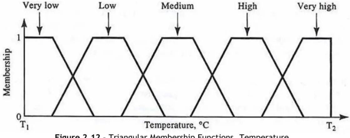
A Fuzzy set is completely described by its MF and in the Fig.2.12 it is possible to observe an example of a typical MF of Fuzzy sets.
Figure 2.12 – Triangular Membership Functions, Temperature
The MFs have some characteristics that can be useful to describe them or to find specific objectives:
Support: Set of points where µa(x) > 0;
Core: Set of points where µa(x) = 1;
Crossing Points: Set of points where µa(x) = 0.5;
![Figure 2.1 – Circular-charts comparing operating costs and energy efficiency among the three most common used solutions [1]](https://thumb-eu.123doks.com/thumbv2/123dok_br/18905269.935778/30.892.141.708.111.450/figure-circular-charts-comparing-operating-energy-efficiency-solutions.webp)
![Figure 2.9– Numerical results of temperature along the tank height and time, only natural convection, T amb =20ºC and T 0 =70ºC [14]](https://thumb-eu.123doks.com/thumbv2/123dok_br/18905269.935778/44.892.253.599.423.774/figure-numerical-results-temperature-tank-height-natural-convection.webp)
![Figure 2.10 – One dimensional schematic, division in N equivalent layers [10].](https://thumb-eu.123doks.com/thumbv2/123dok_br/18905269.935778/46.892.281.581.83.391/figure-one-dimensional-schematic-division-in-equivalent-layers.webp)

![Figure 2.14– Mamdani Inference System [2]](https://thumb-eu.123doks.com/thumbv2/123dok_br/18905269.935778/52.892.202.662.130.425/figure-mamdani-inference-system.webp)

