Oliveira, L. M. R. e Cardoso, A. J. M.: "Incipient turn-to-turn winding fault diagnosis of power transformers by the on-load exciting current Extended Park's Vector Approach"; Proc. Of the Advanced Research Workshop on Modern Transformers (ARWtr04), pp. 134-139, Vigo, Spain, 28-30 October, 2004
Advanced Research Workshop on Modern Transformers. ARWtr 2004 28 -30 October 2004. Vigo – Spain
Incipient turn-to-turn winding fault diagnosis of power transformers by the
on-load exciting current Extended Park's Vector Approach
L. M. R. OLIVEIRA (1) and A. J. MARQUES CARDOSO (2) (1) Escola Superior de Tecnologia da Universidade do Algarve, Portugal
Campus da Penha, P – 8005-139 Faro, Portugal
Phone: (+351) 289800100, fax: (+351) 289823539, e-mail: [email protected]
(2) Universidade de Coimbra, Departamento de Engenharia Electrotécnica e de Computadores, Portugal Pólo II - Pinhal de Marrocos, P – 3030-290 Coimbra, Portugal
Phone: (+351) 239796232, fax: (+351) 239796247, e-mail: [email protected]
Abstract —This paper presents the application of the
on-load exciting current Extended Park's Vector Approach for diagnosing incipient turn-to-turn winding faults in operating power transformers. Experimental and simulated test results demonstrate the effectiveness of the proposed technique, which is based on the spectral analysis of the AC component of
the on-load exciting current Park's Vector modulus.
Keywords — Transformers, winding faults, diagnostics,
Extended Park's Vector Approach.
I. INTRODUCTION
Power transformers are essential devices in a transmission and distribution system. Failure of a power transformer may cause a break in power supply and loss of profits. Therefore, it is of great importance to detect incipient failures in power transformers as early as possible, so that they can be switched off safely and improve the reliability of power systems [1].
The most difficult transformer winding fault for which to provide protection is the fault that initially involves only one turn [2]. Initially, the insulation breakdown leads to internal arcing, which results into a low current, high impedance fault [3]. Usually, this incipient inter-turn insulation failure does not draw sufficient current from the line to operate an ordinary overload circuit-breaker or even more sensitive balanced protective gear [4]-[6]. This turn--to-turn fault will then progress, with random propagation speed, involving additional turns and layers, leading to a high current, low impedance fault, [7], [8]. The transformer will, in fact, be disconnected from the line automatically when the fault has extended to such degree as to embrace a considerable portion of the affected winding [4].
Previous research, concerning the use of the Park's Vector Approach, has demonstrated the effectiveness of this non-invasive technique for diagnosing malfunctions in operating three-phase induction motors, power electronics and adjustable speed drives [9]. Preliminary experimental
results, presented in [10], concerning the use of the supply current Park's Vector Approach, have also demonstrated the effectiveness of this technique for diagnosing the occurrence of inter-turn insulation faults in the windings of operating three-phase transformers. The on-line diagnosis is based on identifying the appearance of an elliptic pattern, corresponding to the transformer supply current Park's Vector representation, whose ellipticity increases with the severity of the fault and whose major axis orientation is associated to the faulty phase. However, with this approach, it is difficult to discriminate between unbalanced loads and winding faults. To overcome this difficulty, an improved diagnostic technique was then implemented [11], [12], which consists in the analysis of the on-load exciting current Park's Vector pattern, and therefore unaffected by the transformer's load conditions. Additionally, the on-load exciting current Park's Vector Approach enhances the severity of the fault, as compared to the former diagnostic technique.
The on-load exciting current Park's Vector Approach takes into account the currents in all the three primary and secondary phases. Too much information is thus contained in this representation, which cannot be completely extracted by the analysis of the resulting geometrical pattern. Also, a fault severity factor cannot be easily defined.
Firstly applied to diagnose AC motors faults, a new technique has been introduced [13], the so-called Extended Park's Vector Approach (EPVA), in order to allow a more in-depth characterization of the unit condition.
This paper presents the integration of the on-load exciting current strategy with the EPVA to diagnose winding short--circuit faults in operating three-phase transformers.
II. ON-LOAD EXCITING CURRENT EXTENDED PARK'S VECTOR APPROACH
The on-load exciting current waveforms are computed by adding the primary and secondary winding currents, both referred to the primary side. For the YNyn0 winding
Advanced Research Workshop on Modern Transformers. ARWtr 2004 28 -30 October 2004. Vigo – Spain
connection (Fig. 1) the on-load exciting currents are:
1 1 4 2 2 5 3 3 6 e s p e s p e s p i i i N N i i i N N i i i N N = + ⋅ = + ⋅ = + ⋅ (1)
where Np and Ns are the numbers of turns of primary and
secondary windings, respectively. For the case of other transformer connections, the on-load exciting currents can be obtained by using the same basic principle, but with slightly different computations [11], [12].
The transformer on-load exciting current Park's Vector components (ieD, ieQ) are:
(
2 3 1 6)
1( )
2( )
1 6 3 eD e e e i = i − i − i (2)( )
1 2 1 2 2( )
3 eQ e e i = i − i (3)Under ideal conditions, the three-phase on-load exciting currents lead to a Park's Vector with the following components:
(
6 2)
sin( )
eD M i = i ωt (4)(
6 2)
sin(
2)
eQ M i = i ω − πt (5)where iM is the maximum value of the on-load exciting
current (A), ω is the angular supply frequency (rad/s) and t is the time variable (s). The corresponding representation is a circular locus centered at the origin of the coordinates. Under abnormal conditions equations (4) and (5) are no longer valid and consequently the observed picture differs from the reference pattern.
The Extended Park's Vector Approach (EPVA) is based on the spectral analysis of the AC level of the current Park's Vector modulus:
2 2
eD eQ eD eQ
i + j i = i +i (6)
Ideally, under healthy conditions, the EPVA signature will be clear from any spectral component, i.e., only a DC value is present in the current Park's Vector modulus.
In the presence of a primary winding fault, the short-circuited turns act as an autotransformer load on the winding, as shown in Fig. 2(a). However, if the fault takes place on the secondary winding, the short-circuited turns act as an ordinary double winding load, Fig. 2(b), [4]. In both cases, the occurrence of winding inter-turn short-circuits leads to an increment in the magnitude of the on-load exciting current in the affected phase, as compared to a healthy situation, which results in an unbalanced system of currents. Under these conditions the on-load exciting current Park's Vector modulus will contain a dominant DC level and an AC level, at twice the supply frequency (2f), whose existence is directly related to the
asymmetries in the transformer. The amplitude of this spectral component is directly related to the extension of the fault. In this way, an indicator of the degree of asymmetry can be defined as the ratio between the amplitude of the spectral component at the frequency of 2f and the DC level of the on-load exciting current Park's Vector [13]. The proposed fault severity factor (SF) is thus expressed by: ( ) 2 2 2 component 2 2 max average eD eQ f eD eQ i i SF i i + = + (7)
Further details of the theoretical principles related with the EPVA can be found in [13].
III. LABORATORY AND SIMULATION TEST RESULTS
For the experimental investigation a three-phase, three leg transformer, of 6 kVA, 220/127 V, was used. The transformer has four windings per limb, having two of them been modified by the addition of a number of tappings connected to the coils, allowing for the introduction of different percentages of shorted turns at several locations in the winding, as shown in Fig. 3 for the phase R of the transformer primary winding.
A shorting resistor was connected at the terminals of the faulty subwinding, whose value was chosen so as to create an effect strong enough to be easily visualised, but simultaneously big enough to limit the short-circuit current and thus protecting the test transformer from complete failure when the short is introduced.
The experimental study of winding inter-turn short-circuits occurrence presents some inherent difficulties: the current in the shorted turns must be limited to the rated current of the winding and the tappings location of the test transformer does not allow for the introduction of a small number of shorted turns, which, in this case, is limited to 5% (11 turns) of the whole winding (Fig. 3). Therefore, a detailed analysis of these phenomena can be better investigated by the additional use of a suitable digital simulation transformer model. For that purpose, a coupled electromagnetic transformer model was developed [11], [12], [14]-[16], which is based on the combination of both magnetic and electric lumped-parameters equivalent circuits, allowing for the modelling and simulation of the transformer in its natural technology.
A. EPVASignature Under Healthy Operation
Fig. 4(a) presents the experimental on-load exciting current Park's Vector pattern for the case of an YNyn0 winding connection, rated load conditions and for a healthy operation of the transformer. This pattern differs from the
Advanced Research Workshop on Modern Transformers. ARWtr 2004 28 -30 October 2004. Vigo – Spain n
R
S
T
1 i 2 i 3 i n 4 i 5 i 6 ir
s
t
1v
N
p Fault impedance 1i
4v
N
s 4i
1v
N
p Fault impedance 1i
4v
N
s 4i
f i f i U1 5% UA UB UC 10% 20% UD 5% UE X1 UF UG 20% 10% 5% 25%Figure 1. Transformer YNyn0 winding connection.
(a) (b)
Figure 2. Equivalent circuits for a fault occurring in the: (a) primary winding; (b) secondary winding, (phase R).
Figure 3. Location of the tappings for transformer primary winding (phase R).
circular locus expected for an ideal situation, due to, among others, the non-linear behaviour and asymmetry of the magnetic circuit. This is a well known phenomenon, which is revealed by the unbalanced and distorted nature of the exciting currents obtained from any three-phase no-load test. In fact, the exciting current Park's Vector pattern, obtained at no-load conditions, presents the same characteristics, as shown in Fig 4(b).
The corresponding EPVA signatures are shown in Fig. 5. As stated above, under ideal conditions, the EPVA signature would be clear from any spectral component. However, in practice, a spectral component with a small amplitude, at a frequency of 2f (100 Hz), is present, which is originated by the same reasons responsible for the deformation of the exciting current Park's Vector pattern. The corresponding simulated results are presented in Fig. 6, which are in close agreement with the experimental ones.
(a) (b)
Figure 4. Experimental on-load exciting current Park's Vector pattern (a) and no-load exciting current Park's Vector pattern (b) for the case of an
YNyn0 connection and healthy operating conditions.
(a)
(b)
Figure 5. EPVA signatures of the on-load (a) and the no-load (b) exciting currents for the case of an YNyn0 connection and healthy operating
conditions (experimental results).
(a) (b)
Figure 6. Simulated on-load exciting current Park's Vector pattern (a) and EPVA signature (b) for the case of an YNyn0 connection, rated load and
Advanced Research Workshop on Modern Transformers. ARWtr 2004 28 -30 October 2004. Vigo – Spain 2×In In healthy 4×In In healthy 4×In 2×In healthy 4×In 2×In In
B. EPVA Signatures Under Winding Inter-Turn Short-Circuit Faults
Several experimental tests were conducted in order to evaluate the transformer behaviour under the occurrence of shorted turns, using the available tappings locations and maintaining the faulty current within safe values. However, with this approach, it is not possible to introduce a low severity fault (like a turn-to-turn fault), which is intended to be detected by the proposed diagnostic technique. The severity of a winding fault depends not only on the number of shorted turns, but also on the value of the current in the faulty subwinding (if in Fig. 2), which is
limited by the fault impedance. As mentioned above, these two factors are affected by practical limitations of the test setup. For these reasons, it will be given more relevance to digital simulation results in this section.
Considering an YNyn0 winding connection and rated load conditions, Fig. 7 presents the simulated on-load exciting currents Park's Vector patterns, for the case of two shorted turns in the primary winding, with several values of faulty current (in terms of the rated current of the affected winding, In) and for different faulty phases. The occurrence
of primary-side inter-turn short-circuits manifests itself in the deformation of the on-load exciting current Park's Vector pattern corresponding to a healthy condition, leading to an elliptic representation, whose ellipticity increases with the severity of the fault and whose major axis orientation is associated to the faulty phase. Similar conclusions, concerning the on-load exciting current Park's Vector patterns, can be drawn for the occurrence of secondary inter-turn short circuits [12].
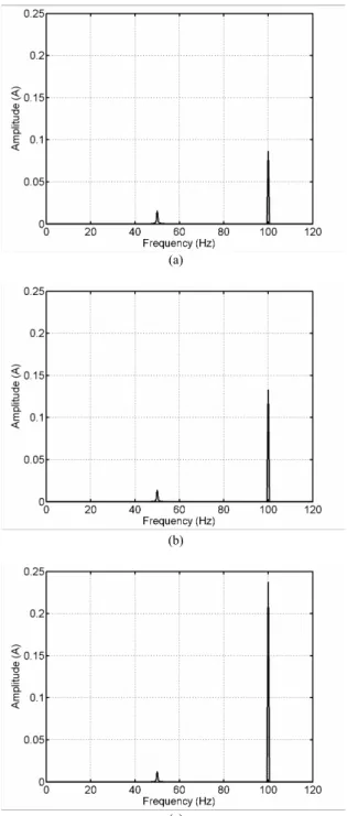
The corresponding EPVA signatures, for the case of phase
R primary winding defects and for several values of faulty
current, are shown in Fig. 8. It can be seen that the amplitude of the 2f spectral component (100 Hz) increases with the severity of the fault, representing a good indicator of an insulation defect.
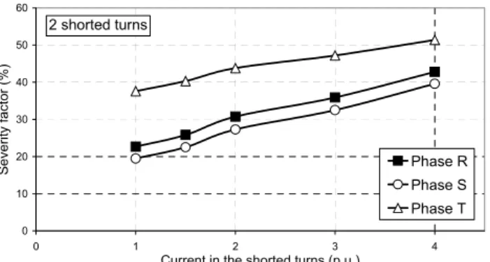
Fig. 9 presents the evolution of the severity factor, given by (7), with the current in the two shorted turns. The values of the severity factor increase monotonically with the increase of the faulty current [13]. However, as shown in the figure, the severity factor for the case of winding defect
(a)
(b)
(c) Figure 8. EPVA signature for the case of two shorted turns in the primary
winding of phase R, with the following values of faulty current: (a) In; (b) 2×In; (c) 4×In.
(a) (b) (c)
Figure 7.: Simulated on-load exciting current Park's Vector patterns for the case a YNyn0 connection, rated load condition and two shorted turns in the primary winding, with several values of faulty current (in terms of the rated current of the affected winding, In), and for different faulty phases:
Advanced Research Workshop on Modern Transformers. ARWtr 2004 28 -30 October 2004. Vigo – Spain 0 10 20 30 40 50 60 70 0 11 22 33
Number of shorted turns
S eve rit y f act or (% ) Phase R Phase S Phase T Faulty current = rated current 0 10 20 30 40 50 60 0 1 2 3 4
Current in the shorted turns (p.u.)
Se ve ri ty fa ct or ( % ) Phase R Phase S Phase T 2 shorted turns 0 10 20 30 40 50 60 70 0 11 22 33
Number of shorted turns
Sever ity factor (%) Phase R Phase S Phase T Faulty current = rated current
in phase T has higher values as compared to the other phases, for the same type of fault. This is a consequence of the normal asymmetry of the transformer's magnetic circuit, which leads to the natural deformation of the on-load exciting current Park's Vector pattern and to the presence of the residual 2f spectral component in the EPVA signature, under healthy operating conditions. When a fault occurs in the winding of phase T, the natural asymmetry reinforces the severity of the fault, as can be seen by the on-load exciting current Park's Vector patterns of Fig. 7(c), resulting into higher values of the severity factor, as compared to the other phases. This aspect must be taken into consideration when the proposed diagnostic technique is applied, by comparing the on-load exciting current Park's Vector pattern with the EPVA signature: the first gives the information about the faulty phase and the second gives the value of the severity factor.
The results clearly indicate that the proposed diagnostic technique is sensitive to low level faults.
In the experimental setup only medium/heavy severity fault tests can be performed. Fig. 10 shows the evolution of the severity factor with the number of shorted turns. Similar conclusions to the ones presented for the case of incipient faults can be drawn. It can be also seen that the severity factors of the 3 phases converge to the same value for large insulation defects (33 shorted turns). In these conditions the natural asymmetry of the transformer's magnetic circuit is no longer relevant in the EPVA signature. The corresponding simulated results are presented in Fig. 11, which are in close agreement with the experimental ones.
The severity factor is independent of the transformer's load conditions, since its computation is based on the on-load exciting currents, which are unaffected by the load level. Other experimental and simulated tests carried out for different types of the transformer windings connection, fault location and load conditions lead to similar conclusions to the ones presented before [11], [12], [15].
IV. CONCLUSIONS
This paper presents the application of the on-load exciting current Extended Park's Vector Approach for diagnosing the occurrence of inter-turn short-circuits in the windings of operating three-phase transformers, which consists in the spectral analysis of the AC level of the on-load exciting current Park's Vector modulus. The proposed on-line diagnostic technique combines the advantages of three well known methods:
o the former Park's Vector Approach, which assemble the three-phase system in only one quantity;
o the on-load exciting current, which enhances the severity of the fault, giving an increased sensitivity about the condition of the transformer;
o the spectral analysis, which gives a more detailed
Figure 9. Evolution of the severity factor with the current in the two shorted turns (simulated results).
Figure 10. Evolution of the severity factor with the number of shorted turns (experimental results).
Figure 11. Evolution of the severity factor with the number of shorted turns (simulated results).
insight into the results obtained by the Park's Vector [13].
Experimental and/or simulated test results were presented, which demonstrate the effectiveness of the diagnostic technique.
Further work is currently in progress, concerning the refinement of the proposed diagnostic technique, with the aim of dealing with winding intermittent faults and three--winding transformers. Also, on-site tests are currently being conducted, in order to assess the behaviour of the diagnostic method in a real industrial environment.
Advanced Research Workshop on Modern Transformers. ARWtr 2004 28 -30 October 2004. Vigo – Spain
REFERENCES
[1] Wang, M. - A Novel Extension Method for Transformer
Fault Diagnosis - IEEE Transactions on Power Delivery,
vol. 18, No. 1, pp. 164-169, January 2003.
[2] IEEE Std. C37.91-2000 – IEEE Guide for Protective
Relay Applications to Power Transformers – IEEE 2000.
[3] Barkan, P.; Damsky, B. L.; Ettlinger, L. F. and Kotski, E. J. – Overpressure Phenomena in Distribution
Transformers With Low Impedance Faults: Experiment and Theory – IEEE Transactions on Power Apparatus and
Systems, vol. 95, No. 1, pp. 37-48, January/February 1976.
[4] Stigant, S. A. and Franklin, A. C. – The J&P Transformer
Book – 10th Edition, Newnes Butterworths, London,
1973.
[5] González, G. D.; Férnandez, J. G. A. and Arboleya, P. A. – Diagnosis of a Turn-To-Turn Short Circuit in Power
Transformers by Means of Zero Sequence Current Analysis – Electric Power Systems Research, vol. 69, pp.
321-329, 2004.
[6] Raux, C.; Leconte, C. and Gibert, T. – Resistance of
Transformers to Internal Faults: Synthesis of Experimental Results – 10th International Conference on
Electricity Distribution (CIRED 1989), pp. 71-75, May 1989.
[7] Plummer, C. W.; Goedde, G. L.; Petit, E. L.; Godbee, J. S. and Hennessey, M. G. – Reduction in Distribution
Transformer Failures Rates and Nuisance Outages Using Improved Lightning Protection Concepts – IEEE
Transactions on Power Delivery, vol. 10, No. 2, pp. 768-777, April 1995.
[8] Lunsford, J. M. and Tobin, T. J. – Detection of and
Protection for Internal Low-Current Winding Faults in Overhead Distribution Transformers – IEEE Transactions
on Power Delivery, vol. 12, No. 3, pp. 1241-1249, July 1997.
[9] Cardoso, A. J. M. – The Park's Vector Approach: a
General Tool for Diagnostics of Electrical Machines, Power Electronics and Adjustable Speed Drives – Record
of the 1997 IEEE International Symposium on Diagnostics for Electrical Machines, Power Electronics and Drives, Carry-le-Rouet, France, pp. 261-269, 1997. [10] Cardoso, A. J. M. and Oliveira, L. M. R. – Condition
Monitoring and Diagnostics of Power Transformers –
International Journal of COMADEM, vol. 2, No. 3, pp. 5-11, July 1999.
[11] Oliveira, L. M. R.; Cardoso, A. J. M. and Cruz, S. M. A. – Transformers On-Load Exciting Current Park's Vector
Approach as a Tool for Winding Faults Diagnostics –
Conference Record of the 15th International Conference on Electrical Machines (ICEM 2002), CD-ROM, 6 pp., Brugge, Belgium, August 2002.
[12] Oliveira, L. M. R. – Development and Implementation of
a Digital Model for Transformer Winding Fault Studies – An Introduction to a New Diagnostic Method – (in
Portuguese), M.Sc. thesis, University of Coimbra, Portugal, 2001.
[13] Cruz, S. M. A. and Cardoso, A. J. M. – Stator Winding
Fault Diagnosis in Three-Phase Synchronous and Asynchronous Motors, by the Extended Park's Vector Approach – IEEE Transactions on Industry Applications,
vol. 37, No. 5, pp. 1227-1233, September/October 2001. [14] Oliveira, L. M. R. and Cardoso, A. J. M. – Three-Phase,
Three-Limb, Steady-State Transformer Model: the Case of a Ynzn Connection – Proceedings of the IASTED
International Conference, "Power and Energy Systems", pp. 467-472, September 2000.
[15] Oliveira, L. M. R. and Cardoso, A. J. M – On-Line
Diagnostics of Transformer Winding Insulation Failures, by Park's Vector Approach – Proceedings of the 9th
International Electrical Insulation Conference (INSUCON 2002), pp 16-21, Berlin, Germany, June 2002.
[16] Oliveira, L. M. R. and Cardoso, A. J. M. – Parameters
Determination for the Coupled Electromagnetic Transformer Model, With Particular Reference to Winding Faults Studies – (in Portuguese), 8º Congresso
Luso Espanhol de Engenharia Electrotécnica (8 CLEEE), vol. III, pp 6.333-6.338, Vilamoura, Portugal, July 2003.