Fiabilitate si Durabilitate - Fiability & Durability Supplement No 1/ 2014 Editura “Academica Brâncuşi” , Târgu Jiu, ISSN 1844 – 640X 182
CONSIDERATIONS FOR THE DEVELOPMENT OF A DEVICE FOR THE
DECOMMISSIONING OF THE HORIZONTAL FUEL CHANNELS IN
THE CANDU 6 NUCLEAR REACTOR
PART 4 - FUEL CHANNEL ASSEMBLY
FIZ. DRD. Gabi ROSCA FARTAT e-mail: [email protected]
PROF. UNIV. EMERIT DR. ING. Constantin D. STANESCU e-mail: [email protected]
ING. Constantin POPESCU Polytechnic University of Bucharest
ABSTRACT: As many nuclear power plants are reaching their end of lifecycle, the decommissioning of these
installations has become one of the 21st century’s great challenges. Each project may be managed differently,
depending on the country, development policies, financial considerations, and the availability of qualified engineers or specialized companies to handle such projects. The principle objective of decommissioning is to place a facility into such a condition that there is no unacceptable risk from the decommissioned facility to public health and safety of the environment. In order to ensure that at the end of its life the risk from a facility is within acceptable bounds, action is normally required. The overall decommissioning strategy is to deliver a timely, cost-effective program while maintaining high standards of safety, security and environmental protection. If facilities were not decommissioned, they could degrade and potentially present an environmental radiological hazard in the future. Simply abandoning or leaving a facility after ceasing operations is not considered to be an acceptable alternative to decommissioning. The final aim of decommissioning is to recover the geographic site to its original condition.
Key words: Candu reactor, calandria tube, fuel channel, pressure tube, fuel bundle, end fitting, feeder coupling, annulus spacer, positioning assembly, annulus bellows, shield plugs, channel closures.
1. INTRODUCTION
The install operations to a new fuel channel within a calandria CANDU reactor, must to comply the described requirements in the specified documents by AECL.
The required specifications of the install operations to a new fuel channel are defined by: - fuel channel installation requirements;
- the general requirements for tools and equipments;
- for welding procedures for structural welding of sealing rings; - the quality assurance program.
Before installing a new component in the fuel channel, checks should be made of existing parts into the canal, to observe there are in correct position or if there is non-compliance. Before installation is performed the cleaning and inspection of the component will be installed and where they will be mounted.
Fiabilitate si Durabilitate - Fiability & Durability Supplement No 1/ 2014 Editura “Academica Brâncuşi” , Târgu Jiu, ISSN 1844 – 640X 183
2. FUEL CHANNEL COMPONENTS ASSEMBLY STEPS
2.1. General considerations
Installation of each component is performed according to the design documentation and detailed diagram of a fuel channel from CANDU nuclear reactors composition is presented in Figure 1.
Fig. 1 - Schematic representation of the component parts of the CANDU fuel channel
The component parts of CANDU fuel channel are:
Fiabilitate si Durabilitate - Fiability & Durability Supplement No 1/ 2014 Editura “Academica Brâncuşi” , Târgu Jiu, ISSN 1844 – 640X 184
2.2. Initial conditions
The fuel channel components assembly is performed when the following components are pre-assembled (Figure 2):
- calandria tube (10) is mounted with crimping rings in calandria tubesheet (11);
- endshield lattice tube (15) is also mounted and fixed between the calandria tubesheet (11) and fuelling tubesheet (16);
- the space between the calandria tubesheet (11) and fuelling tubesheet (16) is filled with endshield shielding balls (14).
Fig. 2 - Schematic representation of fuel channel pre-assembled components
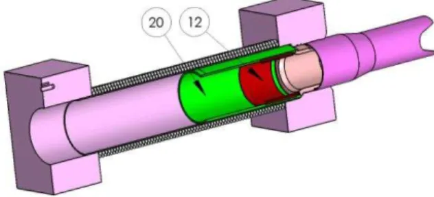
2.3. Lattice tube shielding sleeve mounting
The operations of this procedure are the following (Figure 3):
- defects inspection, lattice tube shielding sleeve dimension check and body cleaning, defects inspection, inboard bearings dimension check and cleaning it before installation; if, after inspection and verification operations; if they correspond, proceed to the next step;
- insert the shielding sleeve (20) into endshield lattice tube (15) up to the crimping ring for calandria tube (10) fixed to the calandria tubesheet.
- insert the inboard bearings (12) in the shielding sleeve (20) and fixing it in the end from of calandria.
- after each operation, the resulting information must be recorded in the specific registration and verification documents of each component and each operation.
Fiabilitate si Durabilitate - Fiability & Durability Supplement No 1/ 2014 Editura “Academica Brâncuşi” , Târgu Jiu, ISSN 1844 – 640X 185
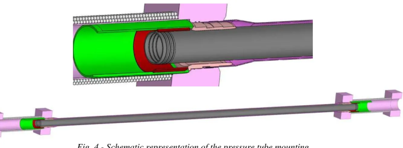
2.4. Pressure tube mounting
Pressure tube (9) mounting is carried out after the assembly and fixation of the lattice tube shielding sleeve in lattice tube (Figure 4).
The operations of this procedure are the following:
- defects inspection, pressure tube and calandria tube dimension check and body cleaning before installation; after inspection and verification operations, if they correspond, proceed to the next step;
- platform moving to maintenance position for the pressure tube installation into the fuel channel pushing device; the pressure tube will be covered with a protective sleeve and will be mounted the calandria tube guide cones;
- movement of the platform in the fuel channel front position where the pressure tube will be mounted;
- pushing the pressure tube, inside the calandria tube until the established quota by working procedure;
Fig. 4 - Schematic representation of the pressure tube mounting
- after each operation, the resulting information shall be recorded in the specific registration and verification documents of each component and each operation.
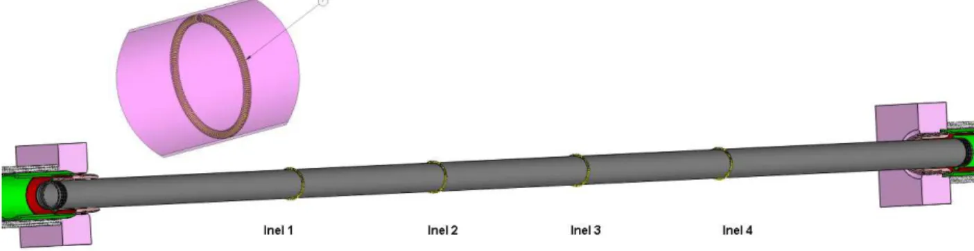
2.5. Annulus spacers mounting
In a fuel channel, is necessary to have a constant annular space maintained between the pressure tube and the calandria tube, to allow the gas circulation which provides thermal insulation of the pressure tube to relatively cold calandria tube. Therefore, the annulus spacers (7) have been used to maintain the space between the pressure tube and the calandria tube. They must be installed on the pressure tube after the tube has been placed inside calandria tube and secured at one end.
The operations for positioning of annulus spacers are the following:
Fiabilitate si Durabilitate - Fiability & Durability Supplement No 1/ 2014 Editura “Academica Brâncuşi” , Târgu Jiu, ISSN 1844 – 640X 186
- installing of annulus spacers is carried out as follows (Figure 5): are mounted two annulus spacers from the plane R, the pressure tube is blocked from the plane R, first spacer no. 2 then spacer no. 1 and the other two first spacer no.3 then spacer no. 4, from the plane R, the pressure tube is blocked from the plane R; the operation is carried out by the aid of a device for introducing onto the pressure tube and with the annulus closing positioned at the bottom;
Fig. 5 - Schematic representation of the annulus spacers mounting
- after each installation, the position of each annulus spacing, shall be recorded in the specific registration and verification documents of each component and each operation.
2.6. End fitting pre-assembly
End fittings and related accessories are assembled before their introduction into the fuel channel.
The operations of this procedure are the following:
- end fitting selection and placing it on the workbench (Figure 6);
Fig. 6 - Schematic representation of the end fitting
- inspection for defects, end fitting dimension check, feeder holes and threads check and end fitting cleaning; end fitting components inspection for defects, dimension check and components cleaning that will be installed at the end fitting, if they correspond go to next step;
Fiabilitate si Durabilitate - Fiability & Durability Supplement No 1/ 2014 Editura “Academica Brâncuşi” , Târgu Jiu, ISSN 1844 – 640X 187
Fig. 7 - Schematic representation of the inner ring seal mounting
- shall be mounted the outboard bearing (6) then, in extension, the end fitting shielding sleeve (19); the shielding sleeve is secured by a elastic safety lock (23) (Figure 8);
Fig. 8 - Schematic representation of the outboard bearing and the shielding sleeve mounting
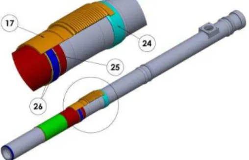
- the end fitting is welded on the support ring (24) for mounting of channel annulus bellows isolation (17) (Figure 9);
Fig. 9 - Schematic representation of the support ring for channel annulus bellows isolation mounting
- inside of the channel annulus bellows (17), into channel side, is mounted the annulus bellows outer ring seal (25) which is secured against movement by two elastic safety locks (26);
- shall be mounted the channel annulus bellows (17) on the end fitting over the annulus bellows outer ring seal (25) and the outer end is welded on the support ring (24) (Figure 10);
Fig. 10 - Schematic representation of the channel annulus bellows mounting
Fiabilitate si Durabilitate - Fiability & Durability Supplement No 1/ 2014 Editura “Academica Brâncuşi” , Târgu Jiu, ISSN 1844 – 640X 188
- after testing, the end fitting it clean up and wiped; shall be mounted plugs at both ends to prevent ingress of dirt inside; shall be stored in dry and clean atmosphere before installation; - after each operation, the resulting information shall be recorded in the specific registration and verification documents of each component and each operation.
2.7. End fitting mounting into the fuel channel
The fitting end shall be mounted into the fuel channel provided that the pressure tube is fixed and blocked to the other end to prevent the displacement at the time of the end fitting introduction into fuel channel for mounting.
The operations of end fitting mounting into fuel channel are the following:
- selection, inspection for defects, checking for dimension and final cleaning of end fitting before mounting in relation to the selected channel; after inspection and verification operations, if they correspond, proceed to the next step;
- moving the platform in maintenance position for installing of the end fitting into the introduction device in the fuel channel; the end fitting will be positioned into the introduction device relative to the channel position where will be introduced, that is, no. area, line, column, front or rear calandria zone, so the end fitting mounting position relative to the feeder coupling position (3) to be 0 °, left 32 °, 58 °, 90 ° , right 32 °, 58 °, 90 ° (Figure 11); the end fitting will be covered with an protection sleeve against possible impurities;
32º±30´ 58º±30´
90º±30´ 0º±30´ 32º±30´ 90º±30´
Zone 1 Zone 2 Zone 3 Zone 4 Zone 5 Zone 6 Zone 7
58º±30´
Fig. 11 - Schematic representation of the end fitting orientation for the feeder coupling
- platform moving to the fuel channel front position where the end fitting will be inserted;
- end fitting introducing command inside calandria up to established position from working procedure; the end fitting is inserted into the lattice tube shielding sleeve (20), taking care to be maintained the fitting horizontality; also should be considered that inside fitting, has to enter the pressure tube was centered in advance (Figure 12);
Fiabilitate si Durabilitate - Fiability & Durability Supplement No 1/ 2014 Editura “Academica Brâncuşi” , Târgu Jiu, ISSN 1844 – 640X 189
- inside the end fitting shall be inserted the crimping head (rolling) up to the beginning of pressure tube (10); the pressure tube is rolled inside the fitting on the inside of the end fiting, positions determined by the working procedure (Figure 13);
Fig. 13 - Schematic representation of the pressure tube crimping on the inside of end fitting
- the liner tube (4) shall be inserted into the end fitting using by the introduction device by cold pressing, up to the end of the pressure tube (9) rolled inside the end fitting (Figure 14);
Fig. 14 - Schematic representation of the liner tube mounting inside of end fitting
- in the outer end of end fitting is mounted one elastic safety lock (2) (Figure 15);
Fig. 15 - Schematic representation of the elastic safety lock mounting inside of end fitting
Fiabilitate si Durabilitate - Fiability & Durability Supplement No 1/ 2014 Editura “Academica Brâncuşi” , Târgu Jiu, ISSN 1844 – 640X 190
Fig. 16 - Schematic representation of the shield plug mounting inside of end fitting
- the channel closure (1) shall be inserted in the head of introduction device; the channel closure is unlocks to be inserted into the end fitting; the channel closure is unlocks to be inserted into the end fitting; the device shall be inserted into the end fitting up to the position where the closure locks are inside the groove of the end fitting; the channel closure is blocked by decoupling the introduction device (Figure 17);
Fig. 16 - Schematic representation of the channel closure mounting inside of end fitting
Fiabilitate si Durabilitate - Fiability & Durability Supplement No 1/ 2014 Editura “Academica Brâncuşi” , Târgu Jiu, ISSN 1844 – 640X 191
Fig. 18 - Schematic representation of the feeder coupling mounting at the end fitting
- after each operation, the resulting information shall be recorded in the specific registration and verification documents of each component and each operation.
2.8. Positioning assembly mounting
The positioning assembly is mounted on the end fitting provided that the end fitting is mounted in the fuel channel and adjustments can be made according to the working procedures.
The operations of positioning assembly mounting on fuel channel are the following: - positioning assembly selection in relation to the selected channel for installation, inspection for defects, checking for dimension and final cleaning for installation; after inspection and
verification operations, if they correspond, proceed to the next step;
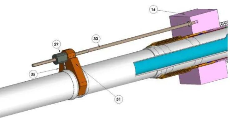
- in the threaded part (29) shall be inserted the rod positioning (30) (Fig. 19);
Fig. 19 - Schematic representation of the rod positioning mounting
Fiabilitate si Durabilitate - Fiability & Durability Supplement No 1/ 2014 Editura “Academica Brâncuşi” , Târgu Jiu, ISSN 1844 – 640X 192
Fig. 20 - Schematic representation of the clamping and fastening pieces mounting for the rod positioning
- after rod positioning (30) is screwed, are mounted, on the left and right side of the clamping and fastening pieces (31), the two safety lock for counter nut (33), spring plate type, fastened with screws (Fig. 21);
Fig. 21 - Schematic representation of the safety lock for counter nut mounting
- the two safety lock (33) are maintained spread apart and on the positioning rod (30) is mounted the counter nut locking (32); that is tightened up to the mentioned quota in the mounting
Fiabilitate si Durabilitate - Fiability & Durability Supplement No 1/ 2014 Editura “Academica Brâncuşi” , Târgu Jiu, ISSN 1844 – 640X 193
Fig. 22 - Schematic representation of counter nut locking mounting and blocking
- upon completion of the rod positioning (30), in the calandria fuelling tubesheet (16) is made a hole for the lock pin; the lock pin shall (34) be inserted into the recess of the rod positioning (Figure 23);
Fig. 23 - Schematic representation of lock pin mounting for rod positioning
- after each operation, the resulting information shall be recorded in the specific registration and verification documents of each component and each operation.
3. CONCLUSIONS
The fuel channels from CANDU nuclear reactors, using the pressure tubes with thin-walled of zirconium alloy, are the most important part of the calandria and designed to resist to the cooling fluid flow, temperature, pressure and imposed conditions by the of the heat transport system.
Fiabilitate si Durabilitate - Fiability & Durability Supplement No 1/ 2014 Editura “Academica Brâncuşi” , Târgu Jiu, ISSN 1844 – 640X 194
Registration documents, checking documents and reports relating to the required
operations of fuel channel installation will be archived to have any time a sequentially image of each fuel channel.
Fuel channels have a large contribution for the operation of CANDU reactors because they allow new refueling while operating at full capacity.
REFERENCES
[1] CHEADLE B.A., PRICE E.G., "Operating performance of CANDU pressure tubes", presented at IAEA Techn. Comm. Mtg on the Exchange of Operational Safety Experience of Heavy Water Reactors, Vienna, 1989;
[2] ROGER G. STEED, "Nuclear Power in Canada and Beyond", Ontario, Canada, 2003; [3] VENKATAPATHI, S., MEHMI, A., WONG, H., "Pressure tube to end fitting roll
expanded joints in CANDU PHWRS", presented at Int. Conf. on Expanded and Rolled Joint Technology, Toronto, Canada, 1993;
[4] AECL, "CANDU Nuclear Generating Station", Engineering Company, Canada; [5] AECB, "Fundamentals of Power Reactors", Training Center, Canada;
[6] CANDU, "EC6 Enhanced CANDU 6 - Technical Summary", 1003/05.2012;
[7] CNCAN, "Law no. 111/1996 on the safe deployment, regulation, authorisation and control of nuclear activities", 1996;
[8] CNCAN, "Rules for the decommissioning of objectives and nuclear installations", 2002; [9] IAEA, “Assessment and management of ageing of major nuclear power plant
components important to safety: CANDU pressure tube”, IAEA-TEDOC-1037, Vienna 1998;
[10] IAEA, “Nuclear Power Plant Design Characteristics, Structure of Power Plant Design Characteristics in the IAEA Power Reactor Information System (PRIS)”, IAEA-TECDOC-1544, Vienna 2007;
[11] IAEA, “Water channel reactor fuels and fuel channels: Design, performance, research
and development”, IAEA-TEDOC-997, Vienna 1996;
[12] IAEA, “Assessment and management of ageing of major nuclear power plant
components important to safety: CANDU reactor assemblies”, IAEA-TEDOC-1197,
Vienna 2001;
[13] IAEA, “Heavy Water Reactor: Status and Projected Development”, IAEA-TEREP-407, Vienna 1996;
[14] Nuclearelectrica SA, "Cernavoda NPP Unit 1&2, Safety features of Candu 6 design and stress test summary report", 2012;