Fiabilitate si Durabilitate - Fiability & Durability Supplement No 1/ 2014
Editura “Academica Brâncuşi” , Târgu Jiu, ISSN 1844 – 640X
173
CONSIDERATIONS FOR THE DEVELOPMENT OF A DEVICE FOR THE
DECOMMISSIONING OF THE HORIZONTAL FUEL CHANNELS IN
THE CANDU 6 NUCLEAR REACTOR
PART 3 - FUEL CHANNEL REFERENCES
FIZ. DRD. Gabi ROSCA FARTAT
e-mail: [email protected]
PROF. UNIV. EMERIT DR. ING. Constantin D. STANESCU
e-mail: [email protected]
ING. Constantin POPESCU
Polytechnic University of Bucharest
Abstract: As many nuclear power plants are reaching their end of lifecycle, the decommissioning of these
installations has become one of the 21st century’s great challenges. Each project may be managed differently, depending on the country, development policies, financial considerations, and the availability of qualified engineers or specialized companies to handle such projects.
The principle objective of decommissioning is to place a facility into such a condition that there is no unacceptable risk from the decommissioned facility to public health and safety of the environment. In order to ensure that at the end of its life the risk from a facility is within acceptable bounds, action is normally required.
The overall decommissioning strategy is to deliver a timely, cost-effective program while maintaining high standards of safety, security and environmental protection. If facilities were not decommissioned, they could degrade and potentially present an environmental radiological hazard in the future. Simply abandoning or leaving a facility after ceasing operations is not considered to be an acceptable alternative to decommissioning.
The final aim of decommissioning is to recover the geographic site to its original condition.
Key words: Candu reactor, calandria tube, fuel channel, pressure tube, fuel bundle, end fitting,
1. INTRODUCTION
Nuclear reactors are designed and built so as to comply the specific requirements of codes and standards for the manufacture of components, equipment and systems necessary for construction and operation of CANDU nuclear power.
Reactor assembly consists a hollow cylindrical structure called the calandria assembly, fuel channels and control mechanisms of reactivity.
Fuel channels, the number of 380, pressure tubes made of zirconium-niobium alloy, located inside the calandria tubes, chuck in end fitting that are supported by the pipes network of the supply feeders.
Fiabilitate si Durabilitate - Fiability & Durability Supplement No 1/ 2014
Editura “Academica Brâncuşi” , Târgu Jiu, ISSN 1844 – 640X
174
2. CONDITIONS TO IMPOSE ON REQUIRED MATERIALS FOR FUEL CHANNELS
2.1. General considerations on zirconium alloys
Because of nuclear, physical, chemical properties, excellent refractory, good mechanical resistance, zirconium has become one of the main materials for the nuclear industry. By alloying with tin, iron, chromium, nickel, niobium, aluminium, molybdenum, zirconium alloys provides a full range of zircaloy known. It shows better resistance, is ductile, corrosion resistant and has nuclear properties close to pure zirconium.
Used industrial Zirconium can achieve the required purity to have resistance corrosion and satisfying mechanical properties. If you do not take special precautions, in the zirconium process obtaining, in the material are introduced a number of impurities, the most damaging being gases (oxygen, nitrogen, hydrogen) and carbon. Nitrogen and carbon reduce corrosion resistance, hydrogen makes it fragile and oxygen hardens the zirconium, so that it becomes difficult to process. Carbon and hydrogen contamination can be prevented by special measures being taken during surgery to obtain and processing the material. To combat all undesirable effects should be used in Zirconium alloying. By alloying with tin, iron, chromium and nickel are obtained zirconium alloys known as zircaloy (Table 1.1). They have a significantly better corrosion resistance.
Table 1.1 - Chemical composition of zirconium alloys
Alloy Content of alloying elements (%)
Sn Fe Cr Ni Nb
Zircaloy – 2 1,5 0,14 0,1 0,06 -
Zircaloy – 3 0.25 0,25 0,05 0,05 -
Zircaloy – 4 1,5 0,17 0,12 - -
Ozenit 0,25 0,1 - 0,1 0,1
Some of zirconium alloys properties are presented in Table 1.2.
Table 1.2 - Some zirconium alloys properties
Material Temperature [0C] Tear resistance [ Mpa] Flow resistance [MPa]
Annealed pure Zr 25 260 354 171 110 65
Zircaloy – 2 25 250
1180 868
915 559 Zircaloy – 3 25
260
907 422
Fiabilitate si Durabilitate - Fiability & Durability Supplement No 1/ 2014
Editura “Academica Brâncuşi” , Târgu Jiu, ISSN 1844 – 640X
175
The presented values in this table are strictly indicative, because mechanical properties of zirconium and its alloys depend greatly on how manufacturing mode. Another zirconium alloys category consists the alloys niobium (1% or 2% by weight). These are better mechanical properties and corrosion resistance than zircaloy-2, especially at high temperatures.
The irradiation effects on zirconium and its alloys is reflected in macroscopic scale by altering their mechanical properties as a result of the action of fast neutrons and the material weakening due to the hydrogen absorption and its precipitation in the form of zirconium hydride. Following fast neutrons interaction (E> 1 MeV) with zirconium and its alloys are produced defects clusters and loops dislocations, whose size and mass distribution in the material depends on integrated neutron flux, irradiation temperature and material composition.
Another effect of the fast neutrons interaction with zirconium and its alloys consists in size modifying and their original shape. Zirconium and its alloys have a crystal structure of hexagonal compact type, which favors unequal storage of prismatic and basal plane of holidays and interstitial atoms generated by the interaction of fast neutrons.
Any defects of irradiation induced, which remains isolated in the network, is reflected in dimensional parameters variations in macroscopic scale, namely in volume change and shape of the material.
The above mentioned materials are used in the non-nuclear manufacture of: - heat exchangers (manufacture of acetic acid, sulphuric acids, and organic acids)
- stripping and drying column for the acetic acid industry, sulphuric acid and organic acids - reaction vessels and tanks for corrosive environments
- piping in ethyl-benzene reactors
- pumps and valves for corrosive environments and in the nuclear field:
- fuel sheaths - fuel bundles - pressure tubes - calandria tubes
- assembly and strength parts.
2.2. Necessary materials for pressure tubes manufacturing
For pressure tubes are set to work an alloy of Zr-2.5% Nb which is cold worked. According to the Canadian standards requirements, the zirconium alloy processing is seamless to the fuel channel assembly.
Fiabilitate si Durabilitate - Fiability & Durability Supplement No 1/ 2014
Editura “Academica Brâncuşi” , Târgu Jiu, ISSN 1844 – 640X
176
2.3. Necessary materials for calandria tubes manufacturing
Calandria tubes are part of the pressure circuit moderator. Calandria tube is a class 3, which is designed at a 70-85 kPa pressure and a 100° C temperature. The normal operating temperature is 85° C.
Calandria tubes are zircaloy 2-rolled strip made, rolled and welded to tube format. In normal operation the tubes are subjected to very high neutron flux, so by their zirconium alloy making, is not required to their replace on the designed lifetime reactor.
2.4. Necessary materials for end fittings manufacturing
The mounted component material for pressure tube joining is required to resist on rolling forces, residual stresses and leak tightness. Resistance and corrosion requirements are satisfied by stainless steel 304 type. So that, the component limitations of chemical composition are made by main alloying elements weightings, such as carbon and chromium, which are limited to reduce rupture vulnerability, the impact properties and the allowable limits of residues element such as phosphorus, sulphur and copper, which are in small quantities to improve resistance to corrosion and irradiation. The cobalt use is limited for reasons activities, it can easily become radioactive.
3. FUEL CHANNEL INSTALLATION STEPS
3.1. Reference planes definition
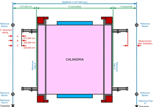
Defining of Calandria reference plans are carried out between R and R' plans. That is defined as reference planes for front and rear part of the calandria (Figure 1).
The operations for plans determination are as follows: - preliminary determination of the R plan;
- preliminary determination of the R' plan;
- establishing of the R plane reference and markers reference;
- distance determining between P and P' planes reference, front and back calandria planes; - establishing of the R' plane reference and markers reference.
Fiabilitate si Durabilitate - Fiability & Durability Supplement No 1/ 2014
Editura “Academica Brâncuşi” , Târgu Jiu, ISSN 1844 – 640X
177
CALANDRIA
Theodolite
Reference Plan R
Theodolite
Reference Plan
R’
X (calculated) Y (measured)
NOMINAL (11277,800 mm)
Measurement after installation
R
e
fere
n
ce
Pl
an
P’
R
e
fe
re
nce
Pl
an
P
E.F. dimension setting
Reference Marker
1727,200 mm
228,600 mm C
B A
220,980 mm 213,360 mm
Reference Marker Reference
Marker Reference
Marker
Fig. 1 - Schematic representation of the reference plans for measurements making at fuel channel installation
3.2. Fuel channels measurements reported to the reference plane
Registration document of reference planes measurements contains entries for: used instruments to measurements, measured temperatures at different calandria points; measurements to the R and to R' reference plane; A, B, C and A', B', C' distances measuring to the R and to R' reference planes; calandria X distances measuring between P and P' plane; Y distance measurement between the P' plane reference and the R' plane reference.
Record document of measurements for fuel channel length calculation provides three fuel channels category:
- A channel category - nominal length of 10,850 mm; - B channel category - nominal length of 10 836 mm; - C channel category - nominal length of 10,820 mm;
Recording document of distances measurement from the plane R or R' to end fitting for fuel channel type is prepared to:
- R-A / R'-A' = 213,36 mm; - R-B / R'-B' = 220,98 mm; - R-C / R'-C' = 228,60 mm.
Fiabilitate si Durabilitate - Fiability & Durability Supplement No 1/ 2014
Editura “Academica Brâncuşi” , Târgu Jiu, ISSN 1844 – 640X
178
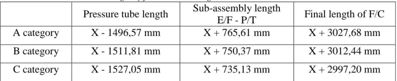
Table 1 - the elements channel length by fuel channels categories
Pressure tube length Sub-assembly length
E/F - P/T Final length of F/C A category X - 1496,57 mm X + 765,61 mm X + 3027,68 mm B category X - 1511,81 mm X + 750,37 mm X + 3012,44 mm C category X - 1527,05 mm X + 735,13 mm X + 2997,20 mm
General registration document for fuel channel installing contains entries for: pressure tube, outer diameter and thickness, end fitting, series no. , color, common bore diameter roller, calculated and final; power feeder angle, calculated and final; gap between pressure tube and the liner tube before and after the rolling phase; the total length of the final sub-assembly; the distance between end fitting E / F and the reference plane before and after rolling; the final overall length of the fuel channel; the data relating to test calibration; the data relating to pressure; welds checking and identifying; identification bulletin control; welder identification.
General registration document and identification of each fuel channel in report of the calandria aria contains entries for: aria no., the end fitting serial number from R plane, the end fitting serial number from R' plane, the identification code of the pressure tube.
Registration document and identification of the assembly, LP (penetrant liquid) control of ring gas sealing tube in each fuel channel contains entries for: the ring gas sealing tube area, 103.4 kPa pressure test; test time.
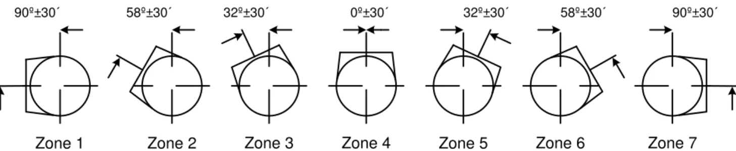
Registration document and identification of the mounting position and the end fitting orientation to the end of each fuel channel contains entries for: area no. (Figure 2), line, column and front or rear of calandria, input / output feeder type, mounting position of the end fitting at 0°, left 32°, 58°, 90°, 32° right, 58° and 90° (Figure 3).
A A
A A A A
B A D C F E H G K J M L O N Q P S R U T W V
22 21 20 19 18 17 16 15 14 13 12 11 10 9 8 7 6 5 4 3 2 1
A
A A B B B B B B A A A
B
A B B C C C C C C B B B A
C
C C C C C C C C C C C B A
A B
C
C C C C C C C C C C C B A
C C
A B
C
C C C C C C C C C C B A
A B C C C
C
C C C C C C C C C C C B A
C C
C C
A B
C
C C C C C C C C C C B A
A B C C C C C
C
C C C C C C C C C C C C C
C C
C C
A B B A
C
C C C C C C C C C C C C B
C C
C C
B C A
A
C
C C C C C C C C C C C C C
C C
C C
A B B A
C
C C C C C C C C C C C C B
C C
C C
B C A
A
C
C C C C C C C C C C C C C
C C
C C
A B B A
C
C C C C C C C C C C C C B
C C
C C
B C A
A
C
C C C C C C C C C C C B A
C C
C C
A B
C
C C C C C C C C C C B A
A B C C C C C
C
C C C C C C C C C C C B A
C C
A B
C
C C C C C C C C C C B A
A B C C C
C
C C C C C C C C C C B A
A B C
B
B B B C C C C C B B B A
A
B
A A A A
A B B B B B A
A A
A A A
A Zone 6 Zone 7 Zone 5 Zone 4 Zone 3 Zone 2 Zone 1
Fiabilitate si Durabilitate - Fiability & Durability Supplement No 1/ 2014
Editura “Academica Brâncuşi” , Târgu Jiu, ISSN 1844 – 640X
179
32º±30´ 58º±30´
90º±30´ 0º±30´ 32º±30´ 90º±30´
Zone 1 Zone 2 Zone 3 Zone 4 Zone 5 Zone 6 Zone 7
58º±30´
Fig. 3 - Schematic representation of end fitting orientation for the feeder pipe connection
Registration document and identification of the mounting position of the annulus spacers between pressure tube P/T and calandria tube C/T contains entries for: area no., line, column, the measured distance from the end fitting face, annulus spacer no.1 position, annulus spacer no.2 position, annulus spacer no.3 position, annulus spacer no.4 position (Figure 4).
Fig. 4 - Schematic representation of the annulus spacers position
3.3. Fuel channel installation operations
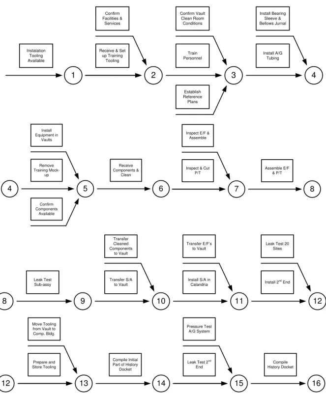
The install operations to a new fuel channel within a calandria CANDU reactor, must to comply the described requirements in the specified documents by AECL (Figure 5). Documents registration, verification documents and reports of the fuel channel installation are part of the processes register for assembly history of the nuclear reactor.
The required specifications of the install operations to a new fuel channel are defined by fuel channel installation requirements, the general requirements for tools and equipments, for welding procedures for structural welding of sealing rings, the quality assurance program.
General requirements and specifications in preparation for installing operations to a fuel channel are cleaning working areas and their temperature and humidity. All working areas where is performed fuel channel installation should be cleaned before entering the fuel channel components and equipment. At every operation, all components must be cleaned immediately, before use, with approved cleaning solvent. All tools that come in contact with reactor components must be initially cleaned with approved solvent and then whenever you need to keep them clean. All components , assembly areas and working areas should be monitored for the temperature to be in the range of 15-30º C. Recordings are made daily in the temperature registration document. Humidity in the working area must be at a level that temperature variations do not create condensation on equipment installation and reactor components.
Fiabilitate si Durabilitate - Fiability & Durability Supplement No 1/ 2014
Editura “Academica Brâncuşi” , Târgu Jiu, ISSN 1844 – 640X
180
Instalation Tooling Available
1
Receive & Set up Training Tooling 2 Confirm Facilities & Services Train Personnel 3 Confirm Vault Clean Room Conditions Establish Reference Plans Install A/G Tubing 4 Install Bearing Sleeve & Bellows Jurnal 4 Remove Training Mock-up 5 Install Equipment in Vaults Confirm Components Available Receive Components & Clean 6
Inspect & Cut P/T
7
Inspect E/F & Assemble Assemble E/F & P/T 8 8 Leak Test Sub-assy 9 Transfer S/A to Vault 10 Transfer Cleaned Components to Vault
Install S/A in Calandria Transfer E/F’s
to Vault
11
Install 2nd
End Leak Test 20
Sites 12 Prepare and Store Tooling 13 Move Tooling from Vault to Comp. Bldg.
Compile Initial Part of History
Docket
14
Leak Test 2nd
End 15 Pressure Test A/G System Compile History Docket 16 12
Fiabilitate si Durabilitate - Fiability & Durability Supplement No 1/ 2014
Editura “Academica Brâncuşi” , Târgu Jiu, ISSN 1844 – 640X
181
4. CONCLUSIONS
The fuel channels from CANDU nuclear reactors, which use thin-walled pressure tubes of zirconium alloy, are the most important part of the design of under pressure vessels working.
The install operations to a new fuel channel must comply with the described requirements from the specified documents by AECL. Documents registration, verification documents and reports of the fuel channel installation will be archived to take anytime a sequential picture of each fuel channel.
The fuel channels provide a large CANDU reactors contribution because they allow new refuelling while operating at full capacity.
REFERENCES
[1] CHEADLE B.A., PRICE E.G., "Operating performance of CANDU pressure tubes",
presented at IAEA Techn. Comm. Mtg on the Exchange of Operational Safety Experience of Heavy Water Reactors, Vienna, 1989;
[2] ROGER G. STEED, "Nuclear Power in Canada and Beyond", Ontario, Canada, 2003; [3] VENKATAPATHI, S., MEHMI, A., WONG, H., "Pressure tube to end fitting roll
expanded joints in CANDU PHWRS", presented at Int. Conf. on Expanded and Rolled
Joint Technology, Toronto, Canada, 1993;
[4] AECL, "CANDU Nuclear Generating Station", Engineering Company, Canada;
[5] AECB, "Fundamentals of Power Reactors", Training Center, Canada;
[6] CANDU, "EC6 Enhanced CANDU 6 - Technical Summary", 1003/05.2012;
[7] CNCAN, "Law no. 111/1996 on the safe deployment, regulation, authorisation and
control of nuclear activities", 1996;
[8] CNCAN, "Rules for the decommissioning of objectives and nuclear installations", 2002;
[9] IAEA, “Assessment and management of ageing of major nuclear power plant components important to safety: CANDU pressure tube”, IAEA-TEDOC-1037, Vienna 1998;
[10] IAEA, “Nuclear Power Plant Design Characteristics, Structure of Power Plant Design Characteristics in the IAEA Power Reactor Information System (PRIS)”, IAEA-TECDOC-1544, Vienna 2007;
[11] IAEA, “Water channel reactor fuels and fuel channels: Design, performance, research
and development”, IAEA-TEDOC-997, Vienna 1996;
[12] IAEA, “Assessment and management of ageing of major nuclear power plant components important to safety: CANDU reactor assemblies”, IAEA-TEDOC-1197, Vienna 2001;
[13] IAEA, “Heavy Water Reactor: Status and Projected Development”, IAEA-TEREP-407, Vienna 1996;
[14] Nuclearelectrica SA, "Cernavoda NPP Unit 1&2, Safety features of Candu 6 design and
stress test summary report", 2012;