Radosław Klimek
∗, Piotr Szwed
∗FORMAL ANALYSIS OF USE CASE DIAGRAMS
Use case diagrams play an important role in modeling with UML. Careful modeling is crucial in obtaining a correct and efficient system architecture. The paper refers to the formal analysis of the use case diagrams. A formal model of use cases is proposed and its construction for typical relationships between use cases is described. Two methods of formal analysis and verification are presented. The first one based on a states’ exploration represents a model checking approach. The second one refers to the symbolic reasoning using formal methods of temporal logic. Simple but representative example of the use case scenario verification is discussed.
Keywords: UML, use case, formal model, verification, model checking, temporal logic, se-mantic tableau
FORMALNA ANALIZA DIAGRAMÓW PRZYPADKÓW UŻYCIA
Diagramy przypadków użycia odgrywają znaczącą rolę w modelowaniu systemów z wykorzys-taniem UML. Staranne i dokładne modelowanie ma zasadnicze znaczenie w postępowaniu umożliwiającym uzyskanie poprawnej i efektywnej architektury systemu. Artykuł odnosi się do formalnej analizy diagramów przypadków użycia. Został zaproponowany model formal-ny przypadku użycia, a także opisano odpowiednie konstrukcje dla relacji występujących pomiędzy przypadkami użycia. Zostały przedstawione dwie formalne metody ich analizy i weryfikacji. Pierwsza oparta jest na eksploracji stanów i reprezentuje podejście nazwane weryfikacją modelową. Druga odwołuje się do wnioskowania symbolicznego z wykorzystaniem logiki temporalnej. Został pokazany prosty i reprezentatywny przykład weryfikacji pewnego scenariusza przypadku użycia.
Słowa kluczowe: UML, przypadek użycia, model formalny, weryfikacja, weryfikacja mode-lowa, logika temporalna, metoda tablic semantycznych
1. Introduction
Use cases are an important part of UML being a coherent story about system’s be-havior. They are used for documenting system requirements. They may also be used for communication both between various participants in a software project, i.e. sys-tem developers, its future users and owners. Test cases derived from use cases are
∗AGH University of Science and Technology, al. Mickiewicza 30, 30-059 Kraków, Poland,
{rklimek,pszwed}@agh.edu.pl
usually the criteria of a system acceptance. Use cases appear to be relatively easy-to-perception, even for people not familiar with the information technology. Use cases enable understanding the system though they do not fall too much in the implemen-tation details. On the other hand, errors committed in the course of the preparation of the use cases’ documentation may have far-reaching consequences, c.f. [12]. This may be manifested not only in the design phase of a well-balanced architecture of the system, but even in the implementation phase. Thus, the possibility of formal analysis of the diagrams can be an effective counterweight to the presented above threats. In addition, inference based on a formal approach allows the verification of the desired property of the modeled system. As the primary artifact of requirements documentation use cases appear in two complementary forms:
1. as graphical diagrams enumerating use cases and actors (usually users and ex-ternal systems) and showing relations between them;
2. as sets of scenarios describing from the actor’s perspective flows of events in the system.
Whereas the use case diagrams has strictly formalized syntax, several techniques could be used to document scenarios describing the system behavior. They include, for example, informal natural language, restricted natural language, Activity Diagrams or Message Sequence Charts.
The purpose of this paper is to present the possibility of formal analysis and verification of use cases of UML. This will be implemented in such a way that first a formal model of a use case is proposed. It includes a number of important elements and it’s creation is necessary because it can help to find a reliable basis for further discussion and formal verification. Construction methods for typical relationships be-tween use cases are presented, too. It seems obvious that the finite state machines is suitable as a semantic model for use cases, but there is a gap between natural lan-guage and finite state machines and the intention of this work is to provide a step in this direction.
The second purpose of this paper is to show the possibility of formal analysis of use cases. Use cases can also describe the system requirements and, therefore, formal verification of these requirements at the initial phase of the system modeling reduces production costs throughout the whole software development cycle. There are two basic methods that can be used for a formal use cases’ verification. The first one is based on a states’ exploration, i.e. the set of reachable states is determined and analyzed. This method represents a model checking approach. The second one refers to the symbolic reasoning using formal logic and the expressive language of temporal logic and the method of semantic tableau is used to prove system’s properties. It has been shown a common example to illustrate these two approaches. Model checking was discussed very thoroughly in this paper. Logical approach has been outlined here and in more detail shown in the paper [13].
on description of behavior between actors and use cases through the so-called contracts is presented. In work [19] a kind of a review technique for the use case diagrams is proposed. Work [16] contains the proposed division of scenarios, but it has no formal model and consequently there is a lack of reliable mechanism for formal reasoning about the modeled system. In work [4] consistency between use case scenarios and sequence diagrams is checked. Work [11] provides a very thorough and detailed survey of selected issues concerning use cases. The dualism of representations and informal character of scenarios documentation implies several difficulties in reasoning about the system behavior and validating the consistency between diagrams and scenarios description. Several research works in this field attempted to translate scenarios or formulate them in more formal language. Work [3] includes the transition of use cases to finite state machines, however the formal model presented in our work is more detailed and also shows the specific context of the formal verification. Work [20] shows the formal analysis of use cases, however, it has been used the Petri Nets formalism. The details of the models differed depending on the assumed purpose. They include relations with external objects from the class hierarchy [14], automatic generation of test cases [2], validation use cases against the regulatory constrains [18], tracking changes in use case based on FSM equivalence [3]. It should be mentioned, that in use case modeling methods has no systematic approach that would fully cover relations between use cases and reflect their presence in the models.
The rest of the paper has been organized as follows. First, the metamodel of the use case is be presented. The next step is to propose a formal model. Another point of work focuses on relationships occurring on the use case diagrams. The analyzed example is contained in a separate section. It includes a detailed and formal analysis using two different approaches mentioned above.
2. Metamodel
The use case diagram ([10, 7]) consists of actors and use cases. Actors are
environ-ment of the modeled system and use cases form this system.Actors are objects which
interacts with the target system.Use cases are services and functionalities which are
used by actors. Use cases should meet actors’ requirements. The use case diagram both identify external objects’ expectations for the system and specific features of the system. However, the diagram does not refer to the details of the system implemen-tation.
use case. Its occurrence depends on the satisfaction of certain conditions (extension points). Extending use cases can be treated as a set of alternative scenarios that was important enough to be transformed into stand alone use cases visible on the diagram and separately documented. The included use case must augment the execution of basic use case while the extended use case might be used to augment the execution.
Scenario
ScenarioSetp
StartPoint
Event Condition
ExtensionPoint
Guard
1
1 1
1
SetClause
1 0..* 1
*
UseCase
1
*
Variable
1 *
*
* *
* 1
*
SuccessPostCondition
1
* 1
*
*
*
*
*
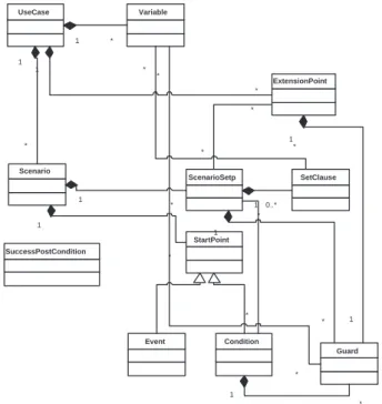
Fig. 1.An object oriented metamodel of the use case model
instruc-tions which assigning new values to these variables. The use case scenario can contain initiation triggers. They define situations when the use case must start, i.e. they iden-tify situations when external events cause an use case invocation. Sometimes, there are many ways to end use case and the termination and postcondition describe these situations. Termination is a list of success/failure and final options. Postcondition is a kind of formal commitment which is satisfied when use case ends. Figure 1 shows a sample object-oriented metamodel of the use case model.
3. Formal model
To perform formal validation of use cases we transform its specification to a transition system. Each step in the use case scenario is modeled as a transition between states. Transitions can be labeled by guards and assignments to variables, whereas states can be labeled with Boolean functions representing conditions: extension points, pre- and postconditions.
To avoid defining syntax of expressions appearing in a use case specification, we convert them to a set of Boolean variables and assignments of values to variables. Each Boolean variable corresponds to a test expression appearing in guards or extension point conditions of use case specification, e.g.:
v1 ≡ payment=cash v2 ≡ payment=creditcard
v3 ≡ ¬queue.empty()
v4 ≡ sessionexpired v5 ≡ debit>0
LetV ={v1, v2, . . . , vn}, wheren >0, be an enumerable set of Boolean variables.
FunctionVal:V → {true,false}is a valuation function. We will denote byVal(i) (or
simplyvi where this does not imply ambiguities) a value ofi-th variable.Pred(V) is
a set of predicates defined over a set of variablesV.
LetC be a set of logical constraints describing dependencies between variables.
Any valid valuation function must satisfy constraints Val |=C. Constraints should
allow undefined values.
Let us consider the following example. For variables v1 andv2 coresponding to
test expressions payment = cash and payment = creditcard constraints should be
defined as:
C= (¬v1∧ ¬v2)∨(v1∧ ¬v2)∨(¬v1∧v2)
The above formula specifies thatpayment should be undefined (neither by cash, nor
by card) or cash only or card only.
A modification (assignment) function f: Val → Val changes the valuation of
logical variables. It is assumed, that for anyVal2=f(Val1) ifVal1|=C thenVal2|=
Definition 1. Use case model UCM is a tuple UCM =hS, T, V,Assign, G, s0,Cond,
Val0i, where
S – is a set of states,
T – whereT ⊆S×S is a transition function,
V – is a set of Boolean and atomic variables, Assign – is a partial function:T →2F
, i.e. any transition can be linked with a set of assignments,
G– is a partial functionT →Pred(V),
s0 – is the initial state,
Cond – is a partial function S → Pred(V), i.e. this function represents post- and preconditions that can be assigned to states,
Val0 – is the initial valuation of variables, satisfying card Pred(V) = Cond(s0) and
Pred(Val0) =true.
1
2
5 4 3
6
[condition1]
[condition2]
Nondeterministic choice and loop
7 x:=a | x:=b
6
7' 7'’ x:=a x:=b not [condition 1]
not [condition2]
Choice between assignments equivalent to nondeterminism
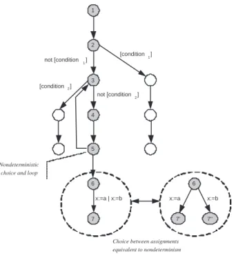
Fig. 2.Use case model
Figure 2 shows typical patterns that can appear in UCM:
•deterministic choice guarded by expressions at states 2 and 3,
•loops (states 3-4-5) with accompanying nondeterministic choice – an actor
•nondeterministic assignment – transition 6-7 is labeled with two assignments
x:=a andx:=b what corresponds to two transitions 6-7’ labeled with x:=a
and 6-7” labeled withx:=b.
4. Modeling relations in use case specifications
Use case specification usually takes the form of a scenario expressed in natural lan-guage. In the presence of includes, extends or inheritance relations the scenario should be consistent with constraints imposed by those relations. The include relation im-plies calling the included use case in a step of the basic use case. The extends relation corresponds to linking scenarios of extending use case at a certain extension point. We treat the inheritance as an obligation that a specialized version of the some general use case preserves its set of pre- and postconditions.
4.1. Include
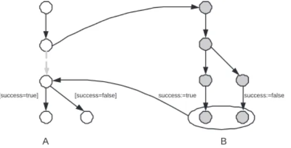
If use case A includes use case B it implies an obligation. In a step of main or al-ternative scenario of A the use case B should called. This corresponds to replacing transition in a model of A by the model of B (Figure 3) and linking initial and final states. If the included use case defines variables, they are inserted to the set of vari-ables of the model of main use case. This allows checking failures in included use case after calling it by appropriate guards in the scenarios of main use case.
A B
success:=true success:=false [success=true] [success=false]
Fig. 3.Modeling include relation
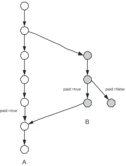
4.2. Extends
A
B paid:=true
paid:=true
paid:=false
Fig. 4.Modeling extends relation
4.3. Inheritance
The inheritance relation between two use cases: the base and the derived implies that the derived use case delivers the same results as the base use case while manifesting different behavior. The typical example is shown in Figure 5. An abstract use case
Identify User has two specializations: Identify User By Retina Scan and Identify User By Fingerprint. Those methods of identifications base on different principles and have different steps, however both result the same result: the status of user identification.
Identify User
Identify User By Retina Scan Identify User By Fingerprint
Fig. 5.Inheritance between use cases
Figure 6 shows a model of the use case Identify User. For a given precondition
(true) it leads to two states annotated with different postconditionsidentified =true
Figure 3). Calling use case may then test postconditions referring to variables defined
in scope of Identify User.
Identify User Pre [true]
Post [identified=true] Post [identified=false]
Fig. 6.Model of generalized use case
It is assumed that specialized use cases can be used in any context, where the base use case can be called (included). In Figure 7 a model of specialized use case
Identify User by Retina Scan is presented. Although more expanded, it preserves the pre and postconditions. In fact, we may expect that the derived use case has identical preconditions and its postconditions form a subset of postconditions in base use case (derived use case may narrow but not widen the set of postconditions). Moreover, for any trace in the model UCM of derived use case transforming a precondition into a postcondition, analogous trace should exist in the model of base use case.
Pre [true]
Post [identified=true] Post [identified=false]
Identify User By Retina Scan
Fig. 7.Model of specialized use case
5. Verification of UCM
5.1. Correctness of use case model
Let us consider a finite trace representing behavior of UCM. The tracesi a sequence
of states and valuation of variables starting with the initial values s0 and Val0. σ=
(s0,Val0),(s1,Val1), . . . ,(sn,Valn).
For each subsequent pairs (si
−1,Vali−1) and (si,Vali) the following conditions
holds: 1.ti= (si
2.G(ti)(Vali−1) =true
3. ifVali−16=Vali thenf ∈Assign(t) :f(Vali−1) =Vali
4.∀s∈S\ {sn}: (sn, s)∈/ T or ∃s∈S\ {sn}: (sn, s)∈T∧G(sn, s)(Valn) =false
Definition 2. We define a set of final states of UCM as F S = {s ∈ S :
¬∃snext.(s, snext)∈T}. The trace σis correct iff:
1.sn ∈F S
2. Cond(Valn) =true
Definition 3. Let L(UCM) be a set of all traces of UCM satisfying conditions (1-4). The UCM model is correctiff:
1.∀σ∈L(UCM)σis correct 2.∀t= (s1, s2)∈T ∃σ∈L(UCM),
σ= (s0,Val0), . . . ,(si−1,Vali−1),(si,Vali), . . . ,(sn,Valn) :s1=si−1, s2=si
5.2. Model verification
Verification of UCM model consists in systematic exploration of its state space and
constructing an execution graph Γ = (V, E) modeling its behavior. Each vertexvi∈V
is labeled with the pair (si,Vali). An edgee∈Ein the graph is labeled by a transition
t∈T in UCM and an assignment functionf ∈Assign(t).
Two vertices v1 = (s1,Val1) and v2 = (s2,Val2) are linked by an edge e12 =
(t12, f12) if the following conditions are satisfied:
1.t12= (s1, s2)∈T
2.G(t12)(Val1) =true
3.f12∈Assign(t12)
4.Val2=f12(Val1)
As it can be observed, the graphGrepresents in fact a Kripke structure [6] or it can
be easily transformed to it by removing labeling of edges and adding extra self-loops
at vertices having no successors. The process of building graphGfollows the method
of building occurrence graph for Petri nets described in [17]. It starts with an initial
graph Γ0 = (V0, E0), where V0 = (s0,Val0), E0 = ∅. At each step a new graph Γi
is constructed from a graph Γi−1 by adding an edgeei and a vertex vi to the graph
Γi
−1. This is done by selecting a starting vertexvs= (ss,Vals), a candidate transition
ti∈ {(s1, s2)∈T :s1=ss}, checking its guard and selecting an assignment function
fi∈Assign(ti). If the edgeei= (ti, fi) is not present inEi−1, graph Γiis constructed
by calculating Ei = Ei−1∪ {ei} and Vi = Vi−1∪ {(si,Vali)}, where ti = (ss, si)
andVali=f(Vals). The process terminates if all edges labeled with pairs (ti, fi) are
present in the graph Γi−1.
It can be observed that the graph Γ has following properties:
•its finite, as setsS and the set valuations of Boolean variables are finite,
•any trace of UCM execution represents a path in the graph.
•for each vertex v= (s,Val) with no outgoing edgev should satisfy:s∈F S and Cond(Val) =true.
•for any transitiont∈T the set of edgesEshould contain an edge labeled witht.
5.3. Logic verification
Another way of system’s verification is an analysis of correctness using the methods of formal logic. Such analysis enables checking whether our inference procedures pre-serve truth, which is of fundamental importance in validation of modeled systems. It can be observed increasing of importance of non-classical logics as they are close to the natural inference mechanisms. Particularly noteworthy is temporal logic which originates from modal logic. It allows to reason about the system behavior taking into account its relations with time. However, temporal logic is not focused on time measurement and more important are temporal relationships among events such as precedence and sequence of events.
Definition 4. Formal logic is a structureL =hF,I,|=i, where F is a set of syntac-tically correct formulae, I is a set of legal interpretations, and |=⊆ I × F is a rela-tionship that combines syntax and semantics of a logic.
The formal definition of the syntax and semantics of temporal logic can be found in many works, e.g. [9]. Thus, treating these concepts as defined, let us define further ones.
Definition 5. Temporal logic formula P is satisfied, if there is any interpretation I
such that I|=P, i.e.Iis a model for formulaP. FormulaP is called valid, or simply
tautology, if for every interpretation I there isI|=P.
There are many ways of logical inference, but here attention will be paid in two key methods of temporal logic inference about modeled system. The first one is called the deductive method. It is based on a logical system which is build in such a way that there are some rules of inference which contain assumptions that lead to the conclusions. This makes possible to introduce a formal scheme which allows to obtain new sentences in a formal way. These new sentences are theorems in a logical sys-tem. Therefore, the construction of a system of logical inference requires to propose sentences recognized by the system as its assumptions, i.e. sentences which do not require proofs, and rules of inference. These sentences are schemes which allow trans-formation of some valid sentences in the other valid sentences. However, this is done within the formal language. On the other hand, the inference rules relate to some metalanguage and they are reliable inference patterns. Construction of a deductive system must take into account a number of its properties, including the structure of time domain, which in general is a fairly complex process. However, axiomatic and
deductive system for thesmallest temporal logicis defined ([5]) as an extension of the
classical propositional calculus about axiom(P ⇒Q)⇒(P ⇒Q) and inference
rule |−P
An alternative way of inference is themethod of semantic tableau(e.g. [8]). In this method, an attempt to prove a formula by examining the complementary formula, i.e. its negation, and then lead to a contradiction. The procedure starts by a placing the complementary formula in the root of a tree, and then other subtrees are generated. Building the tree is achieved through an application of some defined rules. Some of the generating rules come from classical logic, but others are specific to temporal logic. The purpose of a such procedure is to find contradictions in various branches of the tree. This, in turn, means that there is an absence of a contradiction for the initial
formula. Thus, the tree is called closed if in each branch was found a contradiction.
The method of semantic tableau can be automated. What’s more, the method has an advantage over the deductive method. It follows from the fact that it is easier to find the place of potential error which is simply the appropriate branch of the tree. In addition, the method is characterized by a lower complexity, which arises from the fact that the generated tree has less and less complex formulae at each stage. Proving the desired property of the modeled system consists in the logical
implicationsP ⇒Q, whereP is a conjunctionP =p1∧p2∧. . .∧pn of all formulas
which constitute the system specification, and Qis a formula expressing the desired
property. It is interpreted that the examined property is a logical consequence of the system specification. Of course, the key issue is the careful identification of formulas which make up the modeled system.
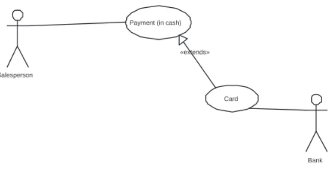
6. Example
Let us consider an example. It deals with the classical problem of the choice of payment method for goods. A common solution to this problem is presented in Figure 8. and the scenario for this problem is presented in Table 1.
Payment (in cash)
Card Salesperson
Bank «extends»
Fig. 8.Use case implementation using one extended use case
Table 1
Scenario for use casePayment (in cash)
Precondition
Debit undefined value
PaymentMethod undefined value
Postcondition for success
Debit Debit= 0
PaymentMethod PaymentMethod=cash∨
PaymentMethod=card
Postcondition for failure
Debit Debit>0
PaymentMethod PaymentMethod=cash∨
PaymentMethod=card
Main scenario
1. System displays the customer’s account
Debit:= anynonnegativevalue
2. System introduces a standard method of payment
PaymentMethod:= cash
3. Salesperson verifies the choice of method of payment
Guard: [PaymentMethod=cash]
4. Salesperson accepts payment and confirms it to the system
Debit:= 0
Alternative
2.a. Guard: [Debit= 0]
2.a.1. System displays information that no payment is needed and use case terminates
4.a. Payment cannot be realized 4.a.1. Use case terminates
Extensions
3.a. Payment in card PaymentMethod:= card
Model verification
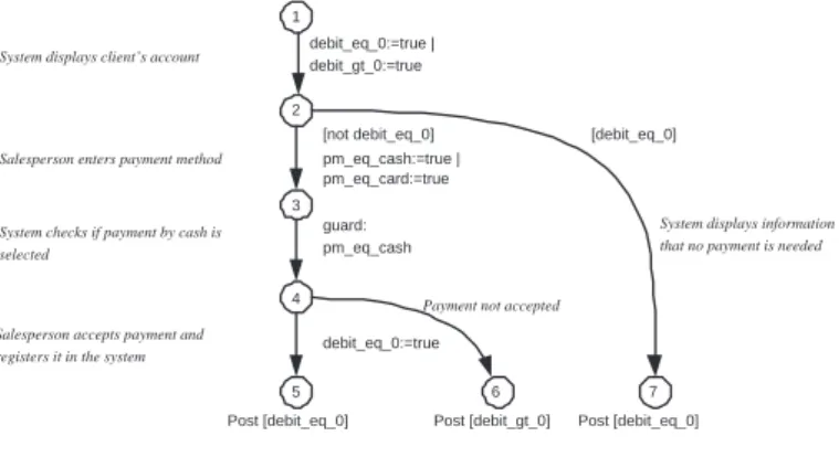
Let us consider the formal analysis of the last solution. Figure 9 shows an example
of UCM for the use casePayment (in cash). The conditions in use case specifications:
debit = 0, debit >0,PaymentMethod =cash andPaymentMethod =card are
rep-resented by Boolean variables: debit eq0, debit gt0, pm eq cash, pm eqcard. The
constraints Cfor the variables are:
(¬debit eq 0∧debit gt0)) ∧ ((¬pm eq cash∧ ¬pm eq card)∨ (¬pm eq cash∧pm eq card)∨(pm eq cash∧ ¬pm eq card))
Valuations of Boolean variables (debit eq0,debit gt 0,pm eqcash, pm eqcard) we
will represent by strings containingT andF letters. The initial valuation assigns false
to all variables, thus corresponding string isFFFF.
1
2
3
4 System displays client’s account
Salesperson enters payment method
System checks if payment by cash is selected
5 Salesperson accepts payment and registers it in the system
pm_eq_cash:=true | pm_eq_card:=true
guard: pm_eq_cash
debit_eq_0:=true
Post [debit_eq_0]
6 Payment not accepted
7 [debit_eq_0]
System displays information that no payment is needed [not debit_eq_0]
Post [debit_gt_0] Post [debit_eq_0] debit_eq_0:=true |
debit_gt_0:=true
Fig. 9.Use case model example
In the Figure 10 Γ graph for the UCM from Figure 9 is presented. Each vertex is annotated with the state number and the string representing valuation of Boolean variables. Edges of the graph are annotated with assignments to the variables.
1,FFFF
2,FTFF 2,TFFF
3,FTTF 3,FTFT
4,FTTF
5,TFTF 6,FTTF 7,TFFF
debit_eq_0:=true debit_gt_0:=true
pm_eq_cash:=true pm_eq_card:=true
debit_eq_0:=true debit_gt_0:=false
Fig. 10.Γ graph
It can be observed that for the leaf vertices [5,TFTF], [6,FTTF] and [7,TFFF]
postconditions assigned to states evaluate to true, thus the traces leading to them are
has no successor and does not belong to the set of final statesF S. The trace [1,FFFF]
[2,FTFF] [3,FTFT] can be classified as incorrect, what reveals incorrectness of the
isolated use case Payment (in cash). This however can be fixed if the extending use
case Card is defined and its UCM model is merged with the model in Figure 9 as
described in section 4.2.
Logic verification
The use case specification should be carefully constructed and divided to the follow-ing items: main scenario, alternative (scenario), extensions, etc. However, the model presented here is relatively small and therefore the specification (Table 1) of the (use case) model will be considered a whole. First, let us consider the possibility of setting a standard form of payment:
♦pm eqcash (1a)
On the other hand, the customer is left to the choice of the other form of payment:
♦(pm eqcash ⇒♦(pm eq cash∨pm eqcard)) (1b)
If the debit is not positive then payment (in card) will not be made:
(debit eq 0⇒ ¬♦pm eqcard) (1c)
It is not possible to change the form of payment in card:
(pm eqcard ⇒ ¬♦pm eq cash) (1d)
Now, let us consider some expected liveness and safety properties. The basic safety property says that it is not possible to request two forms of payment:
¬(pm eq cash∧pm eq card) (2a)
The basic liveness property express the transition from precondition to postconditions both for success and failures:
¬(debit eq0∨debit gt 0)∧ ¬(pm eq cash∨pm eq card)⇒
♦((debit eq 0∨debit gt0)∧(pm eqcash∨pm eqcard)) (2b)
7. Conclusion
In this paper a formal model of use cases, enabling application of formal methods for a system verification is proposed. There are two ways of formal reasoning about the modeled system. The first method refers to states’ exploration while the other one refers to the symbolic inference using temporal logic. An example of uses case is analyzed taking into account two complementary ways of verification. Careful and precise modeling of the use case diagrams is very important not only for understanding the system itself, but there is also the ability to automatically, or semi-automatically, generate a number of UML diagrams based on the use cases documentation, c.f. [15]. Future work will include defining a formal language of the use case specification that would allow to define both narrative part in natural language and operations on formally defined sets of variables. Presented in section 2 metamodel indirectly defines the scope of such language. It is planned to develop a tool enabling automatic translation of use case specification to the UCM model. It is planed also to investigate the possibility of automatic, or semi-automatic, generation of temporal logic formulas for the modeled system. Alternative to the model checking presented here is the model checking with temporal logic, i.e. when a model is specified as a transition system but properties are expressed as temporal logic formulas.
References
[1] Back R.-J., Petre L., Porres Paltor I.: Analyzing UML Use Case as Contracts.
Proceedings of UML’99, Second International Conference on the Unified Modeling Language. (Lecture Notes in Computer Science, 1723), Springer Verlag 1999, pp. 518–533.
[2] Barnett M., Grieskamp W., Schulte W., Tillmann N., Veanes M.: Validating
Use-Cases with the AsmL Test Tool. Proc. of the 3rd International Conference on Quality Software (QSIC’03). IEEE Computer Society 2003.
[3] Barrett S., Sinnig D., Chalin P., Butler G.:Merging of Use Case Models: Semantic
Foundations. 3rd International Symposium on Theoretical Aspects of Software Engineering, IEEE Computer Society 2009, pp. 182–189.
[4] Bartsch K., Robey M., Ivins J., Lam C.P.: Consistency Checking between Use
Case Scenarios and UML Sequence Diagrams. International Conference on Soft-ware Engineering, Innsbruck, 2004. IASTED/ACTA Press 2004.
[5] van Benthem J.:Temporal Logic. [in:]Handbook of Logic in Artificial Intelligence
and Logic Programming. vol. 4, Clarendon Press 1993–95, pp. 241–350.
[6] Clarke E. M. Jr., Grumberg O., Peled D. A.:Model Checking. MIT Press 1999.
[7] Cockburn A.:Writing Effective Use Cases. Addison-Wesley 2001.
[8] D’Agostino M., Gabbay D.M., H¨ahnle R., Posegga J. (eds):Handbook of Tableau
[9] Emerson E. A.: Temporal and Modal Logic.Handbook of Theoretical Computer Science, vol. B: Formal Models and Semantics, Elsevier, MIT Press 1990, pp. 995– 1072.
[10] Fowler M.:UML Distilled. 3rd Edition. Addison-Wesley 2004.
[11] Hurlbut R.: A survey of approaches for describing and formalizing use-cases.
Technical Report 9703, Department of Computer Science, Illinois Institute of Technology 1997.
[12] Jacobson I.:Object-Oriented Development in an Industrial Environment. Proc. of
OOPSLA’87, special issue of SIGPLAN Notices. vol. 22, 12, 1987, pp. 183–191.
[13] Klimek R., Skrzyński P., Turek M.: Automatic verification of the model at the
requirements analysis phase [in Polish]. 12th National Conference of Software Engineering, Poland, Gdańsk, September 27-29, PWNT 2010, pp. 209–216.
[14] K¨osters G., Six H.-W., Winter M.: Validation and Verification of Use Cases
and Class Models. 7th International Workshop on Requirements Engineering: Foundations for Software Quality (REFSQ’2001, Proc.), 2001.
[15] Król T.: The simulation of use cases [in Polish]. Master thesis (superviser:
R. Klimek). AGH University of Science and Technology 2007.
[16] Pohl K., Haumer P.:Modelling Contextual Information about Scenarios. Proc. of
the Third International Workshop on Requirements Engineering: Foundations of Software Quality REFSQ’97, Barcelona, 1997, pp. 187–204.
[17] Reisig W.: Petri Nets – An Introduction. (EATCS Monographs on Theoretical
Computer Science, Volume 4). Springer Verlag 1985.
[18] Saeki M., Kaiya H., Hattori S.:Applying a Model Checker to Check Regulatory
Compliance of Use Case Models. Proc. of CAiSE Forum 2009.
[19] Shen W., Liu S.:Formalization, Testing and Execution of a Use Case Diagram.
ICFEM 2003 International Conference on Formal Engineering Methods, Singa-pore, 2003. (Lecture Notes in Computer Science, 2885), Springer Verlag 2003, pp. 68–85.
[20] Zhao J., Duan Z.:Verification of Use Case with Petri Nets in Requirement
Anal-ysis. Proc. of the International Conference on Computational Science and Its