UML @ Classroom
Martina Seidl · Marion Scholz
Christian Huemer · Gerti Kappel
An Introduction to
More information about this series at http://www.springer.com/series/7592
undergraduates studying in all areas of computing and information science. From core foundational theoretical material to final-year topics and applications, UTiCS books take a fresh , concise , and modern approach and are ideal for self-study or for a one- or two-semester course. The texts are all authored by established experts in their fields, reviewed by an international advisory board, and and
Christian Huemer • Gerti Kappel
UML @ Classroom
Johannes Kepler University Linz Vienna University of Technology
Linz,Austria Vienna, Austria
Christian Huemer Gerti Kappel
Vienna University of Technology Vienna University of Technology
Vienna, Austria Vienna, Austria
Tanslator Tracey Duffy TSD Translations
Copyright © 2012 by dpunkt.verlag GmbH, Heidelberg, Germany. Title of the German original: UML @ Classroom
ISBN 978-3-89864-776-2
Translation Copyright © 2014 by Springer International Publishing AG. All rights reserved.
ISSN1863-7310 ISSN2197-1781 (electronic) ISBN 978-3-319-12741-5 ISBN 978-3-319-12742-2 (eBook) DOI 10.1007/978-3-319-12742-2
Springer Cham Heidelberg New York Dordrecht London Library of Congress Control Number: 2015930192
© Springer International Publishing Switzerland 2015
Printed on acid-free paper
Springer International Publishing AG Switzerland is part of Springer Science+Business Media (www.springer.com)
Undergraduate Topics in Computer Science Series Editor
Ian Mackie
Advisory Board
Samson Abramsky, University of Oxford, Oxford, UK
Karin Breitman, Pontifical Catholic University of Rio de Janeiro, Rio de Janeiro, Brazil Chris Hankin, Imperial College London, London, UK
Dexter Kozen, Cornell University, Ithaca, USA
Andrew Pitts, University of Cambridge, Cambridge, UK
Hanne Riis Nielson, Technical University of Denmark, Kongens Lyngby, Denmark Steven Skiena, Stony Brook University, Stony Brook, USA
Iain Stewart, University of Durham, Durham, UK
This work is subject to copyright. All rights are reserved by the Publisher, whether the whole or part of the material is concerned, specifically the rights of translation, reprinting, reuse of illustrations, recitation, broadcasting, reproduction on microfilms or in any other physical way, and transmission or information storage and retrieval, electronic adaptation, computer software, or by similar or dissimilar methodology now known or hereafter developed.
The use of general descriptive names, registered names, trademarks, service marks, etc. in this publication does not imply, even in the absence of a specific statement, that such names are exempt from the relevant protective laws and regulations and therefore free for general use.
The challenges in today’s software development are diverse and go far beyond implementation tasks. They range from requirement spec-ification over system design and implementation to maintenance and further adaptation of the software—to name just a few phases in the software life cycle. In all of these phases of the software develop-ment process, many people with different backgrounds and experiences are usually involved. These people need a common language for ef-ficient communication. Obviously, such a language should be as pre-cise as possible without the ambiguities of a natural language. For this purpose, modeling languages have emerged. They are used to create sketches and blueprints for software systems, which in turn serve as a basis for the implementation or even automatic generation of exe-cutable code. In the area of object-oriented software development, the Unified Modeling Language (UML) was able to prevail. Of course, to use the language correctly and efficiently, it is necessary to understand the concepts offered by UML. Since 2006, we have offered the course “Object-Oriented Modeling” at the Vienna University of Technology. This course is mandatory for computer science and business informat-ics students in their first year. Overall, we have up to 1,000 students per year who attend our course. To deal with such a huge number of stu-dents while keeping high quality standards, much effort has been spent on the preparation of such a course. This includes the overall organi-zation, course material, and e-learning support. Parts of the course de-sign have been presented at the Educators’ Symposium of the MODELS conference [8, 9, 10, 11, 7, 46]. We teach the basics of object-oriented modeling by means of UML.
In particular, we teach
• class and object diagrams, • sequence diagrams, • state machine diagrams, • activity diagrams, and • use case diagrams
as well as their interrelations. For this purpose, we introduce the syntax (the notation of the language elements), the semantics (the meaning of the language elements), and the pragmatics (how to use the language elements) of these UML diagrams. They cover the most essential con-cepts of object-oriented modeling and are used in many different stages of the software development process. The course is designed for stu-dents who already know the basic concepts of object-oriented program-ming languages such as Java or C#, but still have no practical experi-ence in software engineering. Based on our comprehensive experiexperi-ence in teaching UML, we wrote the book UML@Classroom. In this book, we address both readers who wish to learn UML in a compact but nev-ertheless precise manner and teachers whom we want to provide with inspiration for their own course exercises with our extensive example repertoire. We teach UML as close to the standard as possible and illus-trate all concepts using intuitive examples. The book is complemented by a website, which contains a complete set of slides to teach the con-tents of the book as well as teaching videos and e-learning material (http://www.uml.ac.at/).
Acknowledgments
We would like to thank the many people who supported us in the suc-cessful completion of this book. Very special thanks go to our families who showed great patience for this book project. We are deeply indebted to Katja Hildebrandt (Vienna University of Technology) for drawing all the figures of this book and for supporting us with a million of other things. We would like to thank Ralf Gerstner from Springer and Christa Preisendanz from dpunkt.verlag for making this English version possi-ble. Further, we would like to thank Tracey Duffy for the good collabo-ration on the translation of the German version of this book into English and Jeremy Gibbons (University of Oxford) for the careful proofreading and the very valuable feedback. Finally, we would like to acknowledge the input we got from our students over the years which was one of the main motivators for writing this book.
1 Introduction. . . 1
1.1 Motivation . . . 1
1.2 Models . . . 2
1.3 Object Orientation . . . 6
1.3.1 Classes . . . 6
1.3.2 Objects . . . 6
1.3.3 Encapsulation . . . 7
1.3.4 Messages . . . 7
1.3.5 Inheritance . . . 7
1.3.6 Polymorphism . . . 8
1.4 The Structure of the Book . . . 9
2 A Short Tour of UML . . . 11
2.1 The History of UML . . . 11
2.2 Usage . . . 14
2.3 Diagrams . . . 15
2.3.1 Structure Diagrams . . . 17
2.3.2 Behavior Diagrams . . . 19
2.4 Diagrams Presented in this Book . . . 21
3 The Use Case Diagram. . . 23
3.1 Use Cases . . . 24
3.2 Actors . . . 25
3.3 Associations . . . 27
3.4 Relationships between Actors . . . 28
3.5 Relationships between Use Cases . . . 30
3.6 Examples of Relationships . . . 33
3.7 Creating a Use Case Diagram . . . 34
3.7.1 Identifying Actors and Use Cases . . . 34
3.7.2 Describing Use Cases . . . 35
3.7.3 Pitfalls . . . 37
3.7.4 A Final Example . . . 42
3.8 Summary . . . 46
4 The Class Diagram. . . 49
4.1 Objects . . . 50
4.2 Classes . . . 52
4.2.1 Notation . . . 53
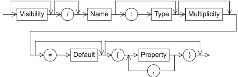
4.2.2 Attributes . . . 54
4.2.3 Multiplicities . . . 55
4.2.4 Operations . . . 56
4.2.5 Visibility Markers . . . 58
4.2.6 Class Variables and Class Operations . . . 59
4.3 Associations . . . 60
4.3.1 Binary Associations . . . 60
4.3.2 N-Ary Associations . . . 64
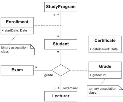
4.4 Association Classes . . . 65
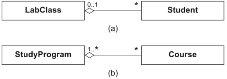
4.5 Aggregations . . . 67
4.5.1 Shared Aggregations . . . 68
4.5.2 Compositions . . . 68
4.6 Generalizations . . . 69
4.6.1 Inheritance . . . 70
4.6.2 Classification . . . 72
4.7 Abstract Classes vs. Interfaces . . . 72
4.8 Data Types . . . 75
4.9 Creating a Class Diagram . . . 76
4.9.1 Generalizations . . . 78
4.9.2 Associations and Aggregations . . . 78
4.10 Code Generation . . . 80
5 The State Machine Diagram. . . 85
5.1 States and State Transitions . . . 86
5.2 Types of States . . . 89
5.3 Types of State Transitions . . . 92
5.4 Types of Events . . . 94
5.5 Composite States . . . 96
5.5.1 The Orthogonal State . . . 97
5.5.2 Submachines . . . 98
5.5.3 Entry and Exit Points . . . 99
5.5.4 The History State . . . 101
5.6 Sequence of Events . . . 102
6 The Sequence Diagram . . . 107
6.1 Interaction Partners . . . 108
6.2 Exchanging Messages . . . 110
6.3 Messages . . . 112
6.4 Combined Fragments . . . 115
6.4.1 Branches and Loops . . . 116
6.4.2 Concurrency and Order . . . 119
6.4.3 Filters and Assertions . . . 125
6.5 Further Language Elements . . . 126
6.5.1 Interaction References . . . 127
6.5.2 Gates . . . 128
6.5.3 Continuation Markers . . . 129
6.5.4 Parameters and Local Attributes . . . 129
6.5.5 Time Constraints . . . 130
6.5.6 State Invariants . . . 132
6.6 Creating a Sequence Diagram . . . 133
6.6.1 The Connection between a Class Diagram and a Sequence Diagram . . . 133
6.6.2 Describing Design Patterns . . . 135
6.7 The Communication, Timing, and Interaction Overview Diagrams . . . 136
6.8 Summary . . . 139
7 The Activity Diagram. . . 141
7.1 Activities . . . 142
7.2 Actions . . . 143
7.2.1 Event-Based Actions . . . 144
7.2.2 Call Behavior Actions . . . 145
7.3 Control Flows . . . 146
7.4 Object Flows . . . 154
7.5 Partitions . . . 156
7.6 Exception Handling . . . 159
7.7 Concluding Example . . . 161
8 All Together Now . . . 167
8.1 Example 1: Coffee Machine . . . 167
8.2 Example 2: Submission System . . . 171
8.3 Example 3: Data Type Stack . . . 180
8.4 Summary . . . 182
9 Further Topics. . . 183
9.1 Structuring Models . . . 183
9.1.1 Packages . . . 184
9.2 The UML Metamodel . . . 186
9.3 UML Extension Mechanisms . . . 187
9.3.1 Stereotypes and Profiles . . . 189
9.3.2 Applying Stereotypes of a Profile . . . 191
9.4 Model-Based Software Development . . . 192
References. . . 195
Introduction
TheUnified Modeling Language(UML) is a consolidation of the best Unified Modeling Language (UML) practices that have been established over the years in the use of
model-ing languages. UML enables us to present the widely varymodel-ing aspects of a software system (e.g., requirements, data structures, data flows, and information flows) within a single framework using object-oriented concepts. Before we venture too deeply into UML, however, in this chapter we first explain why modeling is an indispensable part of soft-ware development. To do this, we look at what models are and what we need them for. We briefly recapitulate the basic concepts of object orientation before continuing with an overview of the structure of the book.
1.1 Motivation
Imagine that you want to develop a software system that a customer has ordered from you. One of the first challenges you are confronted with is clarifying what the customer actually wants and whether you have understood the customer’s exact requirements for the prospective system. This first step is already critical for the success or failure of your project. The question is, how do you communicate with your customer? Natural language is not necessarily a good choice as it is imprecise and ambiguous. Misunderstandings can easily arise and there is a very great risk that people with different backgrounds (e.g., a computer scientist and a business manager) will talk at cross-purposes, which can have serious consequences.
What you need is to be able to create a model for your software. This model highlights the important aspects of the software in a clear form
1
of notation that is as simple as possible but abstracts from irrelevant details, just like models in architecture, e.g., construction plans. A con-struction plan for a building contains information such as the floor plan. Construction materials to be used are not specified at this point in time; they are irrelevant and would make the plan more complicated than nec-essary. The plan also does not contain any information about how the electrical cables are to be laid. A separate plan is created for this aspect to avoid presenting too much information at once. Just like in architec-ture, it is important in information technology that people with different backgrounds (e.g., architect and builder) can read, interpret, and imple-ment the model.
Modeling languageswere developed precisely for such scenarios and Modeling language
demonstrate clearly defined rules for a structured description of a sys-tem. These languages can betextual(e.g., a programming language such
as Java) or visual(e.g., a language that provides symbols for
transis-tors, diodes, etc. that can be combined with one another). Modeling languages can be designed for a specific domain, for example, for de-scribing web applications. On the one hand, thesedomain-specific mod-eling languagesprovide tools and guidelines for solving problems in a specific field efficiently; on the other hand, they can also be restrictive. Alternatively, modeling languages can be designed for general purpose use. The language UML, which is the subject of this book, is a general purpose modeling language. We will use UML to get to know the most important concepts of object-oriented modeling.
Object-oriented modeling is a form of modeling that obeys the Object-oriented
modeling object-oriented paradigm. In the following two subsections, we will look briefly at the notion of a model and the main concepts of object orientation. This will provide us with a good basis for our subsequent examination of object-oriented modeling with UML.
1.2 Models
Models allow us to describe systems efficiently and elegantly. Asystem System
is an integrated whole made up of components that are related to one another and influence each other in such a way that they can be per-ceived as a single, task-based or purpose-based unit. In this regard, they separate themselves from the surrounding environment [52]. Examples of systems are material things, such as cars or airplanes, ecological en-vironments, such as lakes and forests, but also organizational units such as a university or a company. In information technology, we are inter-ested in particular in software systems and thus in models that describe Software system
Software systems themselves are based onabstractionsthat repre- Abstraction sent machine-processible facts of reality. In this context, abstraction
means generalization—setting aside specific and individual features. Abstract is the opposite of concrete. Abstracting therefore means mov-ing away from specifics, distmov-inguishmov-ing the substance from the inciden-tal, recognizing common characteristics [29].
When creating software systems, it is extremely important to select Selecting means of abstraction suitable means of abstraction: on the one hand for the implementation,
but on the other hand also for the subsequent use of the software sys-tems. Choosing the correct means of abstraction makes programming easier. The individual parts then have simple and small interfaces. New functionality can be introduced without the need for extensive reorga-nization. Choosing the wrong means of abstraction might result in a number of nasty surprises during implementation: the interfaces will be complicated and it will be difficult to implement changes. You can only manage the ever-increasing complexity of modern software sys-tems with suitable means of abstraction [26]. This is where modeling can provide valuable services.
To develop a better understanding of modeling concepts, below we present widespread and generally recognized definitions of the notion of a model as well as the properties that a good model should possess.
The notion of a modelis important not only in information tech- Model nology but also in many other scientific disciplines (mathematics,
phi-losophy, psychology, economics, etc.). Derived from the Latin “modu-lus”, which designates a scale in architecture, during the Renaissance the word “modello” was used in Italy for an illustrative object intended to present the form and design of a planned building to a client and to clarify design and architectural questions. Over the subsequent cen-turies, the notion of a “model” has been used in various branches of science for a simplified description of complex facts from reality.
In 1973, Herbert Stachowiak proposed a model theory that is distin- Definition by Herbert Stachowiak
guished by three characteristics [48]:
1. Mapping:a model is always an image (mapping) of something, a representation of natural or artificial originals that can be models themselves.
2. Reduction:a model does not capture all attributes of the original, rather only those that seem relevant to the modeler or user of the model.
3. Pragmatism: pragmatism means orientation toward usefulness. A model is assigned to an original based on the following questions:
Models support a representation of a system that is reduced to the essentials in order to minimize the complexity of the system to man-ageable aspects. A system is usually described not by one single view but by a number of views that together produce a unified overall picture. Thus, one view might describe the objects involved and their relation-ship to one another; another view might describe the behavior of a group of objects or present the interactions between different objects.
Models must be created with great care and due consideration. Ac-Properties of models
cording to Bran Selic [47], five characteristics determine the quality of a model:
• Abstraction:a model is always a reduced representation of the sys-tem that it represents. Because the details that are irrelevant in a specific context are hidden or removed, it is easier for the user to understand the essence of the whole.
• Understandability:simply omitting irrelevant details is not enough
to make a model understandable. It is important to present the re-maining elements as intuitively as possible—for example, in a graph-ical notation. The understandability results directly from the expres-siveness of the modeling language. Expresexpres-siveness can be defined as the ability to present complex content with as few concepts as possi-ble. In this way, a good model reduces the intellectual effort required to understand the content depicted. For example, typical program-ming languages are not particularly expressive for a human reader as a lot of effort is required to understand the content of the program. • Accuracy:a model must highlight the relevant properties of the real
system, reflecting reality as closely as possible.
• Predictiveness:a model must enable prediction of interesting but not obvious properties of the system being modeled. This can be done via simulation or analysis of formal properties.
• Cost-effectiveness:in the long-run, it must be cheaper to create the
model than to create the system being modeled.
Models can be used for various purposes. Thus we distinguish be-tween descriptive and prescriptive models [17]. Descriptive models Descriptive model
show a part of the reality to make a specific aspect easier to under-stand. For example, a city map describes a city in such a way as to help a non-local person to find routes within the city. In contrast, prescrip-Prescriptive model
tive modelsare used to offer a construction manual for the system to be developed.
In this book, we look at how the different aspects of a software sys-tem can be modeled using a modeling language—the Unified Modeling Language—such that executable code can be derived either manually Executable code as
created. Incidentally, the executable code, developed in any program-ming language, such as Java, is also a model. This model represents the problem to be solved and is optimized for execution on computers.
To summarize, there are three applications for models [19]:
• Models as a sketch • Models as a blueprint
• Models as executable programs
Models are used as a sketch to communicate certain aspects of a Models as a sketch system in a simple way. Here, the model is not a complete mapping of
the system. Sketches are actually distinguished by their selectivity, as they are reduced to the essential aspects for solving a problem. Sketches often make alternative solutions visible. These are then discussed in the development team. Thus, models are also used as a basis for discussion. In contrast to the use of models as sketches, completeness is very
im-portant when models are used as ablueprint. These models must con- Models as a blueprint tain sufficient detail to enable developers to create ready-to-run systems
without having to make design decisions. Models used as blueprints of-ten do not specify the whole system, only certain parts. For example, the interface definitions between subsystems are defined in the model, whereby the developers are free to decide on the internal implementa-tion details. If the models are behavioral descripimplementa-tions, the behavior can also be simulated and tested to identify faults in advance.
Models as sketches and blueprints can be used for bothforward
engi-neeringandbackward engineering. In forward engineering, the model Forward and backward engineering
is the basis for creating code, while in backward engineering, the model is generated from the code to document the code in a clear and easily understandable way.
Finally, models can be used asexecutable programs. This means that Models as executable programs
1.3 Object Orientation
If we want to model in an object-oriented style, we must first clarify whatobject orientationmeans. The introduction of object orientation Object orientation
dates back to the 1960s when the simulation language SIMULA [24] was presented, building on a paradigm that was as natural to humans as possible to describe the world. The object-oriented approach corre-sponds to the way we look at the real world; we see it as a society of autonomous individuals, referred to as objects, which take a fixed place in this society and must thereby fulfill predefined obligations.
There is not only one single definition for object orientation. How-ever, there is a general consensus about the properties that character-ize object orientation. Naturally, objects play a central role in object-oriented approaches. Viewed simply, objects are elements in a system whose data and operations are described. Objects interact and commu-nicate with one another. In general, we expect the concepts described below from an object-oriented approach.
1.3.1 Classes
In many object-oriented approaches, it is possible to defineclassesthat Class
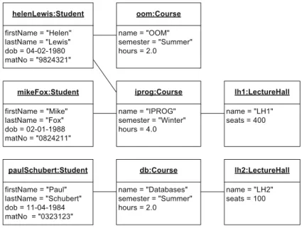
describe the attributes and the behavior of a set of objects (the instances of a class) abstractly and thus group common features of objects. For example, people have a name, an address, and a social security number. Courses have a unique identifier, a title, and a description. Lecture halls have a name as well as a location, etc. A class also defines a set of permitted operations that can be applied to the instances of the class. For example, you can reserve a lecture hall for a certain date, a student can register for an exam, etc. In this way, classes describe the behavior of objects.
1.3.2 Objects
The instances of a class are referred to as itsobjects. For example,lh1, Object
if the devices are of the same type. Here we refer toidenticaldevices
but not thesamedevice. The situation for concrete values of data types
is different: the number1, which is a concrete value of the data type Integer, does not have a distinguishable identity.
An object always has a certain state. A state is expressed by the values of its attributes. For example, a lecture hall can have the state
occupiedor free. An object also displays behavior. The behavior of an object is described by the set of its operations. Operations are triggered by sending a message.
1.3.3 Encapsulation
Encapsulationis the protection against unauthorized access to the inter- Encapsulation nal state of an object via a uniquely defined interface. Different levels
of visibility of the interfaces help to define different access authoriza-tions. Java, for example, has the explicit visibility markers public, private, andprotected, which respectively permit access for all,
only within the object, and only for members of the same class, its sub-classes, and of the same package.
1.3.4 Messages
Objects communicate with one another throughmessages. A message Message to an object represents a request to execute an operation. The object
it-self decides whether and how to execute this operation. The operation is only executed if the sender is authorized to call the operation—this can be regulated in the form of visibilities (see the previous paragraph)— and a suitable implementation is available. In many object-oriented
pro-gramming and modeling languages the concept ofoverloadingis sup- Overloading ported. This enables an operation to be defined differently for different
types of parameters. For example, the operator+realizes different
be-havior depending on whether it is used to add up integers (e.g.,1 + 1 = 2) or to concatenate character strings (e.g.,“a” + “b” = “ab”).
1.3.5 Inheritance
su-perclass) inherits all visible attributes and operations (specification and implementation) of the superclass. A subclass can:
• Define new attributes and/or operations
• Overwrite the implementation of inherited operations • Add its own code to inherited operations
Inheritance enables extensible classes and as a consequence, the cre-ation ofclass hierarchiesas the basis for object-oriented system devel-Class hierarchy
opment. A class hierarchy consists of classes with similar properties, for example,Person←Employee←Professor←...where
A←Bmeans thatBis a subclass ofA.
When used correctly, inheritance offers many advantages: reuse of program or model parts (thus avoiding redundancy and errors), consis-tent definition of interfaces, use as a modeling aid through a natural categorization of the occurring elements, and support for incremental development, i.e., a step-by-step refinement of general concepts to spe-cific concepts.
1.3.6 Polymorphism
In general terms,polymorphismis the ability to adopt different forms. Polymorphism
During the execution of a program, a polymorphic attribute can have references to objects from different classes. When this attribute is de-clared, a type (e.g., class Person) is assigned statically at compile time. At runtime, this attribute can also be bound dynamically to a sub-type (e.g., subclassEmployeeor subclassStudent).
A polymorphic operation can be executed on objects from different classes and have different semantics in each case. This scenario can be implemented in many ways: (i) via parametric polymorphism, better
1.4 The Structure of the Book
In Chapter 2 we give a short overview of UML by recapitulating the history of its creation and taking a brief look at its 14 different diagrams. Then, in Chapter 3, we introduce the concepts of the use case diagram. This diagram enables us to describe the requirements that a system to be developed should satisfy. In Chapter 4 we present the class diagram. This diagram allows us to describe the structure of a system. To enable us to model the behavior of a system, in Chapter 5 we introduce the state machine diagram, in Chapter 6 the sequence diagram, and in Chapter 7 the activity diagram. We explain the interaction of the different types of diagrams in Chapter 8 with three examples. In Chapter 9, we briefly examine advanced concepts that are of significant importance for the practical use of UML.
The concepts are all explained using examples, all of which are based on the typical Austrian university environment. In most cases they rep-resent heavily simplified scenarios. It is not our intention in this book to model one single, continuous system, as there is a high risk that in doing so we would become lost in a multitude of technical details. We have therefore selected examples according to their didactic benefit and their illustrative strength of expression. In many cases, we have there-fore made assumptions that, for didactic reasons, are based on simpli-fied presentations of reality.
A Short Tour of UML
Before introducing the most important concepts of UML in the follow-ing chapters, we first explain the background of this modelfollow-ing language. We look at how UML came into being and what the “U” for “Unified” actually means. We then answer the question of how UML itself is de-fined, that is, where do the rules come from that dictate what a valid model should look like in UML? Furthermore, we outline what UML is used for. Finally, we give a short overview of all 14 UML diagrams in the current version 2.4.1 of the UML standard specification. These diagrams can be used for modeling both structure and behavior.
2.1 The History of UML
The introduction of object-oriented concepts in information technology Origins of object orientation originates from the work of the early 1960s [12]. The first ideas were
implemented in systems such as Sketchpad, which offered a new, graph-ical communication approach between man and computer [28, 51].
Today, the programming language SIMULA [24] is regarded as the SIMULA first object-oriented programming language. SIMULA was primarily
used to develop simulation software and was not particularly widely used. It already included concepts such as classes, objects, inheritance, and dynamic binding [2].
The introduction of these concepts was the start of a revolution
in software development. In the subsequent decades, there followed Object-oriented programming languages a multitude of programming languages based on the object-oriented
paradigm [21]. These included languages such as C++ [50], Eiffel [31], and Smalltalk [28]. They already contained many of the important con-cepts of modern programming languages and are still used today.
11
The emergence and introduction of object orientation as a method in software engineering is closely connected to the appearance of object-oriented programming languages. Today, object orientation is a proven and well-established approach for dealing with the complexity of soft-ware systems. It is applied not only in programming languages but also in other areas, such as in databases or the description of user interfaces. As we have already discussed in Section 1.2, where we introduced the notion of a model, software systems are abstractions aimed at solv-ing problems of the real world with the support of machines. Procedural programming languages are not necessarily the most appropriate tools for describing the real world: the differences in concept between a nat-ural description of a problem and the practical implementation as a pro-gram are huge. Object-oriented propro-gramming was an attempt to develop better programs that, above all, are easier to maintain [12].
Over the years, object orientation has become the most important software development paradigm. This is reflected in object-oriented programming languages such as Java [4] or C# [32] and object-oriented modeling languages such as UML. However, the road to the current state-of-the-art of software development was long and winding.
In the 1980s, the programming language Ada, funded by the United Ada
States Department of Defense, was extremely popular due to its pow-erful concepts and efficient compilers [25]. Even back then, Ada sup-ported abstract data types in the form ofpackagesand concurrency in the form oftasks. Packages allowed the separation of specification and implementation and the usage of objects and classes of objects. Ada thus distinguished itself fundamentally from other popular languages of that time, such as Fortran and Cobol. As a consequence, there followed a great demand for object-oriented analysis and design methods to make the development of Ada programs easier. Due to the wide distribution of Ada and the pressure from the United States Department of Defense, these modeling methods were based specifically on the characteristics of Ada. Grady Booch was one of the first researchers to publish work Booch method
on the object-oriented design of Ada programs [5].
Over time, a number of further object-oriented modeling methods arose (see [12] for an overview). In general, the modeling methods had either a strong reference to programming languages, such as the Booch method, or a strong reference to data modeling, such as the Ob-OMT approach by
Rumbaugh et al. ject Modeling Technique(OMT) approach developed by James Rum-baugh et al. [42]. OMT supported the development of complex objects in the sense of an object-oriented extension of the entity-relationship model [14] which had been introduced for describing databases.
Independently of this, Ivar Jacobson et al. introduced the Object-OOSE approach by
In the 1980s and early 1990s, the modeling world was flooded with Method war a multitude of different modeling languages. Considerable effort was
required to deal with the resulting compatibility problems. The models of different project partners were often not compatible and it was not always possible to reuse models in different projects. The result was exhausting discussions about different notations, which detracted from the actual modeling problems. As new modeling languages were ap-pearing all the time, there was no clarity about which were worthy of investment and which were just a short-lived trend. If a language did not become accepted, all investments that had been made to establish it within a project or a company were generally lost. Looking back, this time of numerous approaches, often with the difference being only in the detail, is referred to as themethod war.
To put an end to this unsatisfactory situation, in 1996 the Object Object Management Group (OMG) Management Group(OMG) [33], the most important standardization
body for object-oriented software development, called for the specifica-tion of a uniform modeling standard.
In the previous year, 1995, Grady Booch, Ivar Jacobson, and James Rumbaugh had combined their ideas and approaches at the OOPSLA conference (OOPSLA stands for Object-Oriented Programming, Sys-tems, Languages, and Applications). Since then, Booch, Jacobson, and
Rumbaugh have often been called the “three amigos”. They set them- Three amigos selves the following objectives [1]:
• Use of object-oriented concepts to represent complete systems rather than just one part of the software
• Establishment of an explicit relationship between modeling concepts and executable program code
• Consideration of scaling factors that are inherent in complex and crit-ical systems
• Creation of a modeling language that can be processed by machines but can also be read by human beings
The result of their efforts was theUnified Modeling Language(UML) Unified Modeling Language (UML) which was submitted in version 1.0 in 1997 in response to the OMG
call. A number of former competitors were involved in the creation of version 1.1 that subsequently appeared in 1998. One of the main objec-tives was a consistent specification of the language core of UML which
is documented in themetamodel(see Chapter 9). The metamodel de- Metamodel fines which model elements the language UML provides and how to use
them correctly. For formulating constraints which the model elements
have to fullfill, theObject Constraint Language(OCL) [36], based on Object Constraint Language (OCL) predicate logic, was introduced. In subsequent versions, along with the
(XMI) [38] were added. In addition to these rather small changes, in XML Metadata
Interchange format (XMI)
2000 the OMG initiated a modernization process for UML. This finally led to the adoption of the language standard UML 2.0 in 2005. With the exception of small changes which, through interim versions, resulted in the current version 2.4.1, this is the language description of UML that we will get to know and use in this book.
Today, UML is one of the most widespread graphical object-oriented modeling languages. Despite the numerous revisions, its roots (Booch method, OMT, OOSE) are still clearly recognizable. UML is suitable for modeling both complex object relationships and processes with con-currency. UML is a general purpose modeling language, meaning that its use is not restricted to a specific application area. It provides lan-guage and modeling concepts and an intuitive graphical notation for modeling various application areas, enabling a software system to be specified, designed, visualized, and documented [43]. The result of modeling with UML is a graphical model that offers different views of a system in the form of various diagrams.
2.2 Usage
UML is not tied to a specific development tool, specific programming language, or specific target platform on which the system to be devel-oped must be used. Neither does UML offer a software development process. UML in fact separates the modeling language and modeling method. The latter can be defined on a project-specific or company-specific basis. However, the language concepts of UML do favor an iterative and incremental process [43].
UML can be used consistently across the entire software develop-Use in the software
development process ment process. At all stages of development, the same language concepts can be used in the same notation. Thus, a model can be refined in stages. There is no need for a model to be translated into another modeling lan-guage. This enables an iterative and incremental software development process. UML is well-suited for various application areas with different requirements regarding complexity, data volume, real time, etc.
The UML model elements and their correct use are specified in the UML metamodel [35]. The language concepts are defined so gener-Generic language
concepts ically that a wide and flexible applicability is achieved. To avoid re-stricting the use of UML, the standard is (intentionally) vague at vari-ous points, permitting different interpretations in the form of semantic Semantic variation point
2.3 Diagrams
In UML, a model is represented graphically in the form ofdiagrams. A Diagram diagram provides a view of that part of reality described by the model.
There are diagrams that express which users use which functionality and diagrams that show the structure of the system but without specify-ing a concrete implementation. There are also diagrams that represent supported and forbidden processes. In the current version 2.4.1, UML offers 14 diagrams that describe either the structure or the behavior of a system.
Diagram
Structure Diagram
Component Diagram
Deployment Diagram
Composition Structure Diagram Class
Diagram
Object Diagram Package
Diagram
Profile Diagram
Behavior Diagram
State Machine Diagram
Timing Diagram Sequence
Diagram Activity Diagram
Use Case Diagram
Interaction Diagram
Interaction Overview Diagram
Communication Diagram
Figure 2.1 UML diagrams
Figure 2.1shows a taxonomy of the 14 UML diagrams [35], giv-ing a very rough categorization. As the figure shows, we differentiate betweenstructure diagramsandbehavior diagrams. The behavior di-agrams include the interaction didi-agrams, which in turn consist of four diagrams (see Chapter 6).
A diagram is usually enclosed by a rectangle with a pentagon in the Notation for diagram frame
con-Figure 2.2
Examples of UML diagram frames
cd University
Building
*
teaches
attends
*
Professor Student
Course
*
*
Person
in
LectureHall
*
1*
sd Registration(course, date)
register(course, date)
register: ″ok″
:Student :Registration :Database
System
enter(course, date)
enter: ″ok″
tains two examples of diagram frames. In particular, it shows a class di-agram (cd) with the nameUniversityand a sequence diagram (sd) called Registrationwith the parameterscourseanddate.
A concept that may occur in all diagrams is thenote. A note can con-Note
Persons are not permitted to grade themselves
Person
grades
*
*
Figure 2.3 Example of a note
2.3.1 Structure Diagrams
UML offers seven types of diagrams for modeling the structure of a sys-tem from different perspectives. The dynamic behavior of the elements in question (i.e., their changes over time) is not considered in these dia-grams.
The Class Diagram
Just like the concepts of the object diagram (see next paragraph), the Class diagram (see Chapter 4)
Course
*
teaches
attends
* * *
Person
Prof. Student
concepts of theclass diagram originate from conceptual data model-ing and object-oriented software development. These concepts are used to specify the data structures and object structures of a system. The class diagram is based primarily on the concepts ofclass, generaliza-tion, andassociation. For example, in a class diagram, you can model that the classesCourse,Student, andProfessoroccur in a system. Profes-sors teach courses and students attend courses. Students and profesProfes-sors have common properties as they are both members of the classPerson. This is expressed by a generalization relationship.
The Object Diagram
Based on the definitions of the related class diagram, an object dia- Object diagram (see Chapter 4)
henryFoster :Professor
oom:Course
oop:Course
The Package Diagram
Thepackage diagramgroups diagrams or model elements according to Package diagram
Exam Administration
Student
common properties, such as functional cohesion. For example, in a uni-versity administration system, you could introduce packages that con-tain information about the teaching, the research, and the administrative aspects. Packages are often integrated in other diagrams rather than be-ing shown in separate diagrams.
The Component Diagram
UML pays homage to component-oriented software development by Component diagram
CentralData Administration
Library Administration
offering component diagrams. A component is an independent,
exe-cutable unit that provides other components with services or uses the services of other components. UML does not prescribe any strict separa-tion between object-oriented and component-oriented concepts. Indeed, these concepts may be combined in any way required. When specify-ing a component, you can model two views explicitly: the external view (black box view), which represents the specification of the component, and the internal view (white box view), which defines the implementa-tion of the component.
The Composition Structure Diagram
Thecomposition structure diagramallows a hierarchical decomposition Composition structure
diagram
Server Client Network
of the parts of the system. You can therefore use a composition struc-ture diagram to describe the internal strucstruc-ture of classes or components in detail. This enables you to achieve a higher level of detail than, for example, in a class diagram because the modeling is context-specific. You can specify details of the internal structure that are valid precisely for the context under consideration.
The Deployment Diagram
The hardware topology used and the runtime system assigned can be Deployment diagram
«device»
Server
«device»
Client
The Profile Diagram
Usingprofiles, you can extend UML to introduce domain-specific con- Profile diagram
«metaclass»
Component
«stereotype»
Bean
cepts. The actual core of the language definition of UML, the meta-model, remains unchanged. You can thus reuse modeling tools without having to make adjustments. For example, you can use profiles to intro-duce the concept of Java Enterprise Beans.
2.3.2 Behavior Diagrams
With thebehavior diagrams, UML offers the infrastructure that enables you to define behavior in detail.
Behavior refers to the direct consequences of an action of at least one object. It affects how the states of objects change over time. Behavior can either be specified through the actions of a single object or result from interactions between multiple objects.
The Use Case Diagram
UML offers theuse case diagramto enable you to define the require- Use case diagram (see Chapter 3)
Registration Student
Administration
ments that a system must fulfill. This diagram describes which users use which functionalities of the system but does not address specific details of the implementation. The units of functionality that the system pro-vides for its users are calleduse cases. In a university administration system, for example, the functionalityRegistrationwould be a use case used by students.
The State Machine Diagram
Within their life cycle, objects go through different states. For example, State machine diagram (see Chapter 5)
logout
logged in
login
logged out
The Activity Diagram
You can model processes of any kind usingactivity diagrams: both busi-Activity diagram
(see Chapter 7)
Reg. Lec. Ass.
ness processes and software processes. For example, an activity diagram can show which actions are necessary for a student to participate in a lecture and an assignment. Activity diagrams offer control flow mecha-nisms as well as data flow mechamecha-nisms that coordinate the actions that make up an activity, that is, a process.
The Sequence Diagram
Thesequence diagramdescribes the interactions between objects to ful-Sequence diagram
(see Chapter 6)
register (course, date) register: ″ok″ :System :Student
fill a specific task, for example, registration for an exam in a univer-sity administration system. The focus is on the chronological order of the messages exchanged between the interaction partners. Various con-structs for controlling the chronological order of the messages as well as concepts for modularization allow you to model complex interactions.
The Communication Diagram
Similarly to the sequence diagram, the communication diagram de-Communication diagram
(see Chapter 6)
1: login(user, pw) 2: getCourses :System 1.1: check (user, pw) :Student :DB
scribes the communication between different objects. Here, the focus is on the communication relationships between the interaction partners rather than on the chronological order of the message exchange. Com-plex control structures are not available. This diagram clearly shows who interacts with whom.
The Timing Diagram
Thetiming diagramexplicitly shows the state changes of the interaction Timing diagram
(see Chapter 6)
:System :Student :DB active log.in log.out busy idle login check login: ″ok″ check: ″ok″
The Interaction Overview Diagram
Theinteraction overview diagrammodels the connection between dif- Interaction overview diagram
(see Chapter 6)
reg.() reg.:″ok″
:Sys. :Stud.
sd Registration
sd Forum [authorized]
[else]
ferent interaction processes by setting individual interaction diagrams (i.e., sequence diagram, communication diagram, timing diagram, and other interaction overview diagrams) in a time-based and causal se-quence. It also specifies conditions under which interaction processes are permitted to take place. To model the control flow, concepts from the activity diagram are used. For example, a user of the university ad-ministration system must first log in (which already represents a sep-arate interaction with the system) before being allowed to use further functionalities.
2.4 Diagrams Presented in this Book
The Use Case Diagram
Theuse case diagramallows us to describe the possible usage scenar- Use case diagram ios (use cases) that a system is developed for. It expresses what a system
should do but does not address any realization details such as data struc-tures, algorithms, etc. These details are covered by other diagrams such as the class diagram (see Chapter 4) or the interaction diagrams (see Chapter 6). The use case diagram also models which user of the system uses which functionality, i.e., it expresses who will actually work with the system to be built.
Theuse caseis a fundamental concept of many object-oriented
de-velopment methods. It is applied during the entire analysis and design process. Use cases represent what the customer wants the system to do, that is, the customer’s requirements of the system. At a very high ab-straction level, the use cases show what the future system is for. A use case diagram can also be used to document the functionality of an ex-isting system and to record retrospectively which users are permitted to use which functionality.
Specifically, we can employ a use case diagram to answer the fol-lowing questions:
1. What is being described? (The system.) 2. Who interacts with the system? (The actors.) 3. What can the actors do? (The use cases.)
The use case diagram provides only a few language elements. At first glance, this diagram seems to be extremely simple to learn and use. In practice, however, the use case diagram is an extremely underestimated diagram. The content of a use case diagram express the expectations that the customer has of the system to be developed. The diagram documents the requirements the system should fulfill. This is essential for a detailed technical design. If use cases are forgotten or specified imprecisely or
23
incorrectly, in some circumstances the consequences can be extremely serious: the development and maintenance costs increase, the users are dissatisfied, etc. As a consequence, the system is used less successfully and the investments made in the development of the system do not bring the expected returns. Even though software engineering and methods of requirements analysis are not the subject of this book, we briefly explain why it is essential to create use cases very carefully. Furthermore, we discuss where errors are often made and how these can be avoided with a systematic approach. For a detailed introduction to these topics, see for example [3, 45].
3.1 Use Cases
Ause casedescribes functionality expected from the system to be de-Use case
A veloped. It encompasses a number of functions that are executed when
using this system. A use case provides a tangible benefit for one or more actors that communicate with this use case. The use case diagram does not cover the internal structure and the actual implementation of a use case. In general, a use case is triggered either by invocation of an actor or by atrigger event, in short, atrigger. An example of a trigger is that Trigger
the semester has ended and hence the use caseIssue certificatemust be executed.
Use cases are determined by collecting customer wishes and ana-lyzing problems specified in natural language when these are the basis for the requirements analysis. However, use cases can also be used to document the functionality that a system offers. A use case is usually represented as an ellipse. The name of the use case is specified directly in or directly beneath the ellipse. Alternatively, a use case can be rep-resented by a rectangle that contains the name of the use case in the center and a small ellipse in the top right-hand corner. The different no-tation alternatives for the use caseQuery student dataare illustrated in Figure 3.1. The alternatives are all equally valid, but the first alterna-tive, the ellipse that contains the name of the use case, is the one most commonly used.
Figure 3.1
Notation alternatives for use cases
Query student data Query
student data Query
The set of all use cases together describes the functionality that a software system provides. The use cases are generally grouped within a
rectangle. This rectangle symbolizes the boundaries of thesystemto be System described. The example inFigure 3.2shows theStudent Administration
system, which offers three use cases: (1)Query student data, (2)Issue certificate, and (3)Announce exam. These use cases may be triggered by the actorProfessor.
Student Administration Query student data Issue
certificate
Announce exam
Professor
Figure 3.2
Representation of system boundaries
3.2 Actors
To describe a system completely, it is essential to document not only what the system can do but also who actually works and interacts with
the system. In the use case diagram,actorsalways interact with the sys- Actor
X
Figure 3.3
Notation alternatives for
actors «actor»
Professor Student
E-Mail Server
An actor interacts with the system by using the system as an ac-tiveactor, meaning that the actor initiates the execution of use cases; Types of actors:
• Human/non-human • Active/passive • Primary/
secondary
alternatively, the interaction involves the actor being used by the sys-tem, meaning that the actor is apassive actor providing functionality
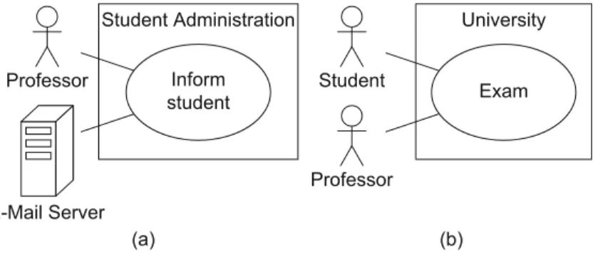
for the execution of use cases. In example (a) inFigure 3.4, the actor Professoris an active actor, whereas the actorE-Mail Serveris passive. However, both are required for the execution of the use caseInform stu-dent. Furthermore, use case diagrams can also contain bothprimaryand
secondaryactors, also shown in this example. A primary actor takes an actual benefit from the execution of the use case (in our example this is theProfessor), whereas the the secondary actorE-Mail Serverreceives no direct benefit from the execution of the use case. As we can see in example (b) inFigure 3.4, the secondary actor does not necessarily have to be passive. Both theProfessorand theStudentare actively involved in the execution of the use caseExam, whereby the main beneficiary is the Student. In contrast, theProfessorhas a lower benefit from the exam but is necessary for the execution of the use case. Graphically, there is no differentiation between primary and secondary actors, between active and passive actors, and between human and non-human actors.
Figure 3.4 Examples of actors
(a) (b)
University Exam Student
Professor Student Administration
Inform student
E-Mail Server Professor
imple-mented or serves as an actor. In example (a) inFigure 3.4, theE-Mail Serveris an actor—it is not part of the system but it is necessary for the execution of the use caseInform student. However, if no external server is required to execute this use case because the student administration system implements the e-mail functionality itself or has its own server, theE-Mail Serveris no longer an actor. In that case, only theProfessoris required to inform students about various news items.
3.3 Associations
In the examples inFigure 3.4, we connected the actors with use cases via solid lines without explaining this in more detail. An actor is connected
with the use cases viaassociationswhich express that the actor com- Association
A X
municates with the system and uses a certain functionality. Every actor must communicate with at least one use case. Otherwise, we would have an actor that does not interact with the system. In the same way, every use case must be in a relationship with at least one actor. If this were not the case, we would have modeled a functionality that is not used by anyone and is therefore irrelevant.
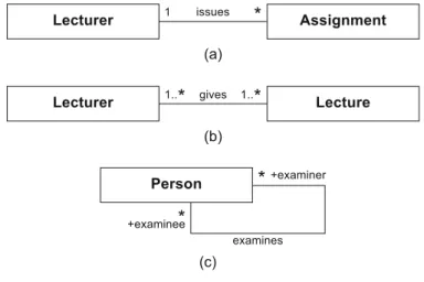
An association is always binary, meaning that it is always specified between one use case and one actor. Multiplicities may be specified for the association ends. If a multiplicity greater than 1 is specified for the actor’s association end, this means that more than one instance of an actor is involved in the execution of the use case. If we look at the example inFigure 3.5, one to three students and precisely one assistant is involved in the execution of the use case Conduct oral exam. If no multiplicity is specified for the actor’s association end, 1 is assumed as the default value. The multiplicity at the use case’s association end is mostly unrestricted and is therefore only rarely specified explicitly.
1..3
Laboratory Assignment Conduct oral exam
Assistant
Student
Actors do not represent a specific user—they represent roles that Role
users adopt. If a user has adopted the respective role, this user is autho-rized to execute the use cases associated with this role. Specific users can adopt and set aside multiple roles simultaneously. For example, a person can be involved in the submission of a certain assignment as an assistant and in another assignment as a student. The role concept is also used in other types of UML diagrams, such as the class diagram (see Chapter 4), the sequence diagram (see Chapter 6), and the activity diagram (see Chapter 7).
3.4 Relationships between Actors
Actors often have common properties and some use cases can be used Synonyms:
• Generalization • Inheritance
Generalization for actors
X
Y
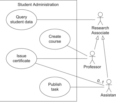
by various actors. For example, it is possible that not only professors but also assistants (i.e., the entire research personnel) are permitted to view student data. To express this, actors may be depicted in an inher-itance relationship(generalization) with one another. When an actorY (sub-actor) inherits from an actorX(super-actor),Yis involved with all use cases with whichXis involved. In simple terms, generalization ex-presses an “is a” relationship. It is represented with a line from the
sub-Figure 3.6
Example of generalization for actors
Student Administration
Query student data
Issue certificate
Create course
0..1 Professor
Research Associate
Assistant Publish
actor to the actor with a large triangular arrowhead at the super-actor end. In the example inFigure 3.6, the actorsProfessorand Assis-tantinherit from the actorResearch Associate, which means that every professor and every assistant is a research associate. Every research as-sociate can execute the use caseQuery student data. Only professors can create a new course (use caseCreate course); in contrast, tasks can only be published by assistants (use casePublish task). To execute the use caseIssue certificateinFigure 3.6, an actorProfessoris required; in ad-dition, an actorAssistantcan be involved optionally, which is expressed by the multiplicity0..1.
There is a great difference between two actors participating in a use case themselves and two actors having a common super-actor that par-ticipates in the use case. In the first case, both actors must participate in the use case (seeFig. 3.7(a)); in the second case, each of them inherits the association. Then each actor participates in the use case individually (seeFig. 3.7(b)).
Student Administration
Query student data Professor
Assistant
(a) (b)
Student Administration
Query student data {abstract}
Research Associate
Professor Assistant
Figure 3.7
Example with and without generalization
If there is no instance of an actor, this actor can be labeled with the
keyword{abstract}. Alternatively, the names of abstract actors can be Abstract actor represented in italic font. The actorResearch AssociateinFigure 3.7(b)
is an example of an abstract actor. It is required to express that either a Professoror anAssistantis involved in the use caseQuery student data. The use of abstract actors only makes sense in the context of an inheri-tance relationship: the common properties of the sub-actors are grouped and described at one point, namely with the common, abstract super-actor.
3.5 Relationships between Use Cases
Up to this point, we have learned only about relationships between use cases and actors (associations) and between actors themselves (general-ization of actors). Use cases can also be in a relationship with other use cases. Here we differentiate between«include»relationships,«extend» relationships, and generalizations of use cases.
Figure 3.8
Example of«include»and «extend»
Student Administration Reserve lecture hall Announce
lecture
Assign lecturer
«include » «extend
»
Professor
If a use caseAincludes a use caseB, represented as a dashed arrow «include»
B A
«include
»
fromA toB labeled with the keyword«include», the behavior ofB is integrated into the behavior ofA. Here,Ais referred to as thebase use caseandBas theincluded use case. The base use case always requires the behavior of the included use case to be able to offer its functional-ity. In contrast, the included use case can be executed on its own. The use of «include» is analogous to calling a subroutine in a procedural programming language. In the use case diagram inFigure 3.8, the use casesAnnounce lectureandAssign lecturerare in an«include» relation-ship, wherebyAnnounce lectureis the base use case. Therefore, when-ever a new lecture is announced, the use caseAssign lecturermust also be executed. The actorProfessoris involved in the execution of both use cases. Further lecturers can also be assigned to an existing lecture as the included use case can be executed independently of the base use case. One use case may include multiple other use cases. One use case may also be included by multiple different use cases. In such situations, it is important to ensure that no cycle arises.
Ais again referred to as thebase use caseandBas theextending use
case. An«extend»relationship is shown with a dashed arrow from the «extend»
B A
«extend
» extending use caseBto the base use caseA. Both use cases can also be
executed independently of one another. If we look at the example in Fig-ure 3.8, the two use casesAnnounce lectureandReserve lecture hallare in an«extend»relationship. When a new lecture is announced, it is pos-sible (but not mandatory) to reserve a lecture hall. A use case can act as an extending use case several times or can itself be extended by several use cases. Again, no cycles may arise. Note that the arrow indicating an«extend»relationship points towards the base use case, whereas the arrow indicating an«include»relationship originates from the base use case and points towards the included use case.
Aconditionthat must be fulfilled for the base use case to insert the Condition behavior of the extending use case can be specified for every«extend»
relationship. The condition is specified, within curly brackets, in a note that is connected with the corresponding«extend»relationship. A con-dition is indicated by the preceding keywordConditionfollowed by a colon. Two examples are shown inFigure 3.9. Within the context of the use caseAnnounce lecture, a lecture hall can only be reserved if it is free. Furthermore, an exam can only be created if the required data has been entered.
By usingextension points, you can define the point at which the be- Extension point havior of the extending use cases must be inserted in the base use case.
The extension points are written directly within the use case, as illus-trated in the use caseAnnounce lecture in the example inFigure 3.9. Within the use case symbol, the extension points have a separate
sec-Student Administration
Reserve lecture hall Announce lecture
Announce exam Condition:
{Lecture hall free} Extension point: Select lecture hall
Condition: {Data entered} Extension point: Enter exam extension points:
Enter exam Select lecture hall
Professor
«extend»
«extend
»
Figure 3.9
tion that is identified by the keywordextension points. If a use case has multiple extension points, these can be assigned to the corresponding «extend»relationship via specification in a note similarly to a condition. In the same way as for actors,generalizationis also possible between Generalization for use
cases
B A
use cases. Thus, common properties and common behavior of different use cases can be grouped in a parent use case. If a use caseAgeneralizes a use caseB,Binherits the behavior ofA, whichBcan either extend or overwrite. Then,Balso inherits all relationships fromA. Therefore, B adopts the basic functionality ofAbut decides itself what part ofAis executed or changed. If a use case is labeled{abstract}, it cannot be ex-ecuted directly; only the specific use cases that inherit from the abstract use case are executable.
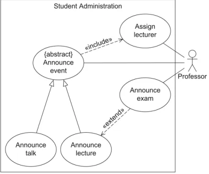
The use case diagram inFigure 3.10shows an example of the gen-eralization of use cases. The abstract use caseAnnounce eventpasses on its properties and behavior to the use casesAnnounce lectureand An-nounce talk. As a result of an«include»relationship, both use cases must execute the behavior of the use caseAssign lecturer. When a lecture is announced, an exam can also be announced at the same time. Both use cases inherit the relationship from the use caseAnnounce eventto the actorProfessor. Thus, all use cases are connected to at least one actor, the prerequisite previously stipulated for correct use case diagrams.
Figure 3.10
Example of generalization of use cases
Student Administration
Assign lecturer {abstract}
Announce event
Announce exam
«include »
Announce talk
Announce lecture
Professor
Generalization allows us to group the common features of the two use casesAnnounce lectureandAnnounce talk. This means that we do not have to model both the «include»relationship and the association with the professor twice.
3.6 Examples of Relationships
To explain again explicitly how the different relationship types in a use case diagram interact with one another, let us take a look at the use case diagram fromFigure 3.11and discuss some interesting cases that occur here.
J
O
L
N M
B C
F H
E
A
G I
D
S
«extend»
«extend » «include
» «include
»
Figure 3.11
Examples of relationships in a use case diagram
• The use caseAincludes the use casesEandD.An actorOis involved in all three use cases. There is no specification of whether this is the same user or different users, that is, different instances ofO. • The use caseHinherits from the use caseC.As use caseCis executed
• The use caseJinherits from the use caseB.As a result of the
inheri-tance relationship, an actorOis involved in the execution of use case J. However, an association withOis also modeled forJdirectly. The consequence of this is that two actors in the roleOare involved in the execution ofJ. Note that these two actors can coincide.
• The use caseFinherits from the use caseG.As a result of the in-heritance relationship, an actorNis involved in the execution of use caseF. ForF, an association with the actorLis also modeled directly. Therefore, an actorNand, due to the inheritance relationship of the actorsL,N, andM, either an actorLor an actorMor an additional ac-torNis involved in the execution ofF. If two actorsNare involved, they may coincide.
• The use caseIextends the use caseF.As use caseFinherits from use caseGand asIextends use caseG, this relationship is passed on toF. IfGandIwere in an«include»relationship, this relationship would also be passed on toFin the same way.
• The use caseJextends the use caseH.This is as a result of the
inher-itance relationships fromBtoJand fromCtoH.
3.7 Creating a Use Case Diagram
So, how do you create a use case diagram? First you must identify ac-tors and use cases and then place them in relationships with one another. You then describe the use cases in detail. At first glance, this diagram seems to be simple due to the low number of concepts involved. But in fact, use case diagrams are often created incorrectly with a lot of errors. Therefore, here we take a brief look at the principles of creating use cases. For details, see the extensive literature on requirements engineer-ing, for example [16, 30, 40]. We then explain some typical pitfalls to be avoided when modeling use case diagrams.
3.7.1 Identifying Actors and Use Cases
According to [30], there are two ways to identify use cases for prospec-tive system design:
1. Analysis of requirements documents 2. Analysis of the expectations of future users
![Figure 2.1 shows a taxonomy of the 14 UML diagrams [35], giv- giv-ing a very rough categorization](https://thumb-eu.123doks.com/thumbv2/123dok_br/16343322.721136/27.714.78.499.303.687/figure-shows-taxonomy-uml-diagrams-giv-rough-categorization.webp)