ISSN 1549-3636
© 2010 Science Publications
Corresponding Author: Rafa E. Al-Qutaish, Department of Software Engineering, Alzaytoonah University of Jordan, Airport Street, Amman 11733
UML Diagrams Generator: A New CASE Tool to Construct the Use-Case
and Class Diagrams from an Event Table
Mohammad I. Muhairat, Rafa E. Al-Qutaish and Akram A. Abdelqader
Department of Software Engineering, Alzaytoonah University of Jordan,
Airport Street, Amman 11733, Jordan
Abstract: Problem statement: Building UML diagrams is a very important and time consuming task for both requirements and design phases. However, some of these diagrams, such as use-case and class diagrams can be considered as a transition between the two phases. Approach: Through this study, the event table will be used to derive the use-case and class diagrams. Results: A new CASE tool to automate the proposed approach will be introduced, that is, the UML diagrams generator (UMLdg). Conclusion: It is clearly noted that the proposed CASE tool (UMLdg) gives an ideal and reasonable methodology to construct the intended use-case and class diagrams from any comprehensive event table. Furthermore, this tool will save the time for the building process of such diagrams.
Key words: Requirements specification, software design, CASE tool, UML, use-case diagram, class diagram
INTRODUCTION
Nowadays, there are many different techniques (approaches) to identify the use-cases, for examples:
• Listing of all users and define their needs (Bennett et al., 2005; Larman, 2004; Liang, 2003; Reed, 2001; Schach, 2003)
• Defining all system functions and adding new functions that user may be need (Bennett et al., 2005; Larman, 2004; Reed, 2001; Satzinger et al., 2004; Schach, 2003)
• List all Graphical User Interfaces that may be used by users (Cockburn, 2000; Larman, 2004)
• Defining of all users’ goals in using the system (Chung and Supakkul, 2004; Larman, 2004; Lee and Xue, 1999; Liang, 2003; Satzinger et al., 2004)
Many analysts used the fourth approach to get an initial list of use-cases. However, the most used approach for defining a use-case model is event decomposition technique (Larman, 2004; Reed, 2001; Satzinger et al., 2004). This technique focusing on events a system must respond to and looking at how a system responds.
An event is an occurrence at specific time and place, can be described and should be remembered by the system (Larman, 2004; Reed, 2001; Satzinger et al., 2004).
Building the use-case and class diagrams is a very important task since it represents a transition between the requirements and design phases. However, building such diagrams is a time consuming process and needs a complete understanding of the requirements. In this paper, we introduce an approach to derive the use-case and class diagrams from an event table. In addition, a new CASE tool for automating the new approach will be discussed. The new approach with the new CASE tool will facilitate and speed the generation process of these diagrams. Taking into account that this approach will completely depend on the availability of a comprehensive event table which to be built from the available requirements.
MATERIALS AND METHODS
and Heitmeyer (1999) to generate a suite test sequences. Moreover, Snoeck and Dedene (2001) have proposed a new form of event table called object-event table to be a useful technique for modeling interaction between domain object types.
Business modeling help analyst to understand the business process. As result of that modeling, business events are identified and documented in an event table. Event table is a list of actions that lists events in rows and the information about each event in columns. Analyst can use event table to define use-case model and domain class model. However, analyst has to make some decisions when building a use-case model. The first one is to combined business events into one use-case. For example, the business events of adding, deleting, updating customer information, analyst can combined them in one use-case, that is, Maintain Customer Information. Also, analyst makes decisions to split one business event into multiple use-cases. For example, the business event customer withdraws his cash, analyst can split it to two use-cases, that is, Withdraw Cash and Identify Customer and he can identify the relationship between them, for example; Withdraw Cash<<include>>Identify Customer.
As a result of this splitting, the traditional event table contains the following core elements (columns):
• Event: An event which causes the system to do something
• Source: The source of an event (an actor for an EE and the system for a TIE and CIE)
• Action: The system functionality which we need • Object: The object affected by this action
For the purpose of building a complete use-case model and domain class model, we need to extend the traditional table and make some modification to contain other elements, as the following:
• Input message: For external events, the message is data entering the system and for internal events, the message is reaching point in time (timer) that makes the system process
• General source or special source: It is the type of an event source which is used to define a generalization/specialization relationship between sources
• Output message: It is the output which is produced by the system, if exist
• Includes: Which is used to determine the existence of includes relationship between actions
• Extends: Which is used to determine the existence of extends relationship between actions
• Specializes: Which is used to determine the existence of specializes relationship between actions
• Destination: It is an actor which receives the result of an event execution
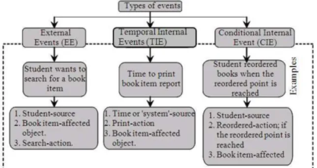
Figure 1 illustrates the three types of events along with examples. However, there are three types of events, that is:
• External Events (EE): An event that occurs outside of the system, usually initiated by external actor or user
• Temporal Internal Events (TIE): An event that happens when the system reaches a specific point in time
• Conditional Internal Events (CIE): An event occurs when something happens inside the system and the system must initiate some process to response for this event
Use-case diagram: The system or subsystem behaviors can be captured by the use-case diagram. However, the use-case diagram represents the interaction between the actors and some functionality (called use-cases). An actor may be an external person, another software system, a hardware device, or process interacting with the system, subsystem or class to achieve a useful goal (Boggs and Boggs, 2002; Rumbaugh et al., 2004). Actors can participate with one or more use-cases via exchanging messages.
An abstract actor description is shared and augmented by one or more specific actor descriptions, that is, an actor can be defined in generalization hierarchy.
An actor is denoted as a small stick person with the name below it. An use-case is a consistent unit of externally visible functionality provided by a classifier (called the subject) and expressed by sequences of messages exchanged by the subject and one or more actors of the system unit (Boggs and Boggs, 2002; Rumbaugh et al., 2004). In addition to association with actors, a use-case can participate in several relationships; Table 1 for the details of these relationships.
Class diagram: A class can be used to represent a discrete concept within the application being modeled in order demonstrate things of a particular kind (Rumbaugh et al., 2004). Also, a class shows a set of objects with similar structure, behavior and relationships. Every class contains a set of attributes along with the related operations. In addition, a class defines a set of objects that have states and behaviors. The State is described by attributes and associations.
Table 1: Use-case relationships
Relationship Function Notation
Association To indicate the communication between actors and use-cases.
Extend To indicate the insertion of additional << extends>> behavior into a base use-case.
Include To describe a behavior that is inserted <<includes>> explicitly into a base use-case.
Use-case To indicate the communication between a generalization features to it. General use-case with more
specific use-case that inherits and adds
Table 2: Class relationships
Relationship Function Notation
Association A connection between objects or classes Dependency A relationship between two model
elements (class, package)
Generalization A relationship between more specific and more general classes
Realization Relationship between a specification and its implementation (interface, class)
Usage Represents that one element requires <<kind>> another element for its functioning
Fig. 2: Example of class notation
Attributes are generally used for pure data values without identity, such as numbers and strings and associations are used for connections among objects with identity. Whereas, the behaviors are described by a set of operations; a method (or function in C++) is the implementation of an operation. The notation for a class is a rectangle with sections for the name of the class, attributes and operations, as shown in Fig. 2.
Relationships among class diagram are association, generalization and various kinds of dependency, including realization and usage, as shown in Table 2.
RESULTS
Deriving the use-case diagram: This process consists of five steps a use-case diagram, that is:
• Identify the actors for each event or action from the sources and destinations
• Identify the relationships between actors, if exists. There is only one type of relationship between actors, that is, a generalization/specialization relationship
• Identify the use-cases. The analyst can derive the use-case from the action which proceeded by an actor
• Identify the relationships between use-cases, if exists. As we mentioned above, there is three type of relationships between use-cases (includes, extends and use-case generalization)
• Integrate all use-cases and actors with all relationships types in one use-case diagram
From a given event table we can map the use-cases and the actors, as in Fig. 3.
However, this mapping could be implemented using the two types of events, that is, External Event (EE) and Internal Event (TIE, CIE). Figure 4 and 5 illustrate examples of both types, respectively.
Fig. 4: Example of mapping a use-case and actor from an EE
Fig. 5: Example of mapping a use-case and actor from a TIE and CIE
Deriving the class diagram: This process consists of the following five steps to build a class diagram: • Identify the classes for each event or action from
the sources and objects
• Identify the relationships between sources and objects, if exists. There are many types of relationships between classes as mentioned above in Table 2. Our application, by default, will generate association relationship with 1…n multiplicity and the analyst will change it manually by necessity
• Identify the attributes. The analyst can derive the attributes from t he input and output messages Also, the input messages can be used to define a method parameters list and the output messages can be used to define a method return values • Identify operations which can be directly derived
from an action. Also, in event table, we will write all actions in an uncomplicated way. For example, (create, search, cancel) not (maintain) which consist of (create, update and delete)
• Integrate all classes with all relationships types in one class diagram
From a given event table we can map the classes, attributes, operations with their parameter list and return values, as in Fig. 6.
Fig. 6: Mapping a class diagram from an event table
Fig. 7: Example of mapping a class diagram from an EE
Fig. 8: Example of mapping a class diagram from a TIE and CIE
However, this mapping could be implemented using the two types of events, that is, External Event (EE) and Internal Event (TIE, CIE). Figure 7 and 8 illustrate examples of both types, respectively.
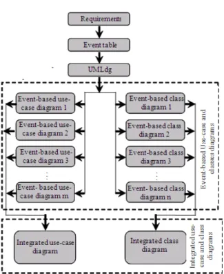
Fig. 9: The UMLdg inputs and outputs
Fig. 10: Snapshot of the UMLdg main screen
The UMLdg CASE tool has been built to generate the use-case and class diagrams using the entered event table. However, this new CASE tool contains the following features (functionalities), Fig. 10:
• Build events table
• Build event based use-case diagram • Generate use-case diagram • Build event based class diagram • Generate class diagram
Fig. 11: Snapshot of the ‘build event table’ screen
To build an event table, we need to enter all the elements of each event as the following: event, input message, general source, special source, action, object, output message, includes action, extends action, specialization action and destination; Fig. 11. For the details of these elements refer to materials and methods section above.
After the event table has been completely entered, the other features can be used. However, the ‘build event based use-case diagram’ button will produce the related use-case(s), actor(s) and relationship(s) for each event and the ‘build event based class diagram’ button will produce the related class(s) for each event. Furthermore, the ‘generate use-case diagram’ and ‘generate class diagram’ will produce the integrated use-case diagram and class diagram for the whole event table, respectively.
DISCUSSION
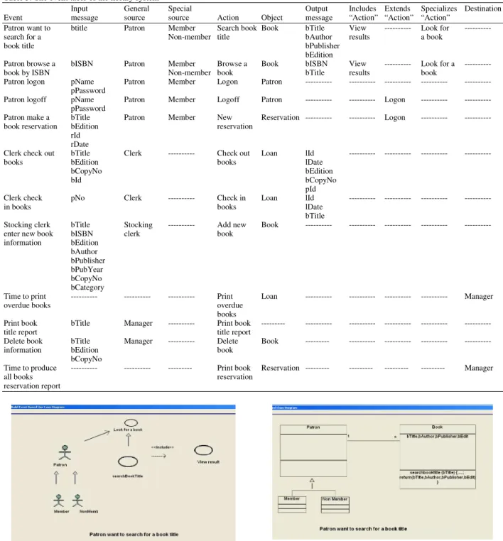
As an example, suppose we have an event table which has been entered to the new UML diagrams generator (UMLdg) CASE tool, Table 3 contains the list of events that are related to the library system.
After the event table has been completely entered to the UMLdg tool, we can select the first features, that is, ‘build event based use case diagram’ to build the use-case diagram which is related to the ‘patron wants to search for a book title’ event (the first event in Table 3). Figure 12 shows the resulted event based use-case diagram.
Table 3: The event table of the library system
Input General Special Output Includes Extends Specializes Destination Event message source source Action Object message “Action” “Action” “Action”
Patron want to btitle Patron Member Search book Book bTitle View --- Look for ---
search for a Non-member title bAuthor results a book
book title bPublisher
bEdition
Patron browse a bISBN Patron Member Browse a Book bISBN View --- Look for a ---
book by ISBN Non-member book bTitle results book
Patron logon pName Patron Member Logon Patron --- --- --- --- --- pPassword
Patron logoff pName Patron Member Logoff Patron --- --- Logon --- --- pPassword
Patron make a bTitle Patron Member New Reservation --- --- Logon --- --- book reservation bEdition reservation
rId rDate
Clerk check out bTitle Clerk --- Check out Loan lId --- --- --- ---
books bEdition books lDate
bCopyNo bEdition
bId bCopyNo
pId
Clerk check pNo Clerk --- Check in Loan lId --- --- --- ---
in books books lDate
bTitle
Stocking clerk bTitle Stocking --- Add new Book --- --- --- --- --- enter new book bISBN clerk book
information bEdition bAuthor bPublisher bPubYear bCopyNo bCategory
Time to print --- --- --- Print Loan --- --- --- --- Manager
overdue books overdue
books
Print book bTitle Manager --- Print book --- --- --- --- --- ---
title report title report
Delete book bTitle Manager --- Delete Book --- --- --- --- ---
information bEdition book
bCopyNo
Time to produce --- --- --- Print book Reservation --- --- --- --- Manager
all books reservation
reservation report
Fig. 12: Snapshot of the resulting event-based use-case diagram for the patron wants to search for a book title’ event
Figure 13 shows the resulted event-based class diagram. Furthermore, selecting the ‘build use-case diagram’ and ‘build class diagram’ features of the UMLdg will give
Fig. 13: Snapshot of the resulting event-based class diagram for the ‘patron wants to search for a book title’ event
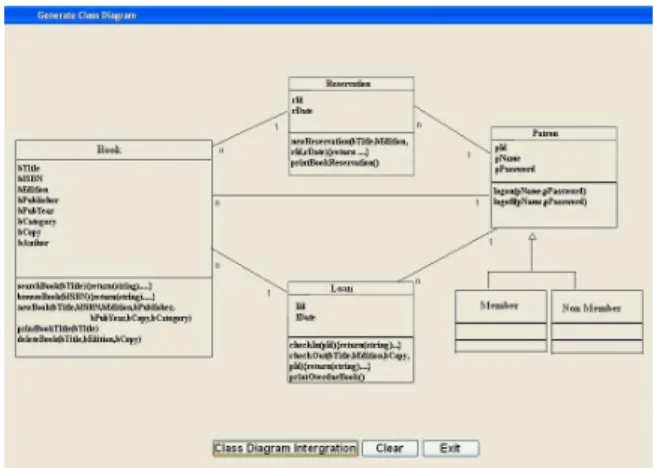
Fig. 14: Snapshot of the integrated use-case diagram for the library system
Fig. 15: Snapshot of the integrated class diagram for the library system
CONCLUSION
Constructing the use-case and class diagrams is a very important and essential task to go ahead to the design process. However, the use-case and class diagrams represent a transition stage between the requirements and design phases. Furthermore, building such diagrams is a time consuming task and needs a complete understanding of the user requirements. In this paper, we have introduced an approach to derive the use-case and class diagrams from an event table. This new approach will facilitate and speed up the generation process of the use-case and class diagrams. However, this approach is completely depending on the availability of a comprehensive event table which should be built from the available user requirements during very early tasks. In addition, a new CASE tool to implement this approach is introduced, that is, the UML diagrams generator (UMLdg) CASE tool.
It can be clearly noted from the above sections that this approach gives an ideal and reasonable methodology to construct the intended use-case and class diagrams from any comprehensive event table. Furthermore, the UMLdg CASE tool will save the time for the building process of the use-case diagram.
As a future research, this approach could be extended in order to generate other UML diagrams such as activity diagram and sequence diagram. Moreover, the CASE tool could be extended to include these diagrams.
REFERENCES
Bennett, S., S. Mcrobb and R. Farmer, 2005. Object-Oriented Systems Analysis and Design Using UML. 3rd Edn., McGraw Hill Education, USA., ISBN: 978-0077110000, pp: 624.
Boggs, W. and M. Boggs, 2002. Mastering UML with Rational Rose. 1st Edn., SYBEX Inc., USA., ISBN: 978-0782140170, pp: 828.
Chung, L. and S. Supakkul, 2004. Representing NFRs and FRs: A goal-oriented and use case-driven approach. Proceedings of the 2nd International Conference on Software Engineering Research, Management and Applications, May 4-5, Los Angeles, CA., USA., pp: 29-41.
Cockburn, A., 2000. Writing Effective Use Cases. 1st Edn., Addison-Wesley, Boston, MA., USA., ISBN: 978-0201702255, pp: 304.
Gargantini, A. and C. Heitmeyer, 1999. Using model checking to generate tests from requirements specifications. ACM SIGSOFT Software Eng. Notes, 24: 146-162. DOI: 10.1145/318774.318939 Larman, C., 2004. Applying UML and patterns: An
Introduction to Object Oriented Analysis and Design and Iterative Development. 3rd Edn., Prentice Hall, USA., ISBN: 978-0131489066, pp: 736.
Lee, J. and N. Xue, 1999. Analyzing user requirements by use cases: A goal-driven approach. IEEE, Software, 16: 92-101. DOI: 10.1109/52.776956 Liang, Y., 2003. From use cases to classes: A way of
building object model with UML. J. Inform. Software Technol., 45: 83-93. DOI: 10.1016/S0950-5849(02)00164-7
McMenamin, S.M. and J.F. Palmer, 1984. Essential Systems Analysis. 1st Edn., Yourdon Press, New York, USA., ISBN: 978-0917072307 pp: 408. Page-Jones, M., 1999. Fundamentals of
Purhonen, A., 2002. Quality Driven Multimode DSP Software Architecture Development. 1st Edn., Julkaisija-Utgivare Publisher, Oulu, Finland, ISBN: 951-38-6005-1, pp: 154.
Reed, P.R., 2001. Developing Applications with Java and UML. 1st Edn., Addison Wesley, Boston, MA., USA., ISBN: 978-0201702521, pp: 504. Rumbaugh, J., I. Jacobson and G. Booch, 2004. The
Unified Modeling Language Reference Manual. 2nd Edn., Wesley, Boston, MA., USA., ISBN: 978-0321245625, pp: 752.
Satzinger, J.W., R.B. Jackson and S.D. Burd, 2004. Object-Oriented Analysis and Design with the Unified Process. 1st Edn., Thomson Course Technology, Cengage Learning, Florence, KY., USA., ISBN: 978-0619216436, pp: 608.
Schach, S.R., 2003. An Introduction to Object-Oriented System Analysis and Design with UML and Unified Process. 1st Edn., McGraw-Hill, USA., ISBN: 978-0071215107, pp: 395.
Snoeck, M. and G. Dedene, 2001. Core modelling concepts in object-oriented conceptual modeling. Proceeding of the 38th Technology of Object-Oriented Languages and Systems Conference, Mar. 12-14, Zurich, Switzerland, pp: 170-179. DOI: 10.1109/TOOLS.2001.911769
Stumpf, R. and L. Teague, 2005. Teachings object-oriented system analysis and design with UML. Proceedings of the Information Systems Education Conference (ISECON’05), October 6-9, Columbus,
OH, USA., pp: 1-14.
http://www.csupomona.edu/~rvstumpf/isecon/teac hing_OO.ppt