Abstract—Springback is a very important factor to influence
the quality of sheet metal forming. Accurate prediction and controlling of springback is essential for the design of tools for sheet metal forming. Several approaches have been proposed for springback compensation by modification of the tooling shape. These approaches are iterative finite element methods. In this paper an analytical approach is presented for one step modification of the tooling shape in channel forming process to compensate the springback error. With the help of this approach, the optimum die shape for producing the target shape can be obtained in a few seconds. The algorithm of springback compensation by inverse FE modelling is also presented. The results of the analytical approach coincide with those of FE approach. The accuracy of the obtained results is verified by the experimental results and high precision is achieved.
Index Terms—Analytical approach, Channel forming, Die design, Finite element method, Springback
I. INTRODUCTION
Channel forming is a common forming way of many sheet metals such as automotive panels, electronic components and devices. By applying this method, the quick and efficient mass production can be achieved.
The springback is mainly an elastic deformation which occurs after sheet metal forming processes, when the formed part is removed from the forming tools. The springback changes the part’s geometry so it can cause difficulties during a subsequent assembly process, or cause the twisting in the assembled part. An accurate prediction of springback of formed sheets is of vital importance for the design of tools in automotive and aircraft industries.
Introducing Df, Dl and Dsb as total displacement, loading displacement and springback displacement, respectively we have:
sb l
f D D
D = + (1)
Loading deformation (Dl) usually can be obtained from geometry and configuration of the die components. Unloading deformation (Dsb) is influenced by a combination of various process parameters such as tool shape and dimensions, contact friction condition, material properties, thickness, etc. [1].
The final product of forming process should be close
1.PhD Student, Mechanical Engineering Department, Amirkabir University of Technology, Tehran, Iran (e-mail: [email protected]).
2.Associate Professor, Mechanical Engineering Department, AmirKabir University of Technology, Tehran, Iran (e-mail: [email protected]). 3.Professor, Mechanical Engineering Department, AmirKabir University of
Technology, Tehran, Iran(e-mail: [email protected]).
enough to the desired part shape. If the allowable deviation of part shape is defined by , the following relationship should be satisfied:
ξ ≤ − t
f D
D (2)
where Dt is the total deformation in the target process. To satisfy equation (2), the unloading deformation should be vanished or compensated.
Several researches have been performed for decreasing the amount of springback by increasing sheet tension during forming process.
Liu [2] has proposed a method to reduce springback using different histories of restraining force during forming. In this approach, the in-process variation of binder force can provide tensile pre-loading or post loading on the formed part in order to significantly reduce springback. However, a tight control during production is required, making this process sensitive to any variations in manufacturing conditions such as friction coefficient. Sunseri et al. [3]developed and implemented a closed-loop algorithm for binder force control to make the forming process more robust and repeatable. In their strategy, a punch force trajectory is introduced as the target curve instead of using a binder force trajectory.
The tooling shape is not required to be modified in these approaches but a control system for adjusting the binder force is needed. Also increasing the binder force can cause tearing of sheet in many cases. Therefore the applications of such approaches are limited and costly.
In another group of researches, the springback deformation is compensated by modifying the shape of the forming tools. It is very important to predict the springback and correct it at the tool design stage, since the geometry correction on the finished tools is very expensive and time-consuming.
In this group, iterative algorithms have been proposed for modifying the tooling shape to compensate springback error. For prediction of springback in these researches, incremental finite element method is used.
Karafillis and Boyce [4] proposed the “Force Descriptor method (FDM)”. In their approach the springback deformation is inversely modeled in each iteration, by applying the internal forces on the target geometry. Therefore the modified tooling shape in each iteration can be obtained from following equation:
) isb( t )
l( D D
D i+1 = + i (3)
Where Disb(i) is the inverse springback deformation.
Anagnostou [5] proposed a modified FDM method with higher convergence rate. He defined a multiplier for internal force vector that can decrease the number of iterations.
A One-step Analytical Approach for Springback
Compensation in Channel Forming Process
Wagoner et al. [6,7] developed the “displacement adjustment method DA”. In DA method, a flat sheet of metal is deformed to a trial die shape (for the first cycle, the trial die shape is the target part shape). After springback, the shape in the last iteration is compared with its target. The shape error is defined as the vector of y coordinates of the target less the y coordinates of the springback shape for the last iteration. In the next step, the amount of shape error is added to the current die shape. A new tooling shape will be obtained. For the next iteration, a flat sheet is deformed to the new trial die shape. If the springback shape is not the same as the target, another iteration will be conducted until the specified tolerance is achieved.
Some other approaches have been presented for modifying the tool shape to compensate the springback error with the help of finite element method [8-12]. These approaches are applicable for a wide range of processes. However, an enormous amount of time and cost is needed for the process design by FEM.
Analytical methods for process analysis are time-saving but can only be used for simple problems. Vin et al. represented an analytical model to evaluate the springback and punch displacement in the air V-bending process [13]. They investigated the influence of changing Young’s modulus on the springback. Zhang et al. developed a mathematical model for predicting the sheet springback of U-bending [14]. They investigated the effect of blank holding force and several material hardening models on the sheet springback. Kim et al.
proposed an analytical model to calculate the bend allowance and the springback in the air V-bending process [15]. They assumed plane-strain condition and used Swift’s material model to represent strain-hardening behavior. The shift of neutral axis is considered in their model. Leu et al.
investigated the influence of coining force on the springback reduction in the V-bending process by their analytical model [16].
In the present work, an analytical approach is proposed to compensate springback error for an arbitrary channel forming process. The springback deformation can inversely be obtained from the target shape in one step. Therefore the modified tooling shape for producing the target shape can be defined by this approach in a few seconds.
II. ANALYSIS OF CHANNEL FORMING
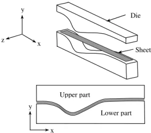
The tooling geometry for the asymmetric channel forming is shown in Fig. 1. The main objective of this section is to determine the springback deformation of a fully loaded sheet analytically. The shape of the fully loaded sheet corresponds to the die shape (Fig. 1). The following assumptions are applied in the analysis:
1. The sheet is wide enough relative to its thickness. Therefore the plane strain state is assumed.
2. Planes normal to the sheet surface remain planar during the forming process.
3. Volume conservation is kept during the forming process, so the volume variation due to elastic deformation is neglected, r+ =0.
4. Material behavior is expressed by Swift’s model,
n
K(ε0 ε)
σ = + .
5. Hill’s 48 quadratic yield criterion is used to define the plastic yielding behavior of normal anisotropic material.
6. Geometry of the product is defined by the profile of the sheet middle surface.
The profile of the fully loaded sheet is defined by coordinates of m points:
) , ( ; }
{ = xi yi
= x1,x2,...,xi,...,xm xi
X (4)
Three consecutive points (xi, xi+1, xi+2) are selected in each step (Fig.2). A unique arc, passing through these three points, can be defined. The coordinates of arc center can be calculated as below:
(
) (
)
(
) (
)
2 2 2 2 2 2 2
2 2 2 1 2 1 1
2 2
1 1
2 2
1 1
1 2 2 1 1 2 2 1
1 2 2 1 1 2 2 1
) (
2 ; ) (
2
) (
2 ; ) (
2
. . . .
. . . .
i i i i
i i i i
i i i
i
i i i
i c c
y x y x C
y x y x C
y y B y
y B
x x A x
x A
A B A B A C A C
B A B A B C B C
y x
− − + =
− − + =
− =
− =
− = −
=
− −
− −
=
+ +
+ +
+ +
+ +
(5)
The arc radius and angle can be obtained as:
(
)
2(
)
2c i c i
c x x y y
r = − + − (6)
(
−)
+(
−)
= + +
c
i i i i
r
y y x x
2 Arcsin
2
2 2 2 2
θ
(7)
Figure 2. Springback in a channel arc. Figure 1. Asymmetric Channel Forming.
y
x z
x y
Die
Sheet
Upper part
The arc radius and angle after springback (r’c , ’), can be
calculated by the presented analytical approach in the next section. By constraining the first point (xi), the coordinates of the arc center after springback can be expressed as follows:
(
)(
)
(
′)(
−)
+ + − ′ = ′ ′ i i c c c i i c c c c c y y y r r x x x r r y x (8)The transformed position of the second and third points (due to the sheet springback) can be obtained as below:
′ − ′ − ⋅ ′ + ′ ′ = ′ ′ = ′ ′ − ′ − ⋅ ′ + ′ ′ = ′ ′ = ′ + + + + + + c i c i c c i i c i c i c c i i y y x x y x y x y y x x y x y x ) ( ) 2 ( 2 2 2 1 1 θ θ T x T x i 1 i (9) = θ θ θ θ θ cos sin sin cos ) ( T (10)
The effect of the above transformation on the remaining points can be expressed as:
) 3 ( ) ).(
(∆ − k=i+ ...n
+ ′ =
′k xi+2 T xk xi+2
x θ
(11)
θ θ θ = − ′
∆ (12)
The final sheet geometry can be obtained after springback calculation in the last three points.
III. SPRINGBACK CALCULATION
As it is shown in Fig. 2, the sheet undergoes tension on the outer fibers and compression on the inner ones (Fig. 2). The position of the neutral fiber (stress free fiber rn) changes
continuously during the forming process. The distribution of the tangential strain through thickness is:
n r r ln = θ ε (13)
The following model is applied for the material hardening behavior: ≥ + ≤ = Y n Y for ) K( for E 0 (14)
where ,ε are effective stress and effective strain, respectively. K, 0, n are hardening coefficient, pre-strain and
hardening exponent, respectively. Y is the elastic limit
strain, corresponding to initial yield stress (σY). The force equilibrium yields:
r dr
dσr σθ −σr
= (15)
where , r are tangential and transverse stress,
respectively.
From Hill’s yield criterion,
n r Fσ FK(ε0 ε)
σ
σθ − = = + (16)
The anisotropy coefficient for plane strain condition (F) is defined as: R R F 2 1 1 + + = (17)
where R is transverse anisotropy coefficient.
Based on plastic work formulation, following equation can be written: θ θε σ ε σ ε
σ. = r. r+ . (18)
By applying assumption (3) in the above equation we have:
(
θ)
θθ θ
θ σ ε σ σ ε
ε σ ε
σ. =− r. + . = − r. (19)
According to equation (16), the equivalent strain can be obtained: − ≤ − + ≥ = y n y n t r for r
F
t r for r F θ θ ε ε ε (20) where E r F
ty y n
σ ν ) 1 ( − 2
= is the half thickness of the elastic region.
According to assumption (3), the following equation can be expressed: t r t r V
Vi = f nθ i = cθ (21)
Therefore, i c nt r r
t= (22)
Where t and ti , are the initial and the final sheet
thicknesses, respectively.
By substitution of equation (17) in equation (16) and integrating from r to the outer fiber, following equation can be obtained: ≤ − − = ≥ + = − − + + n t r r n n t r r r n t r r n n t r r r r r r dr r r F FK d r r r dr r r F FK d c c c c )) ln( ( )) ln( ( 2 0 2 2 0 2 ε σ ε σ (23)
r at outer fiber is zero, then r can be obtained as:
≤ − − − − + ≥ + + − + + = + + + + n n n c n n n n n c n n r r r r t r F r r F n K r r r t r F r r F n K ] )) 2 ln( ( )) ln( ( [ 1 ] )) 2 ln( ( )) ln( ( [ 1 1 0 1 0 1 0 1 0 ε ε ε ε σ (24)
From the continuity of transverse stress, the radius of the neutral fiber (rn) can be calculated.
The bending moment can be obtained as:
+ + + − − − + − + + + − + + − − = = 2 0 2 2 0 2 2 )) ln( ( ) ln( 1 )) ln( ( t r t r r n n t r t r n t r t r r n n t r t r c y n y n y n y n c c c rdr r r F FK b rdr r r E b rdr r r F FK b rdr b M σ ε ν σ ε σθ (25)
where b is the sheet width.
The bending radius after springback (r’c) can be calculated
from: 3 2) 1 ( 12 1 1 Ebt M r
rc c
ν − = ′
− (26)
According to fixed length of the neutral fiber, the bending angle after springback ( ’) can be easily calculated.
IV. SPRINGBACK COMPENSATION
The main objective of this section is to find the modified die shape to produce the target shape. To achieve this purpose, n points are selected on the target shape. According to the section II, a unique radius (rti) and angle ( ti) can be
calculated for each three consecutive points (xi, xi+1, xi+2). By assuming roi and oi as the arc radius and arc angle of the
optimum modified die, following equation can be derived from equation (26):
3 2) 1 ( 12 1 1 Ebt M r r o ti oi ν − = − (27)
where bending moment at the optimum die shape (Mo) can
be calculated from equation (25). Therefore equation (27) becomes: + + + − − − + − + + − + − − + + − − − = − = − 2 0 3 2 2 3 2 2 0 3 2 2 2 3 2 )) ln( ( ) 1 ( 12 ) ln( 1 ) 1 ( 12 )) ln( ( ) 1 ( 12 ) 1 ( 12 1 1 t r t r r n n t r t r n t r t r r n n t r t r ti oi oi y n y n y n y n oi oi oi rdr r r F FK Et rdr r r E Et rdr r r F FK Et rdr Et r r σ ε ν ν ν σ ε ν σ ν θ (28)
By numerical solution of the above equation by Newton-Raphson method, the radius of optimum modified die can be evaluated. According to the fixed length of the neutral fiber, the arc angle of the optimum modified die ( oi) can be
easily calculated.
By evaluation of the arc radius and angle of the optimum modified die for [N/2] section of the target shape, the full shape of the optimum modified die shape for producing the target shape can be obtained.
V. SPRINGBACK COMPENSATION BY FEM
In this section an iterative algorithm for springback compensation by inverse FE modelling is presented. By the finite element method, a wide range of forming processes can be analyzed. For the inverse springback analysis, the explicit-implicit FEA approach is applied. For inverse movement of the final product to the fully loaded product, some considerations should be taken into account. To achieve this purpose, the contact loads (between the die and the sheet) at the end of the loading should be applied on the final geometry; the residual stress ( res) at the end of process should
be distributed on the final shape; a proper node (minimum rotation) should be constrained and elastic material property should be defined. The contact forces (Fc) and residual stresses can be obtained from the explicit-implicit modelling of forward analysis. For more details refer to [12].
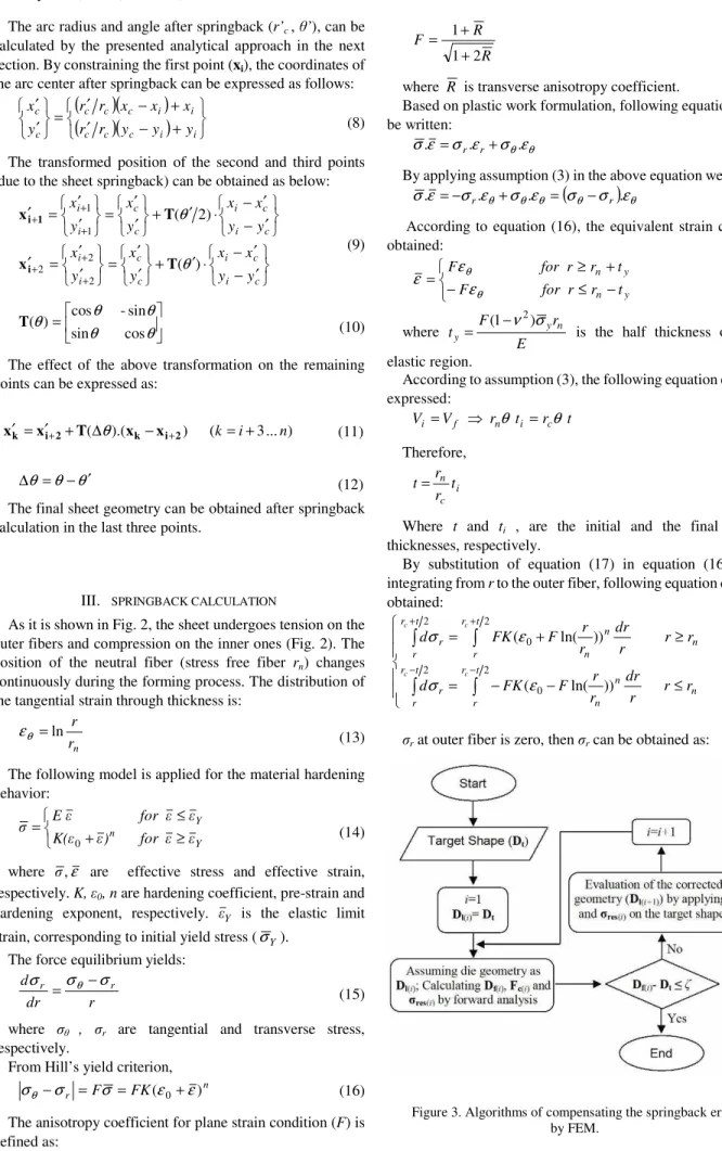
The algorithm for the springback compensation by inverse FE modelling comprises following steps:
The target geometry (Dt) is assumed as the fully loaded geometry (Dl). The forward FE analysis is performed and the contact forces (Fc) at the end of loading and the residual stresses ( res) at the end of process are saved.
1. The target geometry (Dt) is assumed as the final geometry (Df). The inverse FE analysis is performed by applying the saved data in step 1. Therefore the inverse springback deformation (Disb) is evaluated and the fully loaded geometry (Dl) can be obtained from equation (4). 2. The obtained geometry in step 2 is assumed as the corrected die shape. Forward FE analysis is performed and the contact forces (Fc) at the end of loading and the residual stresses ( res) at the end of process are saved.
3. The obtained final shape in the previous step is compared with the target shape.
4. If the difference is greater than the allowable tolerance ( ), the step 2 should be repeated by applying the saved data in step 3.
The above algorithm is shown in Fig. 3.
VI. RESULTS
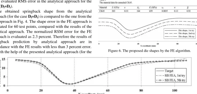
profiles. The gap between the die parts at the end of loading state is set to the sheet thickness. The asymmetric channel forming is performed on the annealed CK45 sheet. The sheet dimension is 115 mm in length, 25 mm in width and 1mm in thickness. Four nodes shell elements are used to mesh the work piece in the FE analysis. The stress-strain curve for the FE analysis is defined corresponding to the obtained stress-strain curve from the performed tension tests on the applied sheet. The material data are summarized in Table 1. To compare the results, the normalized root mean square shape error (RMS) is calculated for the analytical and FE approach. The normalized RSM error is defined as:
100
0 1
2
× = =
R N y R
N
j j
N (29)
where RN, yj and N are the normalized RMS, the shape error
of the jth point and the number of test points respectively. R0
is the evaluated RMS error in the analytical approach for the case (Dl=Dt).
The obtained springback shape from the analytical approach (for the case Dl=Dt) is compared to the one from the FE approach in Fig. 4. The shape error in the FE approach is evaluated for 60 test points, compared with the results of the analytical approach. The normalized RSM error for the FE approach is evaluated as 2.3 percent. Therefore the results of springback prediction by analytical approach are in accordance with the FE results with less than 3 percent error. With the help of the presented analytical approach (for the
springback compensation) in section IV, the optimum modified die geometry is calculated. The target shape and the obtained optimum die shape by the analytical approach are shown in Fig. 5. This optimum shape is found in one step analytical calculation after a few seconds. The obtained product shape from the optimum die profile matches to the target shape exactly.
The compensation algorithm by the inverse FE analysis is applied to find the optimum die shape. The normalized RSM error of 5 percent is considered as the convergence criteria for this algorithm. The FE algorithm yields the springback shape with the normalized RSM as 4.6 percent error in the fifth iteration. The proposed die geometry for the first, second and the fifth iterations are shown in Fig. 6. The obtained springback shape for the first and the fifth iterations are compared with the target geometry in Fig. 7. The convergence diagram for this iterative algorithm is shown in Fig. 8.
Figure 6. The proposed die shapes by the FE algorithm. Figure 4. Comparison of the obtained springback shapes from the analytical and FEM approach with the target shape
Figure 5. The target shape and the obtained optimum die shape from one-step analytical approach.
VII. EXPERIMENT
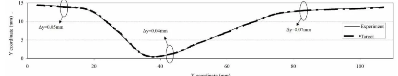
To verify the analytical results, an asymmetric channel forming test is performed on the applied sheet. The obtained die geometry from the analytical approach (Fig. 5) is used to produce the desired die parts by a CAD/CAM machine. The gap between the die components is set to the sheet thickness (1 mm) at the end of loading (Fig. 1). The die components and the final product are shown in Fig. 9. The obtained product is compared with the target geometry in Fig. 10. The normalized RMS error (compared with the target geometry) is evaluated as 3.7%. The shape error for three random points is also shown in this Figure. It can be seen that the shape error is negligible.
VIII. CONCLUSION
The results shown that the presented analytical approach, can predict the springback deformation in channel forming, with high precision and quickly. Also it can be applied for the springback compensation by die modification. This approach yields the optimum die shape in one step calculation and it is not required to perform an iterative algorithm.
The presented inverse algorithm for springback compensation by FEM can be applied for more complicated three dimensional problems. This algorithm is an iterative algorithm and requires considerable time to propose the optimum die shape. The results of the analytical approach and FE analysis coincided for similar cases.
The verification of the analytical results by the experiment is shown that the precision of the obtained results is acceptable for industrial application.
REFERENCES
[1] Z.C. Xia, C.E. Miller and F. Ren, “Experimental and numerical investigation of a split-ring test for springback”, Journal of Manu. Sci. Eng., 2007, 129, pp. 352-359.
[2] YC. Liu, “The effect of the restraining force on shape deviations in flanged channels”, Journal of Engineering Materials and Technology, 1988, 110, pp. 389-394.
[3] M. Sunseri, J. Cao, A. P. Karafillis and M. C. Boyce, “Accommodation of Springback Error in Channel Forming Using Active Binder Force Control: Numerical Simulations and Results”, Journal of Engineering Materials And Technology, 1996, 118(3), pp. 426-35.
[4] A. P. Karafillis and M. C. Boyce, ” Tooling and binder design for sheet metal forming processes compensating springback error”. Int. J. Machine Tools & Manufacturing, 1996, 36, pp. 503-526.
[5] E. L. Anagnostou, “Optimized tooling design algorithm for sheet metal forming over reconfigurable compliant tooling”. NUMIFORM 2004, 712, pp. 741-748.
[6] W. Gan and R.H. Wagoner, “Die design method for sheet springback”. Int. J. Mech. Sci., 2004, 46, pp. 1097-1113.
[7] W. Gan, R.H. Wagoner, K. Mao, S. Price and F. Rasouli, “Practical methods for the design of sheet formed components”. J. Eng. Mat. Tech., 2004, 126, pp. 360-367.
[8] A. Rosochovski, “Die compensation procedure to negate die deflection and component springback”. J. Mat. Proc. Tech., 2001, 115, pp.187-191.
[9] R. Lingbeek, J. Huetink, S. Ohnimus, M. Petzoldt and J. Weiher, “The development of a finit elements based springback compensationtool for sheet metal products”. J. Mat. Proc. Tech., 2005, 169, pp. 115-125. [10] H.S. Cheng, J. Cao and Z.C. Xia, “An accelerated springback
compensation method”. Int. J. Mech. Sci., 2007, 49, pp.267-279. [11] T. Meindres, I.A. Burchitz, M.H.A. Bonte and R.A. Lingbeek,
“Numerical product design: Springback prediction, compensation and optimization”. Int. J. Machine Tools & Manu., 2008, 48, pp.499-514. [12] A. Behrouzi, B. Mollaei and M. Shakeri, “A New Approach for Inverse Analysis of Springback in Sheet Bending Process”. Journal of Engineering Manufacture, 2008, 222, pp.163-1374.
[13] L.J. Vin, A.H. Streppel, U.P. Singh, and H.J.J. Kals, “A process model for air bending”. J. Mat. Proc. Tech, 1996, 57, pp. 48-54.
[14] Z. Dongjuan, C. Zhenshan, R. Xueyu and L.Yuqiang, “An analytical model for predicting springback and side wall curl of sheet after U-bending”. Computation Materials Sci., 2007, 38, pp. 707-715. [15] H. Kim, N. Nargundkar, and T. Altan, “Prediction of bend allowance
and springback in air bending”. ASME- J. Manufacturing Sci. Eng., 2007, 129, pp. 342-351.
[16] D.K. Leu and C.M. Hsieh, “The influence of coining force on spring-back reduction in V-die bending process”. J. Mat. Proc. Tech, 2008, 196, pp. 230-235.
Figure 9. Asymmetric channel forming test.
Figure 8. Convergence diagram of the FE algorithm.