www.adv-radio-sci.net/4/33/2006/ © Author(s) 2006. This work is licensed under a Creative Commons License.
Radio Science
Computation of antenna pattern correlation and MIMO
performance by means of surface current distribution and
spherical wave theory
O. Klemp, G. Armbrecht, and H. Eul
Universit¨at Hannover, Institut f¨ur Hochfrequenztechnik und Funksysteme, Hannover, Germany
Abstract. In order to satisfy the stringent demand for an accurate prediction of MIMO channel capacity and diver-sity performance in wireless communications, more effec-tive and suitable models that account for real antenna radi-ation behavior have to be taken into account. One of the main challenges is the accurate modeling of antenna correla-tion that is directly related to the amount of channel capacity or diversity gain which might be achieved in multi element antenna configurations. Therefore spherical wave theory in electromagnetics is a well known technique to express an-tenna far fields by means of a compact field expansion with a reduced number of unknowns that was recently applied to derive an analytical approach in the computation of antenna pattern correlation. In this paper we present a novel and ef-ficient computational technique to determine antenna pattern correlation based on the evaluation of the surface current dis-tribution by means of a spherical mode expansion.
1 Introduction
In this article the analysis of the input multiple-output (MIMO) transmission behavior of antenna modules will be evaluated based upon an expansion of antenna surface current distribution represented by a series expansion involv-ing spherical eigenmodes as in Stratton (1941) and Werner and Mittra (2000). The latter mathematical description yields a representation of antenna radiation patterns with a reduced order and therefore provides the advantage of an analytical approach in the description of multielement antenna trans-mission parameters. Therefore we present a modified tech-nique of spherical mode expansion as in Chen et al. (1992) based upon a computation of vector expansion coefficients of the field approach that were directly derived by the surface-current distribution on the antenna elements taken into con-Correspondence to:O. Klemp ([email protected])
sideration. Based upon a suitable statistical model to in-clude for the spatial properties of a multipath propagation scenario as given in Jakes (1974), a closed form represen-tation for antenna correlation may be derived as shown in Leifer (2002) and Klemp and Eul (2005). This representation of antenna correlation may be directly related to the compu-tation of MIMO channel capacity as for the description of MIMO communication systems employing a certain number of antenna elements at the transmitter and at the receiver.
b) trapezoid antenna, M=5 r
o
r
o
arm 4 arm 3
arm 2
arm 1 y
x
arm 4 arm 3
arm 2
arm 1 y
x
a) trapezoid antenna, M=1
Fig. 1. Trapezoidal four-arm antenna elements with M=1 and
M=5 periods of the trapezoidal unit cell.
or MIMO capacity. Based on the field expansion in terms of spherical eigenmodes, an investigation of the modal contri-butions to the overall antenna correlation can be performed additionally. In particular the analysis can be used to predict the MIMO performance of antenna elements in distinct chan-nel scenarios by simply specifying their spectra of spherical eigenmodes.
The article is organized as follows, Sect. 2 summarizes the properties of self-complementary, four-arm, log.-per. planar antennas for applications with dual polarization. In Sect. 2.1 we review the fundamental properties of the spherical mode expansion technique with respect to the electric- and mag-netic vector potential of a given elementary source distri-bution and apply this approach to the surface current dis-tribution of the antenna elements taken into consideration. Section 3 is used to introduce the basic principles of MIMO transmission involving a channel structure based on the Kro-necker model. Computing the modal representation of an-tenna radiation patterns as in Sect. 3.1 we derive an analytical approach for antenna power correlation based on the surface currents on the interactive antenna elements. The presented analysis is adopted to the computation of MIMO channel ca-pacity in Sect. 4 for dual-polarized log.-per. planar four-arm antennas on each side of the communication link. Section 5 concludes this article.
2 Antennas for broadband polarization diverse transmission
Logarithmically-periodic antenna elements may theoreti-cally provide frequency independent transmission character-istics (DuHamel and Isbell, 1957; Rumsey, 1957) if they ad-here to the principle of self-complement. Designed as a pla-nar logarithmically-periodic four-arm antenna element it of-fers dual linear polarization as shown in e.g. Klemp et al. (2005). Dual linear operation results from the odd-phase ex-citation of each of the two pairs of adjacent antenna arms. Antenna elements of that kind can be applied in a broadband antenna system for MIMO operations using dual orthogo-nal polarizations. In comparison to antenna configurations
exploiting spatial diversity concepts, polarization diverse air interfaces provide independent branches for signal reception with a much smaller spatial extent.
In this paper, the planar, log.-per. four-arm trapezoid an-tenna as in Klemp et al. (2004) is used in order to demon-strate its capabilities as a compact polarization-diverse an-tenna element for MIMO communications based on an eigen-mode characterization of its surface current distribution. Two different geometrical types of the trapezoid antenna will be investigated according to Fig. 1. Referring to Klemp et al. (2005) the trapezoid antennas taken into consideration are given by M=1 andM=5 periods of the trapezoidal unit cell that provides a trapezoidal slew rate of 50%.
The outer radii of the antenna elements amount to ro=50 mm and the antenna radiation behavior will be
eval-uated in free-space.
In order to derive a compact representation of antenna ra-diation behavior, the field quantities can be expanded by a compact set of spherical eigenmodes whose weights are com-puted from the appropriate current distribution on the an-tenna surface (e.g. Chen et al. (1992)). This field expansion yields a distinct set of vector expansion coefficients that is solely dependent on the excitation and the geometrical shape of the antennas taken into consideration. Therefore the spher-ical mode expansion may yield a significant order reduction in the description of antenna radiation behavior that speeds up computations of field-related quantities as e.g. the compu-tation of antenna correlation and MIMO channel capacities. In Sect. 2.1 the results of the field expansion based on the surface current distribution are summarized.
2.1 Spherical mode spectra of log.-per. antenna elements Following the procedure of spherical mode expansion for planar, log.-per. antenna elements based on its surface cur-rent distribution as given by Armbrecht et al. (2006), this sec-tion summarizes the spectra of spherical eigenmodes for the log.-per. trapezoid antennas withM=1 andM=5 periods of the trapezoidal unit cell as shown in Fig. 1.
As an example, Fig. 2 shows the normalized SME coeffi-cients at a simulation frequency of 3 GHz. The normaliza-tion is performed with respect to the absolute value of the expansion coefficient of degreem=0 and ordern=0,a00, which yields normalized weightsanm
/
a00
in terms of
expansion coefficients related to even spherical harmonics Ynme (ϑ, ϕ)andbnm/
a00for expansion coefficients of
1 3 5 7 9 11 13 15 17 19 21 23 25 27 29 31 10
-3
10
-2
10
-1
10
0
modal index
n
o
r
m
a
l
i
z
e
d
|
|
a
n
,m
|
|
,
|
|
b
n
,m
|
|
M = 1 @ 6.0 GHz
M = 5 @ 6.0 GHz
Fig. 2. Normalized coefficients of the spherical mode expansion for trapezoid antennasM=1 andM=5 at 3 GHz. See Armbrecht et al. (2006) for the appropriate enumeration of the abscissa.
3 Multiple-input multiple-output antenna systems
Multiple-input multiple-output antenna systems may effi-ciently exploit the spatial domain by parallel subchanneling employing decoupled transmit- and receive paths as shown in Foschini (1996), Yu and Ottersten (2002). Due to the ability of transmitting simultaneous data streams incorporat-ing antenna arrays at both sides of the radio link, a great increase of channel capacities in wireless communications may be achieved. The establishment of parallel subchannels is a result of uncorrelated fading processes between individ-ual transmission paths of the communication link and can be a result of spatial-, pattern- or polarization diverse prop-erties of the applied antenna elements. Depending on the properties of the regarded multipath channel, the application of dual-polarized antenna modules at the receiver and at the transmitter is possible. Compared to MIMO techniques ex-ploiting spatial diversity concepts, using polarization-diverse air interfaces leads to the design of compact transmission ter-minals with enhanced transmission capacity.
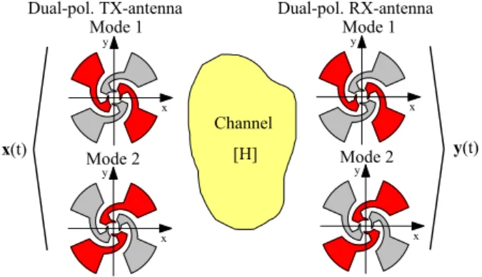
Figure 3 shows the model of the considered wireless MIMO system incorporating log.-per. antenna elements on both sides of the radio link. The four-arm antenna structures provide orthogonal-polarized operational modes by feeding one of the two adjacent antenna arm pairs with an odd phase relation. Using one antenna element with dual linear polar-ization at the transmit (TX) side and one antenna element with dual linear polarization at the receive (RX) side yields a (2×2)-MIMO communication system.
Given frequency flat signal vectors of the TX- and the RX antenna array, x andy, the channel matrix equation of the corresponding frequency flat channel following Yu and Ot-tersten (2002) is given as follows:
y=H x+n. (1)
y
x y
x
Dual-pol. RX-antenna Dual-pol. TX-antenna
y(t) x(t)
Channel
[H] Mode 1
Mode 2 Mode 2
Mode 1
y
x
y
x
Fig. 3.Model of the MIMO radio channel incorporatingnTX anten-nas at the TX-side andnRXantennas at the RX-side.
His the narrowband transmission matrix of the MIMO chan-nel andndescribes zero-mean additive white Gaussian noise with a variance of σn2. The complex correlation coeffi-cient between independent operational modesiandj at the transmitter- or at the receiver side is given in accordance with Taga (1990) for incident phase centers as:
ρiTX,j ,RX=
RiTX,j ,RX
q
σiTX,RX2σjTX,RX2
. (2)
From Eq. (2) antenna correlationρiTX,j ,RXdepends on antenna covarianceRTXi,j ,RXand the variancesσiTX,RX2 andσjTX,RX2. Ri,jcan be computed from the radiation patternsC(ϑ, ϕ)of
operational modeiand operational modej, as follows:
Ri,j =K
Z 2π
0
Z π
0
h
Cϑ,i(ϑ, ϕ) Cϑ,∗j(ϑ, ϕ) (3) + XPDCϕ,i(ϑ, ϕ) Cϕ,∗j(ϑ, ϕ)
i
pϑ,ϕ(ϑ, ϕ)sinϑ dϑ dϕ .
In Eq. (3),pϑ,ϕ(ϑ, ϕ)denotes a two-dimensional
probabil-ity densprobabil-ity function that accounts for the spatial property of outgoing waves at the transmitter and impinging waves at the receiver. The ratio of the mean incident power in vertical di-rection to the mean incident power in horizontal didi-rection at the locations of receiver and transmitter is given by the cross-polarization discrimination XPD. ’∗’ means conjugate oper-ation andKis a proportionality constant. Replacingi=j in Eq. (3) yields the variances of the operational modesiandj, σiTX,RX2,σjTX,RX2, respectively.
The correlation values between any possible combination of adjacent port-related antenna patterns at the TX- and at the RX-side will be combined to correlation matrices RTX
ofH. Initially, the elements ofHare assumed to be uncorre-lated zero-mean complex Gaussian variables with a unit vari-ance. The appropriate correlation values between the channel coefficients are computed from matrix multiplication with the correlation matrixRTX⊗RRXas shown in Kermoal et al. (2002).
Provided a uniform power allocation between the in-dependent operational modes at the transmit antenna, the ergodic MIMO channel capacity s given as a sum over Ksubchannels:
C=
K
X
k=1
log2
1+λk
Pk
σ2
n
. (4)
In Eq. (4),Pk denotes the amount of power assigned to the
kth subchannel andσn2is the total noise power at the receiver. λkgives the eigenvalue of thek-th subchannel.
3.1 SME-based computation of antenna pattern correlation In order to simplify the computation of antenna pattern corre-lation and MIMO channel capacity which are directly related to the radiation patterns of the involved antenna elements as shown in Sect. 3, a spherical mode expansion of the surface current distribution will be accomplished. Due to the fact, that the radiation patterns of each antenna element may be described by a distinct set of modal expansion coefficients this analysis is predestined to provide a deeper insight into the radiation mechanisms that cause high values of pattern correlation and low channel capacities. Furthermore it will become possible to optimize delimiting antenna geometries with respect to certain cost functions of related transmission parameters that take into account the real antenna radiation behavior.
As shown in Armbrecht et al. (2006), antenna radiation patternsC(ϑ, ϕ)of an arbitrary antenna geometry can be ex-pressed by an expansion of the current distribution on the re-spective antenna geometry by means of an orthogonal set of spherical basis functions as shown in Eq. (5). The subsequent analysis is based on planar antenna geometries, whose met-alization surfaces are located in parallel to thexy-plane of a cartesian coordinate system. Surface current distributions
J x′, y′
=Jx x′, y′, Jy x′, y′(wherex′andy′
indi-cate the cartesian coordinates of the source region) are de-rived using a conventional full-wave simulator based on the finite-element-method (FEM). Assuming far-field conditions of the electromagnetic field, the spherical mode expansion of the surface current distribution yields:
Cϑ,i
Cϕ,i
= −j kη ∞
X
n=0
n
X
m=0
jn
cosϑcosϕcosϑsinϕ −sinϕ cosϕ
"
ax,inimi b
x,i
nimi
ay,inimi b
y,i
nimi
#
Yne
imi(ϑ, ϕ) Yno
imi(ϑ, ϕ)
. (5)
In Eq. (5), spherical harmonicsYnme (ϑ, ϕ) andYnme (ϑ, ϕ) are mapped to the spherical componentsCϑ,i, Cϕ,i of
an-tenna radiation patterniincorporating a field expansion ma-trix including vector expansion coefficientsain
imi,b
i
nimi as
derived from the surface current distribution of operational modeiand an additional matrix that accounts for coordinate transformation. The coordinate transform of the cartesian components of the surface currentsJx x′, y′andJy x′, y′
into spherical components is mandatory in order to apply the Fraunhofer approximation of the electromagnetic field (Lo and Lee, 1988). For convenience, in Eq. (5), the upper in-finite summation index of the spherical eigenfield decompo-sition has to be replaced by a finite valueN leading to im-pairments in the synthesized far-field representation. Those impairments can be reduced by adhering to the convergence criteria for spherical wave expansions as in Narasimhan et al. (1985). Therefore a sufficient degree of field approximation is derived forN≥ka,adenoting the radius of a sphere that is completely enclosing the considered antenna andk is the scalar wave number.
Splitting the integral for covariance computationRi,j as
given in Eq. (3) into two parts,Ri,jϑ andRϕi,j that account for the contributions of antenna covariance in the directions ofϑ andϕand replacingC(ϑ, ϕ)by the eigenfield decomposition as given in Eq. (5), it follows:
Ri,jϑ,ϕ=K ∞
X
ni=0
ni
X
mi=0
∞
X
nj=0
nj
X
mj=0
jnijn∗j
Tee Iee,M ϑ,ϕ 1
nimi,njmj
Iee,M ϑ,ϕ 2
nimi,njmj
Iee,M ϑ,ϕ 3
nimi,njmj
+Teo
Ieo,M ϑ,ϕ 1
nimi,njmj
Ieo,M ϑ,ϕ 2
nimi,njmj
Ieo,M ϑ,ϕ 3
nimi,njmj
+Toe
Ioe,M ϑ,ϕ 1
nimi,njmj
Ioe,M ϑ,ϕ 2
nimi,njmj
Ioe,M ϑ,ϕ 3
nimi,njmj
+Too
Ioo,M ϑ,ϕ 1
nimi,njmj
Ioo,M ϑ,ϕ 2
nimi,njmj
Ioo,M ϑ,ϕ 3
nimi,njmj
. (6)
In Eq. (6), Ie,oe,o,M ϑ ξ
nνmν,nµmµ (with ν=i, j, µ=i, j and ξ=1, . . . ,3) denote coupling integrals between two spher-ical harmonics Yne,ojmj(ϑ, ϕ) in a distinct channel scenario pϑ,ϕ(ϑ, ϕ), weighed by a field-point dependent factor
Mξϑ(ϑ, ϕ)as follows:
Ie,oe,o,M ϑ ξ
nνmν,nµmµ
Ie,oe,o,M
ϕ ξ
nνmν,nµmµ
=
Z 2π
ϕ=0
Z π
ϑ=0
Mϑ ξ (ϑ, ϕ)
Mξϕ(ϑ, ϕ)
(7)
Yne,o
imi(ϑ, ϕ) Y
e,o
njmj(ϑ, ϕ) pϑ,ϕ(ϑ, ϕ)sinϑ dϑ dϕ . The antenna-dependent scaling factorsTee,Teo,ToeandToo
in Eq. (6) are given entirely with respect to the field expan-sion coefficients:
Tee=
ax,in imia
x,j∗
njmj
axn imia
y∗
njmj +a
y,i
nimia
x,j∗
njmj
ay,inimia
y,j∗
njmj
Teo=
ax,in imib
x,j∗
njmj
axn imib
y∗
njmj+b
y,i
nimia
x,j∗
njmj
ay,inimia
y,j∗
njmj
, (9)
Toe=
bx,in imia
x,j∗
njmj
bxn imia
y∗
njmj+b
y,i
nimia
x,j∗
njmj
by,inimia
y,j∗
njmj
(10)
and
Too=
bx,in imib
x,j∗
njmj
bxn imib
y∗
njmj +b
y,i
nimib
x,j∗
njmj
by,inimib
y,j∗
njmj
. (11)
The field-point dependent factorsMξϑ(ϑ, ϕ)related to the ϑ-component of the antenna radiation pattern can be computed from:
M1ϑ(ϑ, ϕ) M2ϑ(ϑ, ϕ) M3ϑ(ϑ, ϕ)
=
cos2ϑcos2ϕ) cos2ϑcosϕsinϕ
cos2ϑsin2ϕ
. (12)
The scaling factors Mξϕ(ϑ, ϕ) that are related to the ϕ-component ofC(ϑ, ϕ)yield:
M1ϕ(ϑ, ϕ) M2ϕ(ϑ, ϕ) M3ϕ(ϑ, ϕ)
=
sin2ϕ −cosϕsinϕ
cos2ϕ
. (13)
As can be seen from Eq. (6), a complete separation between antenna- and channel dependent quantities is achieved. It is also an important advantage that the values of the coupling integrals in Eq. (7) remain fixed within a distinct channel sce-nariopϑ,ϕ(ϑ, ϕ). Due to the fact that antenna radiation
be-havior is characterized in terms of an SME by its vector field expansion coefficientsain
imi andb
i
nimi, the effect of chang-ing the antenna topology or geometry of schang-ingle antenna ele-ments within the considered channel scenario can be easily obtained from Eq. (6).
3.2 Correlation properties of log.-per. four-arm antennas
In this section the correlation properties of log.-per. an-tenna elements at the transmitter or at the receiver are in-vestigated. The analysis is accomplished using the novel ap-proach for the computation of power correlation as derived in Sect. 3.1 based on the SME expansion of the surface current distributions of the related antenna elements. Results were computed in terms of a two-dimensional probability density pϑ,ϕ(ϑ, ϕ) applying a Laplacian dependence in azimuth ϕ
and a Gaussian dependence in elevationϑin accordance to Taga (1990) featuring mean valuesmϕ=90◦,mϑ=90◦and
angular spreadsσϕ=10◦,σϑ=10◦.
Antenna power correlation is computed between the vec-tor antenna radiation patternsCi,j(ϑ, ϕ)related to the opera-tional modesiandj of the antenna element with dual linear
1 2 3 4 5 6
0.00 0.05 0.10 0.15 0.20 0.25 0.30
p
o
w
e
r
c
o
r
r
e
l
a
t
i
o
n
P
frequency in GHz conventional FEM
SME, N = 3
SME, N = 4
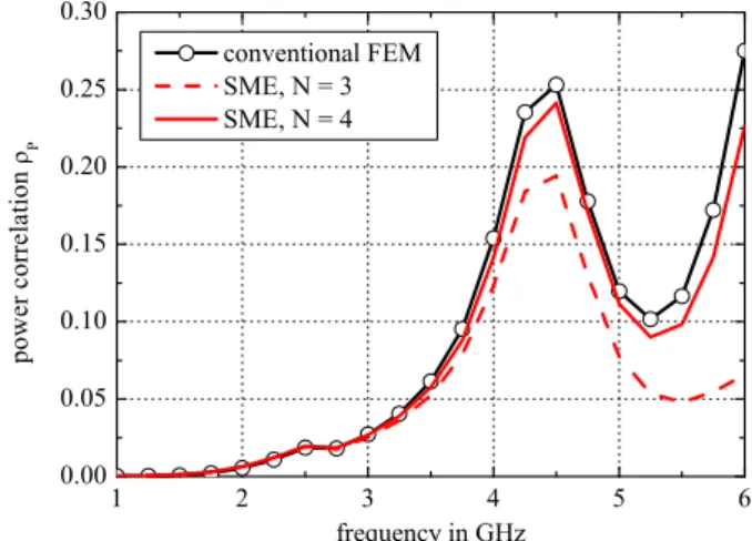
Fig. 4. Power correlation between orthogonal operational modes for trapezoid antennaM=1.
polarization. Figure 4 shows the results for antenna power correlationρP evaluated by the standard approach involving
electric far-fields derived by methods of FEM (see Eq. (3)) and a spherical mode expansion of the surface-current dis-tribution. Results are shown in the predestined frequency range of the antenna elements between 1 GHz and 6 GHz. Increasing the order of the field approach ameliorates the fit between the two computational approaches (FEM and SME) as can be seen from Fig. 4. Therefore including a maximum orderN=4 seems adequate for the trapezoid antennaM=1 that is depicted in Fig. 1a. Due to the imperfect polarization decoupling between the two operational modes of this an-tenna element,ρP yields a peak at the frequency of 4.3 GHz
and a local maximum at the upper frequency of 6 GHz of the considered frequency range. According to the trapezoid an-tenna includingM=5 periods of the trapezoidal unit cell as depicted in Fig. 1b, the results of power correlationρP are
shown in Fig. 5. Due to excellent polarization decoupling between the two pairs of adjacent antenna arms for this an-tenna element, power correlation remains below 0.015 in the entire frequency range. Despite those low numerical values forρP the results derived by spherical eigenfield
decomposi-tion of the surface current distribudecomposi-tion including a maximum expansion degreeN=3 are in an excellent agreement.
4 Analysis of MIMO antenna performance by means of SME
1 2 3 4 5 6 0.00
2.50x10
-3
5.00x10
-3
7.50x10
-3
1.00x10
-2
1.25x10
-2
p
o
w
e
r
c
o
r
r
e
l
a
t
i
o
n
P
frequency in GHz conventional FEM
SME, N = 3
Fig. 5. Power correlation between orthogonal operational modes for trapezoid antennaM=5.
in comparison to the conventional, FEM-based results. The results in this section are limited to a maximum degree of N=3 for the spherical wave expansion.
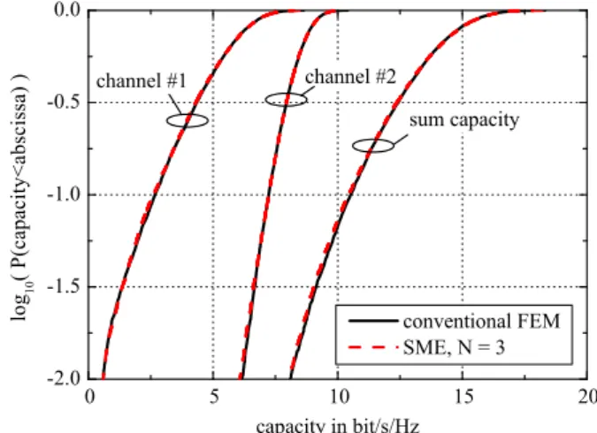
Figures 6 and 7 show the results for MIMO channel ca-pacity in terms of cumulative distribution functions (CDFs) of the outage capacity in bit/s/Hz for the trapezoid an-tenna M=1. At 3 GHz, the results of conventional FEM-based computation and spherical mode expansion are in a very good agreement, as can be seen from Fig. 6. Re-garding the sum capacity for the (2×2)-MIMO transmis-sion link, both computational techniques consistently yield a 10%-outage capacity of 10.45 bit/s/Hz. At a simulation frequency of 6 GHz, where slight deviations between the two computational techniques were reported in terms of an-tenna power correlation ρP (see Fig. 4), the results for
con-ventional computed channel capacity and channel capacity as derived by means of SME (N=3) are not in an excel-lent agreement. Following the values for the 10%-outages of the channel capacity, spherical mode expansion exhibits a slight overestimation of the channel capacity resulting in C10%,6GHz=10.4 bit/s/Hz. Conventional, FEM-based
com-putations yield a value of 10.2 bit/s/Hz. Especially the CDF for the weaker channel of the transmission link can not be approximated very well by means of SME. This result is due to the small contributions of this spatial subchannel to the overall capacity of the MIMO link, where impairments in the field-representations due to an inadequate degree of modal field expansion become visible first.
This result is in a close agreement to the values for an-tenna power correlation at 6 GHz as shown in Fig. 4. In this case, SME yields a power correlation of 0.07 whereas con-ventional, FEM-based computations lead toρP =0.28. As
can be seen from these results, frequency variation of the er-godic channel capacity is extremely low.
The results for using trapezoid antennas withM=5 pe-riods of the trapezoidal unit cell (see Fig. 1b) in a(2× 2)-MIMO communication link are depicted in Fig. 8 at 3 GHz
0 5 10 15 20
-2.0 -1.5 -1.0 -0.5 0.0
channel #1 channel #2
l
o
g
1
0
(
P
(
c
a
p
a
c
i
t
y
<
a
b
s
c
i
s
s
a
)
)
capacity in bit/s/Hz
conventional FEM
SME, N = 3 sum capacity
Fig. 6.CDF of MIMO channel capacity forM=1 antenna at 3 GHz derived from FEM computations and SME,N=3.
0 5 10 15 20
-2.0 -1.5 -1.0 -0.5 0.0
channel #1
channel #2
l
o
g
1
0
(
P
(
c
a
p
a
c
i
t
y
<
a
b
s
c
i
s
s
a
)
)
capacity in bit/s/Hz
conventional FEM
SME, N = 3 sum capacity
Fig. 7.CDF of MIMO channel capacity forM=1 antenna at 6 GHz derived from FEM computations and SME,N=3.
0 5 10 15 20 -2.0
-1.5 -1.0 -0.5 0.0
channel #1 channel #2
l
o
g
1
0
(
P
(
c
a
p
a
c
i
t
y
<
a
b
s
c
i
s
s
a
)
)
capacity in bit/s/Hz
conventional FEM
SME, N = 3 sum capacity
Fig. 8.CDF of MIMO channel capacity forM=5 antenna at 3 GHz derived from FEM computations and SME,N=3.
5 Conclusions
This paper presented a generalized approach for the com-putation of antenna power correlation and MIMO channel capacity in multielement antenna arrangements based on a spherical mode expansion of the respective surface current distributions. The analysis was applied in order to charac-terize the power correlation and channel capacity for pla-nar, dual-polarized log.-per. four-arm antenna elements. The characterization of the MIMO radio channel was based on a simple stochastic model that accounted for the spatio-temporal behavior of signal fading at the transmitter and at the receiver. Results based on the introduced spherical mode expansion were found to be in a very close agreement to the results as derived by conventional FEM-based computations. The major advantages of this work is the complete analytical description of the link-related transmission parameters like antenna power correlation and channel capacity by means of spherical harmonics. Due to the fact that the coefficients of field expansion that are directly related to the surface cur-rent distribution on the related antenna elements are sepa-rated mathematically from the quantities that characterize the channel model, this approach allows a clearer insight into the field-related properties of MIMO communications systems. It may be additionally used in order to optimize or fit certain antenna geometries to distinct channel scenarios.
References
Armbrecht, G., Klemp, O., and Eul, H.: Spherical Mode Analysis of Planar Frequency-Independent Multi-Arm Antennas Based on Its Surface Current Distribution, Accepepted for publ. in Adv. Radio Sci., 2006.
Chen, Y., Simpson, T. L., and Ho, T. Q.: Highly efficient technique for solving radiation and scattering problems, IEE Proc.-H, 139, 7–10, 1992.
0 5 10 15 20
-2.0 -1.5 -1.0 -0.5 0.0
channel #1 channel #2
l
o
g
1
0
(
P
(
c
a
p
a
c
i
t
y
<
a
b
s
c
i
s
s
a
)
)
capacity in bit/s/Hz
conventional FEM
SME, N = 3 sum capacity
Fig. 9.CDF of MIMO channel capacity forM=5 antenna at 6 GHz derived from FEM computations and SME,N=3.
DuHamel, R. H. and Isbell, D. E.: Broadband Logarithmically Pe-riodic Antenna Structures, IRE Intern. Conv. Rec., 5, 119–128, 1957.
Foschini, G. J.: Layered space-time architecture for wireless com-munication in fading environment when using multiple antennas, Bell Labs Tech. J., 41–59, 1996.
Jakes, W. C.: Microwave Mobile Communications, IEEE Press, Inc., New York, 1974.
Kermoal, J. P., Schumacher, L., Pedersen, K. I., Morgensen, P. E., and Frederiksen, F.: A Stochastic MIMO Radio Channel Model With Experimental Validation, 20, 1211–1226, 2002.
Klemp, O. and Eul, H.: Radiation Pattern Analysis of Antenna Sys-tems for MIMO and Diversity Configurations, Adv. Radio Sci., 3, 157–165, 2005.
Klemp, O., Schultz, M., and Eul, H.: A Planar Broadband Antenna for Applications in WLAN and 3G, Proc. of the 2004 Intern. Sympos. Signals, Systems and Electronics ISSSE, Austria, 2004. Klemp, O., Schultz, M., and Eul, H.: Novel Logarithmically Pe-riodic Antenna Structures for Broadband Polarization Diversity Reception, AEUE, Intern. J. on Electronics and Commun., 59, 268–277, 2005.
Leifer, M. C.: Signal Correlations in Coupled Cell and MIMO antennas, Antennas and Propagation Soc. Intern. Symp., 16-22 June 2002, 3, 194–197, 2002.
Lo, Y. T. and Lee, S. W.: Antenna Handbook - Theory, Applications and Design, Van Nostrand Reinhold Company, New York, 1988. Narasimhan, M. S., Christopher, S., and Varadarangan, K.: Modal Behavior of Spherical Waves from a Source of EM Radiation with Application to Spherical Scanning, 33, 350–354, 1985. Rumsey, V. H.: Frequency Independent Antennas, IRE Intern.
Conv. Rec., 5, 114–118, 1957.
Stratton, J. A.: Electromagnetic Theory, McGraw Hill, New York, 1941.
Taga, T.: Analysis for Mean Effective Gain of Mobile Antennas in Land Mobile Radio Environments, 39, 117–131, 1990.