Faculty of Engineering of the University of Porto
Contributions for a simulation framework for
designing and evaluation manufacturing systems
Tiago André da Silva Leite Constante
This Dissertation was developed for the
Integrated Master in Electrical and Computer Engineering
Major: Automation
Supervisor: Prof. Doctor Américo Azevedo
Co-supervisor: Prof. Doctor Samuel de Oliveira Moniz
ii
iii
Abstract
In an Industry 4.0 environment, where the concept is widely-spread around the globe and within several businesses, the generation of a huge amount of information creates the need to deal with this information to extract meaningful knowledge about how a system behaves and, the relationship between different elements in manufacturing, thus creating an excellent opportunity to simulate the manufacturing system aiming to predict its behavior through different scenarios, or analyze the post-simulation data and take measures to ensure the viability, stability or even profitably of the manufacturing system.
The current simulation software market already offers some programs with tremendous capabilities to design and evaluate manufacturing systems, like SIMIO or Anylogic, but like any other program they have their pros and cons, thus creating an opportunity to create a new simulation framework, to design and evaluate these same manufacturing systems, while trying to improve the flaws or overcoming the lack of features of the existing simulation options in the market. These same simulation tools still have a low performance regarding the decision-making process in real time.
Therefore, this dissertation has the objective of designing, developing and presenting a new simulator, based on concepts from the current simulators, and taking their examples to improve in some respects to make the simulation easier, while trying to create a digital twin of the manufacturing system and allow the automation of processes, like the development of complex metaheuristics.
The resulting simulator framework is still in an early stage of development. It has an excel interface to input data, that, when filled with the needed information, the simulator will easily process the information and create a manufacturing system automatically with all the main simulation blocks needed to simulate it. When benchmarked with SIMIO, the simulator that has been developed still lacks many relevant features and other developments, but at the same time it offers some advantages comparing to SIMIO. Plus, since this new simulator uses Java and Excel files only, it can run not only in Windows but also in Mac and Linux operating systems.
v
Acknowledgments
When tight deadlines are in front of me my main focus is attack as soon as possible the problem to prevent unexpected delays. This semester was not a particularly good semester in terms of health but with the support and patience I found within the INESC TEC it made my journey smoother and ultimately easier, this special gratitude goes to my dear friend and colleague Ruben Dias and the investigator Luís Lima that never failed me when I needed them.
Throughout my journey in this faculty, I was not only a student but also a member of the staff of my department, so some thanks must be addressed to all people who doesn’t teach in a classroom but teach everything they could and tried to keep me focus on studies, this thanks is for both Professor Doctors Pedro Guedes de Oliveira and Adriano da Silva Carvalho, as well to Isidro Ribeiro Pereira, Maria do Rosário Macedo and my colleague Nuno Guerra, which had the patience and support inexhaustible.
From the moment I became Gonçalo Falcão’s friend we became almost inseparable, the same happened to my beloved friend Filipe Barros and lastly to my dear friend André Leite, which without these three friends I wouldn’t make here.
Lastly, I have to thank and give my hearth to four persons that tried to always be there for me, my mother, Emília Leite, who always tried to make the best she could and to Lurdes and Silvino Araújo, as well as their daughter Cristina, who aren’t my blood relatives, but provided me all the tools I needed to finish this journey, who teach me to focus, to love, to forgive and always shown a tremendous amount of generosity and love.
vii
Index
Abstract ... iii
Acknowledgments ... v
Index ... vii
Figures list ... ix
Tables list ... xi
Abbreviations and Symbols ... xiii
Abbreviations list ... xiii
Chapter 1 ... 1
Introduction ... 1
1.1 - Context ... 1
1.2 - Motivation and Objectives ... 2
1.3 - Contribution Highlights ... 3
1.3.1 - Impact of the thesis and work developed ... 3
1.3.2 - Methodology ... 3
1.3.3 - Thesis sections summary ... 4
Chapter 2 ... 5
Literature Review ... 5
2.1 - Industry 4.0 – Cyber-physical System (CPS) ... 5
2.1.1 - Key paradigms of Industry 4.0 ... 6
2.1.2 - Industry 4.0 and technologies ... 7
2.1.3 - Simulation in Industry 4.0 ... 7
2.2 - Digital twin in manufacturing ... 8
2.2.1 - Applications of Digital Twin ... 9
2.3 - Simulation modelling ... 11
2.3.1 - Agent-Based Simulation ... 12
2.3.2 - System Dynamics ... 13
2.3.3 - Discrete Event Simulation ... 14
Chapter 3 ... 15
Simulation Modeling Design ... 15
3.1 - Definition of the problem ... 15
3.1.1 - Challenges and approaches ... 15
viii
3.1.3 - Initial concept ... 16
3.2 - Solution Review ... 17
3.2.1 - Object-oriented programming language ... 17
3.2.2 - Graphical User Interface ... 18
3.2.3 - Input/output data stream ... 19
3.2.4 - Final concept ... 19
3.3 - Proposed Solution ... 20
3.3.1 - Simulator block... 20
3.3.2 - Input Data block ... 25
3.3.3 - GUI block ... 29
3.3.4 - Output Data block ... 32
Chapter 4 ... 33
Simulation Model Assessment ... 33
4.1 - Case study... 33
4.1.1 - Proposed case study ... 33
4.1.2 - Results from the simulator framework ... 37
4.1.3 - Discussion and argumentation ... 38
4.2 - Benchmarking ... 39
4.2.1 - Case study results... 39
4.2.2 - SIMIO versus the developed simulation framework ... 41
Chapter 5 ... 45
Conclusion... 45
5.1 - Dissertation’ assessment ... 45
5.2 - Future work ... 46
ix
Figures list
Figure 2.1 Digital Twin in manufacturing ... 8
Figure 2.2 - Digital Twin Product Design ... 9
Figure 2.3 - Number of published papers by simulation technique used ... 11
Figure 2.4 - Generic Scheme of a multi-agent system ... 12
Figure 3.1 - Simulation framework’ initial concept ... 16
Figure 3.2 - Languages development/performance ... 17
Figure 3.3 - AWT/Swing/JavaFX example ... 18
Figure 3.4 - Simulator framework’ final concept ... 19
Figure 3.5 – Event’s Timeline example ... 20
Figure 3.6 - Distribution of the Basic Model Components ... 22
Figure 3.7 - Model example to explain a FIFO dispatching rule ... 24
Figure 3.8 - Unified Modeling Language(UML) of the Input Data block ... 25
Figure 3.9 - Layout example ... 28
Figure 3.10 - Basic layout types ... 30
Figure 3.11 - GUI layout example ... 31
Figure 3.12 - Buffer occupation from day 0 to day 24 ... 32
Figure 4.1 – Diagram of layout and routes ... 33
Figure 4.2 – Mean occupation – in number of entities ... 37
Figure 4.3 - Maximum Occupation - in number of entities ... 37
Figure 4.4 - WIP - in number of entities ... 38
Figure 4.5 - Worst/best case scenarios - in number of entities ... 38
x
Figure 4.7 - Maximum occupation - in number of entities – SIMIO ... 40
Figure 4.8 - WIP - in number of entities – SIMIO... 40
Figure 4.9 - Worst/best scenario - SIMIO ... 41
Figure 4.10 - Event timeline - example 1 – SIMIO ... 42
Figure 4.11 - Event timeline - example 1 - developed simulator ... 42
Figure 4.12 - Event timeline - example 2 – SIMIO ... 42
Figure 4.13 - Event timeline - example 2 - developed simulator ... 43
Figure 4.14 - Event timeline - example 3 – SIMIO ... 43
xi
Tables list
Table 3.1 - ProductMix example ... 23
Table 3.2 - Programing Options example ... 26
Table 3.3 - Product Mix example... 26
Table 3.4 - Source example ... 27
Table 3.5 - Workstations example ... 27
Table 3.6 - Buffers example ... 27
Table 3.7 - Conveyor example ... 27
Table 3.8 - Changeover matrix example ... 28
Table 3.9 - Route example ... 29
Table 4.1 - Case study' product mix ... 33
Table 4.2 - Dimensions of detail for the case study ... 34
Table 4.3 - Average setup and processing times ... 34
Table 4.4 - Changeover matrix for WS1 ... 35
Table 4.5 - Changeover matrix for WS2 ... 35
Table 4.6 - Changeover matrix for WS3 ... 35
Table 4.7 - Changeover matrix for WS4 ... 35
Table 4.8 - Changeover matrix for WS5 ... 35
Table 4.9 - Changeover matrix for WS6 ... 35
Table 4.10 - Changeover matrix for WS7 ... 35
Table 4.11 - Changeover matrix for WS8 ... 35
Table 4.12 - Processing times (in sec.) ... 36
xii
Table 4.14 - Framework results in number of entities ... 37
Table 4.15 - Worst/best case scenarios - in number of entities ... 38
Table 4.16 - Framework results in number of entities -SIMIO ... 39
xiii
Abbreviations and Symbols
Abbreviations list
AGV Automated Guided Vehicles API Application Program Interface avg. Average
AWT Abstract Windows Toolkit
CPPS Cyber-Physical Production System CPS Cyber-physical system
DEEC Departamento de Engenharia Eletrotécnica e de Computadores
DES Discrete Event Simulator
FEUP Faculdade de Engenharia da Universidade do Porto
FIFO First-In-First-Out
GUI Graphical User Interface h. Hours
H High
ICT Information and Communication Technologies
INESC TEC Instituto de Engenharia de Sistemas e Computadores Tecnologia e Ciência IoT Internet of Things
IT Information Technologies
L Low
MHS Material Handling System Min. Minutes
MRO Maintenance, Repair and Overhaul m/s Meters/Second
OS Operating System sec. Seconds
xiv
UML Unified Modeling Language WIP Work-In-Progress
Chapter 1
Introduction
1.1 - Context
With the start and growth of Industry 4.0, referring to the 4th industrial revolution[1] and considering all the terminologies and concepts associated with this revolution it was created a new necessity on those who want to know how their manufacturing production will change with a new route, a new machine associated to an existing route, check costs and profits associated with those changes. This necessity, right now, is being satisfied with some simulation solutions, within this, we have the Discrete Event Simulators (DES).
Right now, and with the growth of the present industries, including the (semi-)autonomous factories, it’s even more necessary to predict the behavior, time consumptions, bottlenecks, costs, profits and so on, of one or multiple routes of a manufacturing system. With the present globalization, manufacturers are under constant pressure not only to cut costs but at the same time, improve delivery speed, product quality, flexibility and delivery reliability at the same time[2]. With this idea in mind, DES started to make their way into an everyday tool to recreate or simulate an enormous number of scenarios, as said above, some of those scenarios include new routes or machinery in the manufacturing process.
With this various scenarios and specifications there is a new necessity, to create a new DES or adapt some libraries to the same purpose, so we can achieve faster and better solutions for the everyday problems. For example, it is very difficult and time consuming simulate autonomous warehouse with automated guided vehicles (AGV) responsible for the pickup and delivery of the products. With this it’s necessary the specification and development of a new generation simulation framework, that includes a web-based interface, discrete event simulator and 3D animations of the entire process. This simulator must include some new functionalities currently not present in the market, like virtual commissioning, or advanced programming of sequencing rules, or easier simulation of autonomous warehouses or even an easier way to import a manufacturing system to the simulator framework.
2 Introduction
1.2 - Motivation and Objectives
Regarding engineering systems, specially the recreation or simulation of manufacturing systems, there is a tool that is commonly used SIMIO[3], one of many DES currently available in the market. Even though this DES can answer or solve a good amount of problems and particularities of some simulation projects, it still presents some flaws or at least, very hard and/or time consuming ways to solve some typical problems found these days, for example, change the input method for the manufacturing or even simulate, somehow easily and intuitively, an autonomous warehouse with AGV, which will one of the possible scenarios to think when creating the simulator framework, a case study from EMBRAER[4] could be used to benchmark this new tool developed during this dissertation. When benchmarking SIMIO versus Anylogic[5], it is possible to see the differences, the second one offers an user application program interface (API) with an easier way to implement some different components or specifications about some projects, while SIMIO has a more direct approach using their own elements to start the simulation, nevertheless SIMIO still offers some ways around this problem letting the users define their own steps between simulation blocks, or even variables.
Just like Anton Huber said, CEO of Digital Factory (Siemens), “We see a solution for that in simulation. Because, how do you check if it is easy to manufacture if you don't have a plant? If you don't have a manufacturing line? With digitization, simulation is helping here because you don't need a physical plant; you don't need a physical production line. If you have a good simulation model, then you could simulate how it works when this product goes into production or when this line gets ramped up, where the bottle necks are and so on”.[6]
With all this it’s founded room to do a new DES, opensource, in Java which will allow all the freedom required to program specific details found on a good abundance of projects, such as manufacturing orders, autonomous warehouses and an API free to program any detail needed, plus this DES is aiming towards Industry 4.0 and a decentralized decision-making, always benchmarking this new DES with SIMIO.
The main goal, or purpose, of this dissertation thesis is, essentially, develop a new simulation framework capable of implementing new features not yet in other simulators, produce all the necessary documentation to understand and/or use the framework developed and show its importance and difference versus the other simulation software’s. Furthermore, besides the writing itself about the literature review, development and conclusion, some parts, with a more scientific importance are the DES architecture focused in Industry 4,0 and trying to simulate a manufacturing system without a complex interface.
When writing the data analyzes and conclusion of this dissertation, it is required to identify, clearly if the DES developed its usable not only for personal purposes, not only by a normal user but also an institution like Instituto de Engenharia de Sistemas e Computadores
1.3 - Contribution Highlights 3
1.3 - Contribution Highlights
1.3.1 - Impact of the thesis and work developed
This dissertation aims to create a new simulation framework capable of answering all the main questions possible that any manufacturing manager may have. The development of this new simulation framework wants to cover needs that other simulators may not answer easily, for instance, SIMIO only works on Windows, and even if it is possible to run a virtual machine on Mac’s or Linux’s machines, it may slow the simulation or not being practical at all. Other main issue right now is the creation of a new manufacturing system, while working on SIMIO it is possible to create Excel tables and link them all to come close to an auto create feature, but it is not that easy to link everything, thus this is another opportunity this dissertation will benefit and explore while creating the new simulation framework.
The thesis must follow a tight schedule, which may constrain some features, from the framework, to be released until the presentation date, but, nevertheless, the work that will be developed will focus in features not yet existing in the market, like the ones stated above. The dissertation will focus on building a new DES, from scratch, so the integration of new blocks or features or even different input or output files’ extensions will be considered upon the programming, so in the future it will always be possible to improve the work developed through this dissertation, without major concerns of integration, because one of the focus will be create independent modules for most of the framework.
1.3.2 - Methodology
This dissertation followed several distinct stages that can be identified within this methodology, following a traditional system engineering approach, which provided robust guidelines to the development of projects of this nature. The sequence of steps taken to carry out this dissertation were, sequentially, accomplished in the following order:
• Perform a literature review concerning the areas of interest to the dissertation; • Identify the requirements and objectives to be achieved when the framework is
completed;
• Formulate a conceptual simulator model to address and respond to the project necessities;
• Propose a solution for the problem identified;
• Design, implement and evaluate the developed models that integrate the simulator frameworks system;
• Test, validate, assess and benchmark the solution;
4 Introduction
With this methodology in mind, the general tasks and steps are identified, and the division of the dissertation can now be done with more detail.
1.3.3 - Thesis sections summary
The dissertation is divided into five major chapters. Chapter 1 contains a brief description and contextualization of the thesis, as well the motivation, the objectives and impact foreseen for the simulation framework. Chapter 2 focus, predominately, in a literature review. The review will focus on Industry 4.0 and what are the main simulation options that this dissertation can follow, as well some examples of other people’s works that are being developed or have been finished in the last two years.
Chapter 3 explains the simulation framework in detail, why chose this language, why use this block, and the describes the general construction of the framework, including some examples of code or structures use to assemble everything together.
Chapter 4 uses a case study to test the simulator, get data from where the simulator should be improved first and what is well done and doesn’t need further review. During this chapter the simulator framework will also be benchmarked with SIMIO to validate the results from the new framework developed with this dissertation.
Finally, chapter 5 presents the conclusions that were drawn from chapter 4, and which steps should be taken to improve the current framework and pursuit a simulation framework capable of competing with SIMIO.
Chapter 2
Literature Review
2.1 - Industry 4.0 – Cyber-physical System (CPS)
Founded in 1950s at Toyota by Ono, Lean Production is a collection of synchronized methods and principles for controlling production sites. It is a technology independent way to organize a production and how processes have to be handled to reach shortest lead times with minimum costs and the highest quality[8].
Nowadays, we reached a point where it seems as if Lean Production reached its limit, strong deviations in market demands are in conflict towards the levels that is required for capacity utilization. Since Lean Production was invented in the 1950s and thus doesn’t take into account the current information and communication technologies (ICT), even if Lean Production supports a higher variety of products, today, fixed sequence of production and fixed cycle times are not suitable for individual single-item production.[9] Changes in processes related with production, cycle times or buffer stocks need laborious adjustments[10].
In 2014, three big German associations of mechanical engineering, ICT and electrical engineering, VDMA, Bitkom and ZVEI, defined Industry 4.0: it aims for optimization of value chains by implementing an autonomously controlled and dynamic production, enabling availability of real time information and networked systems[11]. The Industry 4.0 describes the 4th industrial revolution, with the realization of the Internet of Things
(IoT) within the context of the factory to improve a significantly higher flexibility and adaptability of manufacturing systems[12]. More than this, by adding advanced information analytics, networked machines will be able to perform more efficiently, collaboratively and resiliently, and this phenomenon, or trend, is the next generation of manufacturing industry[9].
6 Literature Review
2.1.1 - Key paradigms of Industry 4.0
The main aspects of the Industry 4.0 can be specified through three central paradigms: the Smart Product, the Augmented Operator (or Smart Operator) and the Smart Machine [12],although some literature introduces a 4th central paradigm called Smart Planner[9].
• Smart Product – the guiding idea behind this smart product is to extend the role of the work piece to an active part of the system[12], this way it could collect process data for the analysis during and after its production. In contrast to manual data acquisition for value stream mapping it is possible to gather information individualized per product and production line automatically. On the one hand, this way of data acquisition is less labor-intensive and on the other hand, data are more precise[9].
• Smart Operator – humans are recognized as the most flexible part in the production system being maximally adaptive to the more and more challenging work environment[13]. As the most flexible entity in the production systems, workers will be faced with a large variety of jobs ranging from specification and monitoring to verification of production strategies[12]. Equipped with smart watches, employees receive error messages and error locations close to real time. In comparison to wide-spread signal lamps, recognizing failures does not depend on location of employees anymore. In addition, CPS equipped with proper sensors recognize failures and automatically trigger fault-repair actions on other CPS[9].
• Smart Machine – According to Poka Yoke, technical installations help employees to avoid mistakes[8]. This paradigm describes the process of Smart Machines becoming a Cyber-physical Production System (CPPS), avoiding the traditional hierarchy system and replacing it by a decentralized self-organization one enable by CPS[14]. With local control intelligence, which are able to communicate with other field devices, even the smallest lot can be produced under conditions of highly flexible mass production, which means that, in this way, a Smart Machine is able to self-organize within the production network[12].
• Smart Planner – Even though Lean Production aims for one-piece flow and the highest possible product variety, it is not suitable for individual single-item productions, in this case, with the Smart Planner, fixed cycle times and fixed round trips for transporting goods turn into dynamical productions, automatically adapting to current production programs[9].
2.1 - Industry 4.0 – Cyber-physical System (CPS) 7
2.1.2 - Industry 4.0 and technologies
As stated by I-SCOOP[15] “Previously we reported on some drivers, evolutions and spending patterns in the Industry 4.0 market until 2022 whereby the mentioned research focused on the technologies which are traditionally classified as being part of the fourth industrial revolution and were expected to result in a $152.31 Billion Industry 4.0 technology market by 2022. Among these technologies were, on top of Industrial IoT which an essential part of the whole Industry 4.0, Logistics 4.0 and Whatnot 4.0 vision and reality is really, industrial robotics, cybersecurity, 3D Printing, advanced human machine interfaces, Big Data, artificial intelligence, Augmented Reality and Virtual Reality.”
Focusing on the IoT, because as stated above, it is an essential part of the whole Industry 4.0. The realization of IoT involves a lot of aspects, from the design of new business or operation models, implementation of information infrastructures, to the construction of corresponding decision support systems[16]. This means that IoT is, in its essence, using all the power possible from the Internet, it can be Cloud, to store real-time data from a specific machine, or even a critical information provided by a Smart Operator[9] coming from his smartwatch to provide real-time information that can change the route of the next products in line and that is how the Industry 4.0 paradigms can be achieved[12].
2.1.3 - Simulation in Industry 4.0
CPS are integrations of physical and computation processes, which, nowadays, CPS applications of it have the potential to dwarf the 20th century Information Technology(IT) revolution[17].
With the onset Industry 4.0 revolution, the IoT-related technologies holds significant promise in ushering an era of seamless information exchanges which will provide a strong foundation for the next generation of smart manufacturing frameworks, that are dependent on CPS-based principles, approaches and technologies[18]. “The Internet of Things and Services enables to network the entire factory to form a smart factory… It significantly influences the production environment in the execution of operations. In contrast to conventional manufacturing systems, the introduction of information and communication systems into industrial network leads to a steep rise in the degree of automation, and advance intelligent machines can collect real-time information for dynamic self-optimization, self-training and self-maintaining behaviors, which can synchronize themselves and influence upon production processes.”[19].
While the simulation tools are becoming steadily easier to use, there is much more to successful simulation then just using the best available tools, it starts with knowing what simulation can do for you and how to effectively use that power in projects’ advantage[20].
8 Literature Review
2.2 - Digital twin in manufacturing
Firstly presented by Grieves[21], the concept of digital twin paves a way for cyber-physical integration. It serves as a bridge between the physical world and the cyber world, providing the manufacturing enterprises with a new way to carry out smart production and precision management[22]. In general, virtual models of physical objects, are created digitally to simulate their behaviors in real-world environments[23].
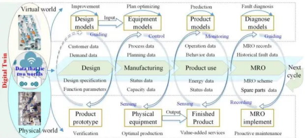
The digital twin is composed of three components: the physical entities in the physical world, the virtual models in the virtual world and the connected data that ties the two worlds (Fig. 2.1[22]). Digital twin reflects two-way dynamic mapping of physical objects and virtual models[24], specifically it is the virtualization of physical entities. The physical operation process is judged, analyzed, predicted and optimized in virtual means. Corresponding, it is the materialization of virtual process.[22]. After the simulation and optimization of product design, manufacturing and maintenance process, it guides the physical process to perform the optimized solution[25].
Data is an inevitable trend in the process of interaction between reality and virtual, the transmission of real-world data to the virtual models is made through the sensors to complete the simulation, validation and dynamic adjustments, after this process the simulation data are fed back to the physical world to respond to the changes, improve the operation and increase the value[22].
2.2 - Digital twin in manufacturing 9
2.2.1 - Applications of Digital Twin
As shown in Figure 2.1[22], digital twin interacts and integrates all the manufacturing processes, which can achieve the closed loop and optimization of the product design, manufacturing, Smart Maintenance, Repair and Overhaul (MRO), etc. [25]
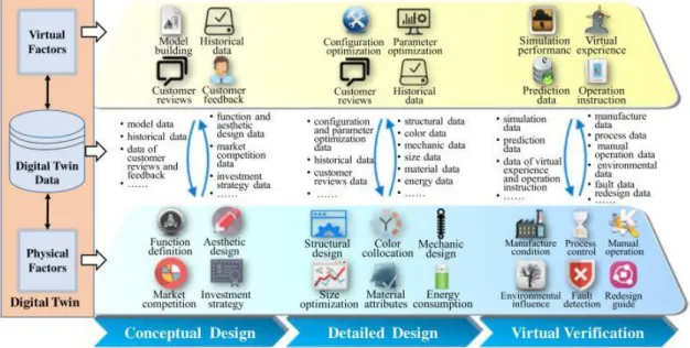
1) Digital Twin Based Product Design - It is well known that the product design process refers to the entire process of a specific design from start to finish and the work steps of every stage it contains. Traditional product design process takes professional knowledge and experience of the individual as the center[25]. Nowadays, in the design phase, it involves back-and-forth interactions between the expected, interpreted and physical worlds, and the based digital twin , the digital representation in the virtual world, of the physical product, the virtual models reflect both the expectations of the designer’s mind and the practical constraints in the physical world [22]. Digital twin based product design enables, just like it is possible to see in Figure 2.2[25] the iterative optimization of the design scheme to guide the designers to adjust their expectations and improve the design models, in addition, digital twin driven virtual verification can quickly and easily forecast and verify product functions, behavior, structures and manufacturability[26].Taking this advantages of digital twin, it’s possible to accurately find defects of design in the virtual world and take quick changes, which make the improvement of the design, avoiding massive and tedious verification and testing.
2) Digital Twin Manufacturing - After the design, the tested product is input into the smart workshop or factory to be manufactured. From the input of raw material to the output of finished products, the whole manufacturing process is managed and
10 Literature Review
optimized through digital twin[27]. The virtual workshop or factory include the geometrical and physical models of operators, material, equipment, tools, environment, etc., as well as the behaviors, rules, dynamics models and others[28]. Before the manufacturing of the products, the manufacturing resources and capacities are allocated, and the production plan is devised to predefine the manufacturing process, the digital twin workshop simulate and evaluate the different manufacturing strategies and planning until a satisfactory planning is confirmed, after input this data and start the real-world manufacturing, the virtual models update themselves based on the data from the physical world to keep aware if any change is required[22].
3) Digital Twin Product Service - The product service described refers to the phases after sale, including product utilization and maintenance phases. In the two phases, users are mainly concerned with reliability and convenience of product, while manufacturers are mainly concerned with real-time product operation state, maintainability, when to maintain, what strategies to employ, etc.[25], so the virtual model of the product is created to establish the product digital twin, this one would always keep in company with the product to provide the value-added services[29]. While the product is monitored in real time, the digital twin continually records the product usage data, use environment data, operating parameters, etc. After that, the virtual model can simulate the operation conditions of product in different environments, this way, it can confirm what effects the different environmental parameters and operation behaviors would have on the health, lifetime and performance so as the to control the status and behaviors of physical product[22]. Finally, based on real-time data from the physical product and historical data, the digital twin product can accurately predict the product remaining life, faults, possible causes of failure, etc.[30] 4) Digital Twin to enable smart MRO – Accordingly to the prediction for health
condition, remaining life, and faults, the proactive maintenance is carried out to avoid the sudden downtime. Furthermore, when a fault occurs, the ultra-high-fidelity virtual model of the product, the fault would be visually diagnosed and analyzed[31]. Thereby, the MRO strategies (e.g. disassemble sequence, spare parts and required tools) are developed to recovery the product. First, before starting the real MRO, the walkthrough about the MRO strategies would be executed in the virtual world based on virtual reality and augmented reality, so, since the mechanical structure of the parts and the coupling between each other are trustfully reflected by the virtual models, it can identify whether the MRO strategy is effective, executable and optimal[22].
2.3 - Simulation modelling 11
In conclusion, and following the Figure 2.1, all the data is together in the digital twin, from all aspects of product lifecycle, laying the data foundation for innovative product design and the quality traceability, therefore, the digital twin promotes an efficient synergy between all the different stages of product lifecycle, achieving the iterative optimizations. Furthermore, the digital twin reduces the product development cycle, enhances the manufacturing efficiency and ensures the accuracy, stability and quality of the entire process[22].
2.3 - Simulation modelling
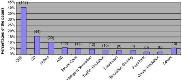
The suitability and relevance of simulation techniques is an important factor to consider in practical real-world applications, particularly as there is a growing need to address the complexities of entire factories and the difficulties of dealing with different layers of decision-making within a system, which is now possible to simulate thanks to the evolution of computer technology[32]. Simulation is recognized as the second most widely used technique in operations management, being the most popular “Modelling”[33]. According to (Jahangirian , et. al , 2010)[32], in the 10 year period 1997-2006, the number scientific papers published regarding simulation applications revealed that DES, System Dynamics(SD) and Agent-Based Simulation (ABS) are the three, single technique, more commonly used for manufacturing and business (Figure 2.3[33]).
12 Literature Review
2.3.1 - Agent-Based Simulation
ABS is described by (Sanchez, 2002)[34] as a simulation made up of agents, objects or entities that behave autonomously. These agents are aware of, and sometimes interact with, their local environment through simple internal rules for decision-making, movement and action, which means, ABS are models where multiple entities sense and stochastically respond to conditions in their local environments, mimicking complex large-scale system behavior, such as vehicles and pedestrians in traffic, people in crowds, artificial characters in computer games, or in this case, simulate a workshop or factory.
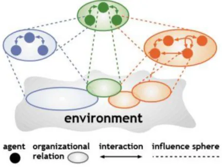
Figure 2.4 - Generic Scheme of a multi-agent system
An agent is a computational system that is situated in a dynamic environment and is capable of exhibiting autonomous and intelligent behavior, the agent have an environment that can include other agents, in this case it is called a multi-agent system[35], example shown in Figure 2.4[35]. These agents have some important computational properties, such as[35]:
• “Agents act on behalf of their designer or the user they represent, in order to meet a particular purpose.
• Agents are autonomous in the sense that they control both their internal state and behavior in the environment.
• Agents exhibit some kind of intelligence, from applying fixed rules to reasoning, planning and learning capabilities.
• Agents interact with their environment, and in a community, with other agents. • Agents are ideally adaptive, i.e., capable of tailoring their behavior to the changes of
2.3 - Simulation modelling 13
Developments in various agent technologies are still extremely dynamic, innovative and ramifying. At the same time, there is also a strong commitment to convergence with current industrial software technologies[36]. Although the agent-based approach allows for an open- ended design and implementation of complex systems, the problems associated with them cannot be solved by less effort, and scalability, while safety and traditional software quality are serious bottlenecks, the main barriers for the industrial take-up of agent technologies are the risk of consistent global operation, the appearance of inevitable conflicts between self-interested entities, and the extra burden of communication. Until recently, the industrial acceptance of multi-agent systems in manufacturing has been relative low, partly because of the above issues, and partly because of the difficulties in their stepwise integration[35].
2.3.2 - System Dynamics
As John Sterman said: “System dynamics has repeatedly been demonstrated to be an effective analytical tool in a wide variety of situations, both academic and practical, and is currently being used by several corporations, including Fortune 500 firms, both in the United States and worldwide. Many of the applications of system dynamics, in both academic research and consulting, involve the quantitative assessment of the costs and benefits of various programs, both retrospectively and prospectively.”[37] But how do people learn about complex dynamic systems? “Learning is a feedback process in which our decisions alter the real world, we receive information feedback about the world and revise the decisions we make and the mental models that motivate those decisions.”[38]
Considering the case of a manufacturing system, as a stochastic nonlinear dynamic system, where it constantly faces the challenges of unpredictable changes (e.g. market demand changes) and random disruption events such as machine random failures, material shortages, labor absentees, etc.[39], an optimal solution to a decision regarding this system would be obtained from a highly combinatorial method, and in such cases a computational approach may not be the most suitable and it’s right here where SD enters. The interaction between system’s agents create a complex behavior which is called dynamic complexity, which arise due to the nature of the system: dynamic, nonlinear, tightly-coupled (everything is connected), adaptive, etc.[40]
SD can be applied from an easy “The Beer Distribution Game” or very complex problems, as seen in [41] and [42], and even if the models are not easy to develop, when a practical model is obtained is easy to simulate it with various inputs, rates and scenarios[43]. SD models have already been used to simulate scenarios that include the impact of corporate decision making or governments, waste water management[44] or even mining[45].
This analytical tool is seen as strategic and holistic[46], continuous and deterministic[44], non-linear and explicit[47], feedback oriented[48] and can suit to policy makers[46].
14 Literature Review
DES and SD have been compared before[46], [47], [49], and even if the approach used in each technique is different, their use together is complementary in some situations with each offering different strengths[47].
2.3.3 - Discrete Event Simulation
As stated in [50] “the modeling of systems in which the state variable changes only at a discrete set of points in time”. With this simulation technique it’s possible to develop simulation models using numerical methods, which make use of computational procedures to solve mathematical relationships that describe the system, it can be events, entities, activities, etc. DES are applied, generally, on a more operational level, while not always being the most adequate approach when addressing certain strategical issues[51], so, it can be applied in various operation management application scenarios, such as scheduling, inventory control or management.
In [52] it is used a combination of optimization methods (specifically, meta-heuristics) and a DES to improve the efficiency of a flexible manufacturing system, regarding a scheduling problem consisting of machine operations and vehicle transportation (vehicle scheduling problem). but DES has a considerable downside, which make it unsuitable to use as a solution for some, DES utilization cannot determine the stability of a system in the near of the determined values obtained after the simulation[53].
Although it is widely used nowadays in numerous cases, DES’s are generally known to be operational, analytical and more suited to decision-makers at the operational or tactical levels[46], [49], discrete and network-oriented[46], stochastic[19], [46], as well as open-process structured[54].
Chapter 3
Simulation Modeling Design
3.1 - Definition of the problem
With the current industry aiming to improve and adapt as fast as possible, Industry 4.0 is spreading around all kinds of places, from hospital networks[55] to manufacturing[25]. The first step is narrow down the possibilities of simulation that’s required. This thesis focusses only in the manufacturing section of Industry 4.0 and all the benefits that’s possible to achieve with a simulation framework.
One of the principles of this dissertation is to develop a new simulation framework, it requires that this framework can do something not yet existing in the market, even if the programing of the new one can be based on a pre-existing software or library, the new feature introduced with this simulation framework needs to be absent from other technologies available. After consideration the two main possibilities to choose from are:
a) a new kind of simulator that with a simple interactive interface can create a new autonomous warehouse with n*m*o (width*height*depth) and x AGVs;
b) a user interface based on current technology software like Excel or a pre-existing language like XML, to auto create a new shop-floor, work schedules, routes, setup-times and everything else needed to simulate a manufacturing system.
3.1.1 - Challenges and approaches
The two possibilities, a and b, present different challenges from a programing point of view and for that same reason it needs different approaches to solve these challenges.
a) Simulate a warehouse with a given number of AGVs requires excellent knowledge in collision routes, choose an object-oriented programming language, choose an interface framework, it needs to run in a reasonable amount of time, with a limit of a few minutes or in the worst case scenario, with an warehouse that needs a lot of iterations to simulate, always less than an hour , because the warehouse should integrate on a manufacturing shop-floor, which itself already takes from seconds to few hours to simulate depending on the complexity of the factory a list of entities, a timeline to organize the events and a mechanism to read these same events(all the
16 Simulation Modeling Design
elements actually used on the simulator will be described further ahead on this dissertation).;
b) Auto create a factory from a file requires an object-oriented programming language that can integrate this feature of reading a file, choose an interface framework where the user can have some liberty to choose from the options available, the file need to contemplate all the usual elements of a shop-floor like sources, sinks, workstations, conveyors and buffers and some user options regarding the date when the factory starts to operate, for how long, if the workstations should or not implement a change-over matrix for the setup time, a list of entities, a timeline to organize the events and a mechanism to read these same events (all the elements actually used on the simulator will be described further ahead on this dissertation).
3.1.2 - Choice and argumentation
Considering the option to simulate an autonomous warehouse an excellent mind and programing challenge, it is still needed to create a factory that can integrate this same warehouse to see its capabilities and to fully test if it is working properly and within reasonable timeframes, which requires to create a shop-floor simulator. Giving the timeframe this dissertation must follow and since the shop-floor will always need to be simulated, the option b, to auto create a factory from a file, it’s the most tangible option to follow and try to accomplish this with the vast options that can integrate a factory is a challenge and a big ambition to follow.
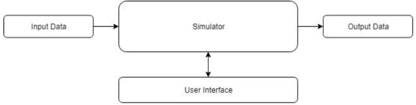
3.1.3 - Initial concept
With the choice made the simulation framework concept needs to integrate three big factors, the simulator model, the input/output data and the interface.
With this concept it’s possible to know some aspects of the simulator, it will be independent of the user interface and the methods to input and output data from the simulation itself, the simulator will get the input data from an outsource block/package and
3.2 - Solution Review 17
output it to other outsource block/package, while in simulation the user will have an interface that interacts with the simulation.
3.2 - Solution Review
The concept of the simulation framework is created, but the possible languages, libraries, pre-existing code or previous frameworks to create this new framework need to narrow down and some choices need to be made even before the simulator starts to the constructed.
3.2.1 - Object-oriented programming language
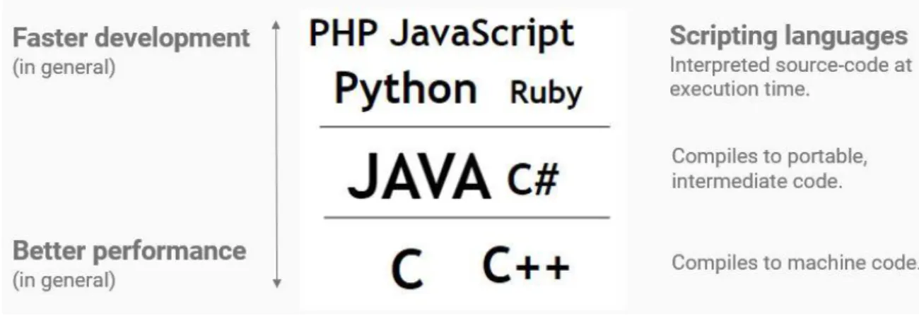
When deliberating about the programming languages options, there is one aspect of the simulation framework that needs to be always present, it needs to somehow be competitive in terms of performance versus the current technologies available, but at the same time it needs to be fast to develop since the dissertation has a schedule to follow, which roles out the top and bottom languages, leaving Java and C#, both object-oriented programming languages. Regarding those two object-oriented programming languages a furthermore research was needed to decide in which one the simulator should be built. “For sure the Java implementation is straighter, and easier to understand without preparation. But of course, it has also drawbacks, for example that the programmer has to do the right thing every time again...”[56]. Another aspects to be concern is the fact that this simulator will feature a Graphical User Interface(GUI), which will require some framework that works well with Java and/or C# and an easy way to create libraries or use pre-existing ones to input and output data to/from the simulator.
18 Simulation Modeling Design
3.2.2 - Graphical User Interface
About the GUI options to the pre-selected object-oriented programing languages, there are GUIs that stand out for each language, Windows Presentation Foundation(WPF)[57] for C# and JavaFX, Swing and Abstract Windows Toolkit (AWT) for Java[58].
The C# GUI, WPF, is straightly for Windows users, it can be an advantage and it is easy to code, but it is Operating System (OS) dependent, which is a downside versus Java.
The Java GUIs, JavaFX and Swing, are not OS dependent and with all the open-source code available for Java, and new code being freely released every day, it’s in reach to get samples of code that will be required to build the user interface.
Here it is found a major difference between Java and C#, the OS dependency, which will rule out C# from further consideration. Considering that Java will be the language that the simulator framework will be built, another advantage versus some of the technologies available on the market, specially SIMIO, has been found, SIMIO doesn’t natively works on Mac or Linux, and with a Java application being built as a new simulation software, it has an advantage of compatibility cross various OS, such has Windows Client, Windows Server, Linux, Linux on ARM, OS X and any virtual machine as long it is supported by a certified hypervisor, like Oracle VM, Virtual Box or Solaris Containers but not supported by VMware because it is not a certified hypervisor[59].
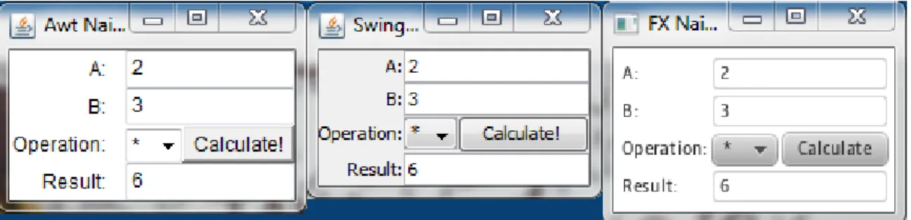
Regarding the GUI options for Java it is quite easily to choose from the available options. When Java was introduced, AWT bundled GUI classes in a library, which was fine for developing simple GUI, but AWT is prone to platform-specific bugs, which later was replaced with Swing, a more flexible, robust and versatile library. The Swing components depend less on the target platform and are directly painted on canvases using Java code. With the latest version of Java, Java 8, Swing is being replaced by the completely new GUI platform named JavaFX[60]. JavaFX brings new features and properties like binding, where a target object can be bounded to a source object, which in the simulation framework case it is an interesting feature to explore due to the connections between the different shop-floor objects. One more aspect considering the GUI is the clean visual aspect, since the JavaFX was the latest GUI to be introduced, as expected, it has the most clean, user-friendly and recent visual of the three GUI options as can be seen in Fig. 3.3.
3.2 - Solution Review 19
3.2.3 - Input/output data stream
The input/output data stream needs to be easy to comprehend and with easy access for the user, that may or may not know how to code, for that same reason it’s required to have an external file, user-friendly, to store all the data needed to create and run the simulation of the manufacturing system. With this, is stated three main options to organize and present the information to the common user (the ones that doesn’t know how to code in any language), Word (.docx), XML and Excel (.xlsx).
A .docx file, even if it may be more appealing to the user due to the common use of this tool, from a programming and performance point of view it would imply serious delays on the program. Word is organized in a way that may bring some difficulties to search for tables or specific values within the given file, if the factory has a lot of model, time or route elements, which can utterly jeopardize the system integrity and performance, even if it is possible to split the different components or time properties of the factory in different files it would create a not very well organized program, so even if the .docx is an effective file, due to is lack of efficiency it was withdrawal from the options.
As stated by Microsoft in their Developer Network website[61], after 2007 with the introduction of Excel version 12.0, and consequently the .xlsx files[62], this files are essentially “Some parts [ISO/IEC29500-1:2012]) store information by using XML and other parts [ISO/IEC29500-1:2012] store information by using binary data.”[61], and mainly because of this new property of the Excel files, it is now possible open then in Mac (OS X) easily and without restrictions[62], which, due to the vast users know what Excel is and how to use it is the most prevalent choice to store the input/output data from our manufacturing system.
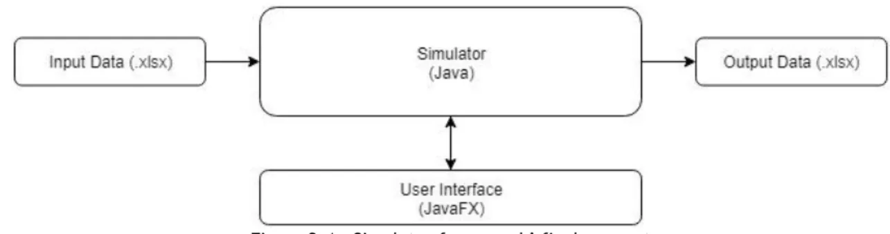
3.2.4 - Final concept
Since the main starting decisions to begin build the simulator framework are done, a new updated concept of the it is provided in Fig. 3.4.
Figure 3.4 - Simulator framework’ final concept
This already considers the options made regarding the language, GUI interface and input/output data stream to start building the simulator.
20 Simulation Modeling Design
3.3 - Proposed Solution
Following the concept of the Fig. 3.4, there are 4 main blocks in the simulator framework architecture, Input Data, Simulator, User Interface and Output Data, all of them with unique features and characteristics that will be described ahead, but first it is necessary to know what model elements are used in the simulator, like sources or sinks, and the ones who aren’t used and why.
3.3.1 - Simulator block
The simulator is a complex program that needs to read events in a specific order and execute them, if possible, to keep the simulation running. Some of the most notorious examples are the basic model components, like sources or sinks, events and a timeline, and other components. The packages that are present in the simulator are calendar, entity, event, exception, layout, model, routing and utilities, the main packages or elements will be further discussed during this chapter. To understand the following sections, it is needed to define an entity, one of the most important definitions - a product or family of products or a raw material, created/released/dispatched by a source that will be moved across the shop-floor.
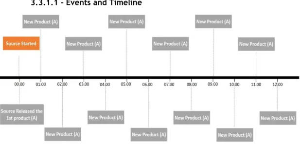
3.3.1.1 - Events and Timeline
Events are the most important element to build a DES, they need to be arranged in a timeline or calendar and needed to be read from a specific order (chronological).
In Figure 3.6, it is shown an example of a source starting at 00h00min. and releases or arrives a new product named “A” every hour. In this 12-hour period every box except the
3.3 - Proposed Solution 21
“Source Started” is an event that needs to be put in the timeline in this specific order and needs to be read chronologically, but somehow jumping from one event to another, which in layman’s terms means that the blank spaces between each event are ignored, since this simulator is a DES, it will only process events and not the blank spaces with zero events. So, an event in this simulator is any action or attempt of action that will have a timestamp and a duration, which essentially means that any event with a start and finish time, like an entity being process at the time x and finish at the time x+n will, in this simulator, generate two distinct events, one to start, if possible, at x, and another event to finish at x+n, so if no other event is in the middle of this two, the simulator ignores the time between x and x+n which saves processing time to the simulator and applies the definition of Discrete Event Simulator.
Events storage and organization:
The Event class has three values associated with each element of this class, a timestamp (the simulated time where it will be store in the timeline), createtimestamp (the time in the real world when was created the event) and an eventNr, the first event has the number 1, the second has the number 2 and so on.
The EventTimeline (the timeline that stores the events) have two main lists, a normal array list that stores all the events that have been already process and a priority queue of events. “The elements of the priority queue are ordered according to their natural ordering, or by a Comparator provided at queue construction time, depending on which constructor is used.”[63], in this case, the events implements a comparator, the first iteration compares the event timestamp, if there is other(s) event(s) with the same timestamp, the second iteration of the comparator sort them by the eventNr, where the first event created have priority in the queue over the second event created with the timestamp. This arrange is just because the simulator only processes one event each time, even when there are multiple events occurring at the same timestamp, which means that all the events with the same timestamp will occur in that timestamp but not all at the same real time.
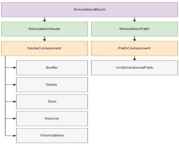
3.3.1.2 - Basic model components
The basic model components are the representation of the usual physical stations or points of interest found in a conventional factory (further details ahead), they are separated in two major groups the NodeComponent that represent the stationary objects like Buffer, Delay, Sink, Source and Workstation, where an raw material or product or entity, can stay for a period of time, and in some cases have changes in this station, like in Workstation, and PathComponent that represent the generic conveyor, named UniDirectionalPath, that connects a point A to a point B within a period of time, like the
22 Simulation Modeling Design
name suggests it only connects the point A to a point B and not vice-versa, to connect the point B to point A it is required to create another UniDirectionalPath. The NodeComponent is a class that implements SimulationNode and the PathComponent is a class that implements the SimulationPath, both extend the SimulationBlock, which is an interface.
The definitions used that characterize the basic model components are:
• Buffer – represent a space in the shop-floor that stores products or entities, it has a label and a capacity, in units, associated to each buffer;
• Delay – it is an abstract representation of a class needed to delay the starting process of a workstation. Every time a workstation has a fixed setup time or a change-over matrix, this is the class responsible to manage the times to secure the transitions between entities are done within the pre-given times. • Sink – represent the end of the line for a product or entity, usually a
shop-floor only have one, but in cases that require multiple exit points this is the representation of that final step, after entering here a entity is destroyed from the simulation, in the physical world it can represent, for example, a
3.3 - Proposed Solution 23
truck or a warehouse where we don’t need to monitor the entities anymore, if we do need to monitor it, it is recommended to use a buffer instead;
• Source – this class represents the entering point to the simulation, when a product arrives to a factory in the physical world it can be from a warehouse, a loading truck, a worker, it is simplified as a “Source” and has a time interval between the delivery of new products or entities to the simulation and will only deliver these new products within a timeframe selected by the user.
• Workstation – is the physical space where a process is being applied to a product or entity, it has an input and output buffer associated with it (which can have zero capacity), if set by the user, it has as delay that represents a fix setup time or a change-over matrix setup time.
3.3.1.3 - Other Important simulator elements
There are other elements that still need to be characterized and described to a full understanding of the simulator architecture, they are:
• ProductMix – or ProductmixEntityGenerator, the name of the class, when a user defines a source, it can create/release more than on type of entity, which means it is possible to create a product mix, with a label for each entity and a value/probability for that same entity.
Table 3.1 - ProductMix example
Product Mix Label Probability
A 30
B 15
When the program reads the product mix, it will standardize the probabilities with a class named Oddbasedrandomizer of each entity, in this case the probability of A is:
P(A) = (30 *1) / (30 + 15) = 0.66(6) ≈ 67%
This is the probability of the source to create/release an entity A in each cycle.
• Routing – this is a package responsible for all the operations regarding an entity’s routes, from each step possible, to prioritize some steps over others according to the user pre-defined priority. This package not only stores all the possible steps that need to be made for each entity, but it manages them with a priority, which means, with this strategy of
24 Simulation Modeling Design
organization it is possible to simulate alternative paths for the same entity, commonly known as graphs or trees;
• Dispatching – one characteristic that hasn’t been developed in this simulator is the appliance of different dispatching rules, with only one available for now First-In-First-Out (FIFO). Fig 3.7. represents a model that uses an example of a FIFO dispatching rule:
Figure 3.7 - Model example to explain a FIFO dispatching rule
In this example, it will have 3 different entities, A, B, C and all of them go from Source to Buffer, A goes from Buffer to WS1, B goes from Buffer to WS2 and C goes from Buffer to WS3, after processing all of them follow the path to the Sink. After some time, the Buffer has 2 entities A, one goes to the WS1, and the other one stays in Buffer, the Source now delivers an entity B, it is stored in Buffer, but since WS2 is free, even if the entity A got there first, when a resource is available, WS2 in this case, and an entity is available to go there, the entity carries on. This means a FIFO rule doesn’t imply who gets out of a resource first, but it orders who enters a resource first. In our example the entity A that got to the WS1 first, was the one who got in first place to the Buffer. This same FIFO rule is applied to the simulator;
• StartingTime – is the simulated date and time where the program should start the simulation, for example, even if it is 2018, the program can be set to start the simulated date and time in May 1st of 2001 at 12:00. The
default value for this StartingTime (if the user doesn’t define it or chooses the InitialTimestamp = 0) it will set the simulated date and time to be January 1st of 1970.
• Oddbasedrandomizer – this class uses the RandomUtils library, which is an “Utility library that supplements the standard Random class.”[64]. “An instance of this class is used to generate a stream of pseudorandom
3.3 - Proposed Solution 25
numbers… If two instances of Random are created with the same seed, and the same sequence of method calls is made for each, they will generate and return identical sequences of numbers.”[65] about the Random class. The peculiar thing about the simulator, as it is right now, it hasn’t a defined seed, which means that every time a simulation starts, even if it is the exact same case study running two times in a row, it can produce different results. A way around this is setting the random seed to be the StartingTime (since it is a fixed value), and in this case doesn’t matter how many times the user runs the simulation, it will produce the same results, but when the user wants the Source to be purely random and acquire different results in each simulation, the user shouldn’t set a seed.
3.3.2 - Input Data block
The Input Data block is straight forward, the simulator needs simulation blocks, timers, routes, some programing options and a product mix, that is exactly the information that the ExcelReader.java needs to get.
26 Simulation Modeling Design
Since the ExcelReader.java implements both interfaces DataModelReader and RoutingReader, not all the methods from ExcelReader.java are listed in the UML, only the most important ones and that need further explanation or exemplification.
3.3.2.1 - DataModelReader
This interface was created in a way to keep further development of the simulator framework easy to integrate, this ensures a way that, in the future, other types of files can be added to the program if they implement the methods stated in Fig.3.8. For now, the DataModelReader has two ways of acquiring data, from the ExcelReader.java or from a static model that is hard codded in the packaged named StaticModelReader.java, but this class is only used for small tests to the simulator, being the ExcelReader.java the focus of this dissertation regarding an input data stream method.
The ExcelReader.java has to implement the method initializeComponents(), which is responsible to update several information’s crucial to the simulator block, in the following examples is shown the method name, table or image, similar to the one found in the excel file, and, when needed, explanation of each cell, to exemplify each of the information required to the simulation to run:
• readPrograming();
Table 3.2 - Programing Options example
Programing Options
Duration
(sec.)
Duration
(days)
Duration
(h.)
Duration
(min.)
InitialTimeStamp
Conveyor
(m/s)
Setup
2073600
24
576
34560
0
0.6
true
The readPrograming() needs the duration of the simulated time in seconds, sometimes it can be a big number, so it is included an option to the user to set it in days/hours/minutes and the excel will make the conversion to seconds, the initialTimeStamp is the date when the simulated time should start, the conveyor speed in meters/second (m/s) and an option for the user to decide if it is needed to read the changeover setup time matrices or not; • readProducts();
Table 3.3 - Product Mix example
Product Mix
Product Type
Probability
A
20
B
20
3.3 - Proposed Solution 27
• readSources();
Table 3.4 - Source example
SOURCES
Label
Duration
TimeInterval
InitialTimeStamp
Source 2073600
540
0
The readSources() assigns a label to each source, a duration (which can be different from the programing options), a TimeInterval between each entity created, and the date/time when the source should start working, in this example is 0, which means it will start when the simulation starts running. • readWorkstations();
Table 3.5 - Workstations example
WORKSTATIONS
Label
Avg.
SetupTime
(sec.)
Avg.
ProcessTime
(sec.)
BufferInCapacity BufferOutCapacity
WS1
1110
468
0
0
WS2
1170
348
0
0
The readWorkstations() assigns a label to each workstation, an average (avg.) setup time and avg. process time, in sec., for when the user doesn’t define a changeover setup matrix, or a setup/processing time in the route of a given entity, as well as buffer capacities, both on entrance or exit of the workstation.
• readSinks()- only requires to assign a label for each sink; • readBuffers();
Table 3.6 - Buffers example
Buffer
Label
Capacity
Buffer1
10000
Buffer2
10000
The readBuffers() assigns a label and a capacity for each buffer; • readConnections();
Table 3.7 - Conveyor example
CONVEYOR
Label
From
To
Capacity
TravelTime
Lenght
Conv_1
Source
WS1
1
13.33
8
Conv_2
WS1
Buffer1
1
10.00
6
The readConnections, is the method responsible to create conveyors, or UniDirectionalPath, between different nodes in the manufacturing system. Every conveyor has an assigned label, from where it connects to a destination,