C
ONSIDERATIONS OF WAVE
-TRANSMISSION FROM SOIL INTO
STRUCTURE BASED ON NUMERICAL
CALCULATIONS
A
NDRÉA
NTÓNIOS
ILVAN
EIVADissertação submetida para satisfação parcial dos requisitos do grau de MESTRE EM ENGENHARIA CIVIL —ESPECIALIZAÇÃO EM ESTRUTURAS
Orientador: Professor Doutor Raimundo Moreno Delgado
Tel. +351-22-508 1901 Fax +351-22-508 1446 [email protected]
Editado por
FACULDADE DE ENGENHARIA DA UNIVERSIDADE DO PORTO
Rua Dr. Roberto Frias 4200-465 PORTO Portugal Tel. +351-22-508 1400 Fax +351-22-508 1440 [email protected] http://www.fe.up.pt
Reproduções parciais deste documento serão autorizadas na condição que seja mencionado o Autor e feita referência a Mestrado Integrado em Engenharia Civil - 2010/2011 - Departamento de Engenharia Civil, Faculdade de Engenharia da Universidade do Porto, Porto, Portugal, 2011.
As opiniões e informações incluídas neste documento representam unicamente o ponto de vista do respectivo Autor, não podendo o Editor aceitar qualquer responsabilidade legal ou outra em relação a erros ou omissões que possam existir.
Este documento foi produzido a partir de versão electrónica fornecida pelo respectivo Autor.
À minha família
…é meu ofício e exercício andar pelo mundo endireitando os tortos e desfazendo os agravos. D.Quixote, XIX
ACKNOWLEDGEMENTS
This work was supported and carried out in the Department for Environmental and Emission Protection, iC-Consulenten, Vienna. During my stay, I have been fully supported in the elaboration of my thesis and in the adaptation to the company and city by all the people around me. This support is gratefully acknowledged.
The Department for Environmental and Emission Protection, iC-Consulenten has important tasks as consulting problems related with issues of noise and ground vibration generated by train traffic. When is intended to construct new buildings near a rail line the issues inherent to the train operation may need to be carefully assessed. The ground-borne vibration, due to the train traffic, may cause problems in occupants’ health and comfort in cases where those limits are exceed, requiring measures to control it. One current countermeasure applied in the receiver (foundation slab) is the polymer material, the resilient bedding for buildings. However, this material presents an important shortcoming: the high costs of the material and its application. In order to find an effective and cheaper solution to solve this problem, or at least in cases where the ground vibration felt doesn’t justify the application of such expensive countermeasures, Michael Österreicher proposed for my final thesis the study of the effect of the foundation geometry slab on the reduction of ground vibration, in order to find potential advantages with the slab foundation geometry.
Finished this report I would like to express my deep and sincere thanks to all people that somehow contributed in the elaboration of this report. Individually, I want address my thanks:
To Michael Österreicher for all help and availability that he offered anytime I needed for the elaboration of this thesis. His contribution was, with no doubt, fundamental for the achievement of the conclusions here presented. To understand the issue of ground vibration generated by train traffic and be able to handle the FLAC software I relied on his knowledge and experience. For that reason, I want to express my admiration for his knowledge and competence that he holds in this type of problems.
In the non-professional aspect I want to thank him too for his efforts to help me in the adaptation to the company and Vienna.
To Professor Raimundo Delgado, who despite the distance he always helped me whenever I needed.
To Mr. Wolfgang Unterberger for having accepted me in his department. I am sure that opportunity he offers me will be very important in my Civil Engineer career.
To Nuno Santos and João Travanca, for the support and material they provide.
ABSTRACT
The implementation of new communication networks in sensitive areas (densely populated, environmental protected areas, etc.), or the construction of new buildings near transportation routes reveals to be often a complex problem. Despite the potential benefits that new communication networks can bring for a given region, it is frequent the opposition from the population to new routes crossing their region. Such feeling is due to the deterioration of life quality that the operation will bring to those residents. Pollution, visual impact, noise, vibration are some aspects that contribute for the discomfort of the population.
Concerning to the train traffic, the noise, the air-borne noise (in the case of tunnels), the noise generated due to the vibration transmitted to the structure and the vibration are the main reasons of discomfort for the population which can be a cause of diseases.
The noise is generated from the contact of the train components and rail reaching the buildings by air. The vibration due to the train traffic results from the transmission of the wheel loads to the ground under and beneath the track, which propagates through the soil till reach the building foundations. In certain situations, the induced vibration by train traffic doesn’t exceed the established limits, however the population claims against the vibration generated by the train traffic. This situation is explained through the phenomena of resonance, where the frequency vibration transmitted to the building can reach the natural frequency of some building components. The effect of “loudspeakers” of walls, with rattling of shelters, shows how this problem is amplified. This phenomenon is called the structural noise or re-radiated noise.
In order to solve this problem there are several solutions which can be applied in the source, in the propagation path and/or in the receiver. The mitigation measures applied in the source are the most common once present the better relation costs/effectiveness. However, when it is intended to construct new buildings near railway lines, in most of the cases is not possible to apply the countermeasures in the source, so the mitigation measures in the receiver should be taken.
A mitigation measure applied in the receiver is the rubber resilient bedding for buildings. This material is applied in the foundation slab and in the sustaining walls. This solution can in same cases reduce the vibration transmitted to the remaining building around 50% of the original vibration. However, the material itself and its application presents a high costs and in certain cases, even requires measures to reduce the vibration measured; so this doesn’t justify the application of such expensive countermeasure.
In order to find a solution that can be economically more interesting, it was made a parametric study of the foundation slab thickness, using the finite differences software FLAC. This study was performed in models 2D and had as principal purpose to find a law that could be used to avoid excess of vibration.
This study concludes that by increasing linearly the foundation slab is achieved a reduction of the ground vibration absorbed in the order of . Thus, for situations where the ground vibration slightly exceeds the limits the solution can pass by increasing the slab. It is a practical and economical option, since the cost of the material resilient bedding and its application present costs around ⁄ and the concrete is ⁄ . For buildings with a high implantation area the costs difference will be important.
KEYWORDS: ground-borne vibration, train traffic, FLAC, foundation slab thickness, reduction of ground vibration.
RESUMO
A implantação de novas vias de comunicação em zonas sensíveis (focos populacionais, zonas de protecção ambiental, etc.), ou a construção de novos edifícios junto a vias de comunicação revela ser muitas vezes um problema complexo. Apesar dos potenciais proveitos que novas redes de transporte podem trazer para determinada região, é frequente assitir-se à oposição da população à passagem de novos traçados nas suas localidades. Tal sentimento de oposição deve-se essencialmente ao deteriorar da qualidade de vida resultante da operação nessas vias de comunicação, tais como a poluição, impacto visual, ruído, vibração, etc…
No que diz respeito ao transporte ferroviário, o ruído transmitido “via aérea”, gerado pelas vibrações da estrutura, e as vibrações são o principal motivo de desconforto para as populações e que podem ser a causa de doenças.
O ruído transmitido “via aérea” é gerado pelo contacto dos material, das peças do comboio, propagando-se através do ar. As vibrações geradas pelo tráfego ferroviário resultam da carga transmitida pelo comboio ao solo envolvente propagando-se por este até alcançarem as fundações dos edifícios. Em determinadas situações as vibrações induzidas nos edifícios devido ao tráfego ferroviário não ultrapassam os limites estabelecidos, no entanto o tráfego ferroviário é objecto de grande contestação por parte da população. Esta situação resulta do fenómeno de ressonância que as vibrações possam produzir em certas partes do edifício. Quando as frequências das vibrações igualam a frequência natural de paredes, estas amplificarão o ruído, funcionando como “altifalantes”. Este ruído é conhecido como ruído estrutural ou “re-radiated noise”.
Com vista a resolver o problema das vibrações geradas pelo tráfego ferroviário existem diversas soluções a aplicar na fonte de vibração, no meio de propagação e/ou no receptor. As medidas aplicadas na fonte de vibração apresentam melhor relação custo/eficácia e como tal são as mais usadas no controlo da vibração. No entanto, em situações onde se pretende construir novos edificios perto de linhas ferroviárias já existentes ter-se-á de adoptar medidas no receptor, isto é, nas fundações do edifício.
Uma das medidas aplicadas nas fundações são as “camas elásticas” que consistem num polímero aplicado na laje de fundação e paredes de contenção. Esta medida revela-se de certo modo eficaz na medida em que reduz até 50% as vibrações transmitidas ao edifício. No entanto, esta medida apresenta custos elevados. Em certas situações as vibrações produzidas, apesar de necessitar de medidas de mitigação, não justificam a aplicação deste material.
Com vista a encontrar uma solução interessante em termos económicos recorreu-se ao software de diferenças finitas (FLAC), para se realizar um estudo paramétrico, em 2D, acerca da espessura da laje tendo em vista as alterações produzidas nas vibração recebidas pela laje.
Conclui-se com elaboração desta tese que incrementando linearmente a espessura da laje poder-se-á obter um redução efectiva das vibrações na ordem dos . Assim para casos de menor gravidade, o incremento da espessura da laje da fundação usando betão corrente poderá constituir uma opção viável e económica. Tendo em conta que o custo e aplicação das “camas elásticas” terá um custo a rondar os ⁄ e o preço do betão é de ⁄ . Para edifícios com grande área de implantação o custo total será muito significativo.
PALAVRAS-CHAVE: vibração induzida, tráfego ferroviário, FLAC, espessura da laje da fundação, redução da vibração.
TABLE OF CONTENTS ACKNOWLEDGMENTS ... i ABSTRACT ... iii RESUMO ... v
1. INTRODUCTION
... 1 1.1.BACKGROUND ... 11.2.OBJECTIVES AND ORGANIZATION OF THE THESIS ... 2
2. STATE OF THE ART
... 52.1.INTRODUCTION ... 5
2.2.GROUND-BORNE VIBRATION DUE TO THE TRAIN TRAFFIC ... 5
2.2.1. VIBRATION SOURCE ... 6
2.2.2. PROPAGATION PATH ... 10
2.2.3. RECEIVER ... 11
2.3.EFFECTS OF VIBRATION ... 11
2.3.1. HUMAN RESPONSE ... 12
2.3.2. VIBRATION IMPACTS ON BUILDINGS ... 17
2.4.MITIGATION METHODS... 18
2.4.1. MITIGATION MEASURES IN THE SOURCE ... 18
2.4.2. MITIGATION MEASURES IN THE PATH ... 20
2.4.1. MITIGATION MEASURES IN THE RECEIVER ... 21
3. DYNAMIC ANALYSIS
... 253.1.INTRODUCTION ... 25
3.2.DYNAMIC MATERIAL MODEL ... 25
3.3.EQUATION OF MOTION ... 26
3.4.RESPONSE OF A SYSTEM UNDER VIBRATION ... 28
3.5.SIGNAL ANALYSIS ... 35
4.1.INTRODUCTION ... 41
4.2.FLACSOFTWARE ... 41
4.2.1. TERMS AND CONCEPTS ... 42
4.2.1.1. Finite Differences ... 42
4.2.1.1. Explicit, Time-Marching Scheme ... 42
4.2.1. NUMERICAL FORMULATION ... 43
4.2.2.1. The Grid ... 44
4.2.2.2. Finite Difference Equations ... 44
4.2.2.3. Time-Step ... 47 4.2.2.4. Mechanical Damping ... 48 4.2.2.4.1. Rayleigh Damping ... 49 4.2.2.4.1. Radiation Damping ... 51 4.3.NUMERICAL MODELING ... 52 4.3.1. ELEMENT SIZE ... 53
4.3.2. DIMENSIONS OF THE MODELS ... 55
4.3.3. IDEALIZED MODELS ... 55
5. EQUIPMENT DESCRIPTION AND MEASUREMENTS
... 595.1.INTRODUCTION ... 59
5.2. DESCRIPTION OF THE INSTRUMENTS USED FOR THE MEASUREMENTS USED WITHIN THE OBJECTIVE WORK ... 59
5.3.MEASUREMENTS CARRIED OUT FOR THE OBJECTIVE WORK ... 61
5.4.RESULTS OF THE MEASUREMENTS ... 63
6. PARAMETER STUDY
... 656.1.INTRODUCTION ... 65
6.2.RESULTS ... 67
7. CONCLUSIONS
... 75APPENDIX A
FLACMODEL DEVELOPED FOR A SLAB 1.0M THICK 60M AWAY FROM THE SOURCE
APPENDIX B
VIBRATION RECORDED IN THE MODELS
APPENDIX C
INDEX OF FIGURES
Fig. 1 – Ground-borne ... 2
Fig. 2 – Distinctive stages of the study of train induced ground vibration ... 5
Fig. 3 – Wave-transmission of ground-borne vibration ... 6
Fig. 4 – a) Train transmission system; b) Wheel forces ... 7
Fig. 5 – Rail fastening system ... 7
Fig. 6 – Effects of ballast pads ... 8
Fig. 7 – a) Ballasted track; b) Slab track; c) Floating slab track ... 9
Fig. 8 – Variation of stress patterns... 9
Fig. 9 – Propagation path ... 11
Fig. 10 – Effects of vibration ... 12
Fig. 11 – Response to residential building vibration 4 to 15 rapid transit trains per hour ... 13
Fig. 12 – Frequency weighting ... 14
Fig. 13 – Health guidance caution zone ... 17
Fig. 14 – Resilient direct fixation fasteners ... 19
Fig. 15 – Ballast mat applicatio ... 19
Fig. 16 – Floating slab track ... 20
Fig. 17 – Wave barriers ... 21
Fig. 18 – Building elastically supported ... 21
Fig. 19 – Countermeasure (CIBATUR) applied in the foundations ... 22
Fig. 20 – Vibration reduction of Cibatur ... 22
Fig. 21 – Application of bedding elastic for buildings ... 23
Fig. 22 – Lateral view of bedding elastic for buildings ... 23
Fig. 23 – Single-degree-of-freedom system ... 26
Fig. 24 – Steady state displacement response ... 29
Fig. 25 – a) Variation of dynamic magnification factor; and b) variation of phase angle; with damping and frequency ... 30
Fig. 26 – Transformation of a function into a periodic one ... 33
Fig. 27 – Measured signal: y-velocity ... 35
Fig. 28 – Frequency spectrum ... 36
Fig. 29 – Propagation of seismic waves ... 38
Fig. 33 – Calculation cycle performed by FLAC ... 43
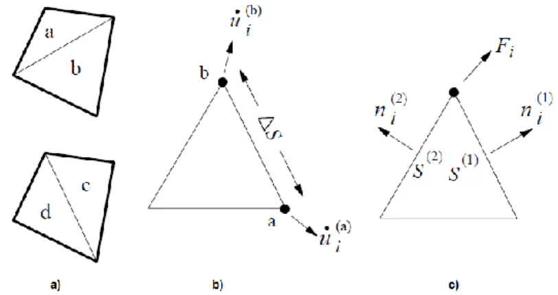
Fig. 34 – a) Overlaid quadrilateral elements in FLAC; b) Typical triangular element with velocity vectors; c) Nodal force vector ... 44
Fig. 35 – FLAC analysis... 46
Fig. 36 – Relation between the damping ratio and the frequency in the Rayleigh damping ... 50
Fig. 37 – Transmitting boundaries: a) viscous boundary and b) elementary boundary ... 51
Fig. 38 – Representation accuracy ... 54
Fig. 39 – Static model ... 56
Fig. 40 – Stress pattern ... 56
Fig. 41 – Dynamic loading ... 57
+2 Fig. 42 – Measurement system VibroStar ... 59
Fig. 43 – The 3-component vibration transducer ... 60
Fig. 44 – An example time history and frequency analysis recorded by VibroStar ... 61
Fig. 45 – Summary plor of all measurements ... 62
Fig. 46 – Summary plot of all measurements – average of amplification factors ... 62
Fig. 47 – Relation between foundation thickness amplification factors ... 62
Fig. 48 – FLAC model with slab 1.0m thick located 60m away from the source ... 65
Fig. 49 – Generation and propagation of seismic waves ... 66
Fig. 50 – Velocity vector maximum values recorded from a model with a slab 1,0m thick located 60m from the source ... 67
Fig. 51 – Variation of ground vibration felt in the slab located 30m away from the source relatively to a slab with 0,5m thick and the correspondent trend line ... 68
Fig. 52 – Variation of ground vibration felt in the slab located 40m away from the source relatively to a slab with 0,5m thick and the correspondent trend line ... 68
Fig. 53 – Variation of ground vibration felt in the slab located 50m away from the source relatively to a slab with 0,5m thick and the correspondent trend line ... 69
Fig. 54 – Variation of ground vibration felt in the slab located 60m away from the source relatively to a slab with 0,5m thick and the correspondent trend line ... 69
Fig. 55 – Average of variation of ground vibration felt in the slab relatively to a slab with 0,5m thick .. 69
Fig. 56 – Variation of ground vibration felt in the slab located 40m away from the source relatively to a slab with 0,5m thick under 200kPa ... 70
Fig. 57 – Variation of vibration frequencies between two slabs 0.5m and 1.0m thick for different distances ... 71
Fig. 58 – Vibration frequencies recorded in the top of the slab, 30m away from the source ... 71
Fig. 59 – Vibration frequencies recorded in the top of the slab, 40m away from the source ... 71
Fig. 60 – Vibration frequencies recorded in the top of the slab, 50 away from the source ... 72
Fig. 61 – Vibration frequencies recorded in the top of the slab, 60 away from the source ... 72
Fig. 62 – Variation of vibration frequencies between two slabs 0.5m and 2.0m thick for different distances ... 72
Fig. 63 – Vibration frequencies recorded in the top of the slab 30 away from the source ... 73
Fig. 64 – Vibration frequencies recorded in the top of the slab 40 away from the source ... 73
Fig. 65 – Vibration frequencies recorded in the top of the slab 50 away from the source ... 73
Fig. 66 – Vibration frequencies recorded in the top of the slab 60 away from the source ... 73
Fig. 67 – Variation of vibration frequencies between two slabs 1.0m and 1.5m thick for different distances ... 74
Fig. 68 – Variation of vibration frequencies between two slabs 1.0m and 2.0m thick for different distances ... 74
Fig. 69 – Variation of ground vibration felt in the slab, 20m length, located 30m away from the source ... 76
TABLES INDEX
Table 1 – Different factors influencing the level and characteristics of train induced ground vibrations10 Table 2 - Time increase due to the utilization of Rayleigh damping in FLAC ... 51 Table 3 – Study models ... 52 Table 4 – Soil properties ... 54
NOTATION
– Daily vibration exposure
– Daily vibration exposure in direction – Weighted acceleration
– Critical damping – Viscous damping ratio
– P-waves velocity – Rayleigh waves velocity – Shear waves velocity
– Dynamic magnification factor – Excitation load – Damping force – Inertial force – Spring force – Shear modulus – Transfer function – High-pass filter – Low-pass filter
– Pure weighting function – Elastic constant
– Bulk modulus
– Coefficient dependent of the direction – Lumped mass
– Excitation load function – Amplitude load – Static defection – Vibration period – Exposure duration ̈ – Ground acceleration – Displacement ̇ – Velocity ̈ - Acceleration
– Poisson ratio
– Critical coefficient ratio – Density
– Angular frequency – Excitation frequency
– Damped frequency – Natural frequency
ANSI – American National Standards Institute DFT – Discrete Fourier Transform
FDM – Finite Difference Method FEM – Finite Element Method FFT – Fast Fourier Transform
FLAC – Fast Lagrangian Analysis of the Continua HST – High Speed Train
ISO – International Standard Organization MDOF – Multi-degree-of-freedom
r.m.s – Root-mean-square SDOF – Single-degree-of-freedom
1
INTRODUCTION
1.1. BACKGROUND
In a society increasingly global the evolution of transportation networks are of critical importance. The numerous air links offered to european customers is a reflex of the politicians took that aim a bigger mobility within Europe and all over the world. With respect to the train transportation, European Union has being promoting different programs to encourage the member-states to build an efficient european high-speed network with interoperability between the different countries to suppress the actual weaknesses of the transportation system of persons and goods. The most recent and serious failure of the actual system happened with the eruption of the icelander volcano Eyjafjallajökull on the year 2010 stopping the air traffic in almost all Europe, causing large amounts of losses.
The extensive investments made by the governments to improve the actual railway system, in new infrastructures to enable the people and goods to move in a modern, sustainable and efficient with reduced costs, incremented the necessity to create more effective railway network and new machines, more powerful and faster. However, the train transportation brings some problems for the railway line neighborhood related with its operation, as the ground-borne vibration, ground-borne noise (in the case of tunnels) and the air-borne noise. These problems become more serious when the railway line crosses sensitive areas as inhabited or environmental protected areas.
In 1847 with the first railways in England between the cities Manchester and London, Sir James South was charged to evaluate the consequences of the passage of trains near the Royal Observatory of Greenwich. The method to evaluate was based on studying the effects of ground-borne vibration caused by the passage of the train at different velocities and to find velocity limits in order to minimize the vibration effects.
Particularly since the 1960s, environmental noise has become an increasingly important issue. Noise is often identified as a source of dissatisfaction with the living environment by residents. With the increasing of noise levels the population became aware of the potential noise impact that new railway lines could bring. Opposition to new projects that can cross their “neighborhood” is the evidence that the populations are afraid to loose life quality.
Fig. 1– Ground-borne vibration (Unterberger, 2004)
Nowadays, new railway projects take seriously the effects caused by the train traffic on the life quality of the populations around the railways, being very important to project the new railway in order to serve the interest of the owner and respect the life standards concerned with air-borne noise and ground-borne vibration. To solve these problems it shouldn‟t be studied separately from each other the different aspects of train traffic, once many times they have a common source and often the countermeasures taken can solve part of the two problems.
As the theme of the thesis indicates, this study will be focused on the problem related with ground-borne vibration. This problem can be subdivided into three categories according the different types of railway situation (Fig. 1): the heavy axle-load freight traffic, travelling at relatively low speeds, causing high amplitude vibration at the track; the high speed passenger trains that travel at speeds higher than the wave speed of vibration in the ground and in the embankment; and the trains running in tunnels which transmit vibration to buildings above and around them. To do the study of ground-borne vibration, the problem should be interpreted in three distinct parts: the generation of waves as result of the interaction between the railway track with the soil beneath while the train passes; the propagation path traversed by the seismic waves; and the interaction between the soil and the foundations of the building.
To perform this study it will be used the FLAC – Fast Lagrangian Analysis of the Continua, developed by Peter Cundall, Itasca Software, in 1986. The code is an explicit two-dimensional finite difference program that performs a Lagrangian analysis.
1.2. OBJECTIVES AND ORGANIZATION OF THE THESIS
The study of the present topic, ground-borne vibration due to the train traffic as mentioned, can be subdivided into three categories. This thesis will be focused in the interaction between soil and the foundation of the building. Using a software developed for geotechnical analysis to perform static and dynamic analysis, FLAC – Fast Lagrangian Analysis of Continua, the influence of the foundation slab characteristics in wave reception will be studied, specially the thickness. The study will be done through the calculation of several models 2D with the slab located along the propagation path. The slab modeled should present a constant thickness along its length. The slab will support a constant
tension that represents the weight of the building. The building itself won‟t be modeling because the FLAC software proved that is not reliable, Travanca [10].
With this report it is expected that in some cases where the ground vibration, due to the train traffic or another source, exceeds the legal limits, a solution can pass by increasing the foundation slab, avoiding this way expensive mitigation measures against the ground vibration, especially the mitigation measures that are applied in the receiver.
For example, the material Cibatur is placed between layers of concrete, significantly reducing the ground vibration. The material plus its application in the foundation slab costs around ⁄ . In cases where isn‟t necessary such reduction, because in the source there are already countermeasures in the source, however insufficient, or the building construction site is located far away that doesn‟t justify an expensive countermeasure. So, with an increase of the foundation slab it is possible to reduce costs of installation and conservation, construction times, etc. So the use of a thick slab to reduce the ground vibration can be an attractive solution, since the cost of material (a of concrete, in Austria, costs around ) and its application would be cheaper and faster. This report expects to answer to this answer.
The organization of the thesis is as follows:
The chapter 1 gives a background of problems caused by train traffic and describes the objectives of the report.
In chapter 2, the aspects related with the ground-borne vibration will be discussed. The three components of the generation, propagation and reception will be analyzed and its influence in all process. The effects of vibration on human response and impacts on buildings are described and the limits imposed by the austrian standards. In the cases which the legal limits are not respected are presented some countermeasures and its application framework.
The chapter 3 will present the fundamental concepts that are important to understand the dynamic analysis. The dynamic material model that was assumed is the elastic, isotropic scheme, since the strain levels produced by the ground vibration due to train traffic are very lower. It is developed the expressions for dynamic analysis and for signal analysis. It is also presented the seismic waves that carry the energy produced by the train traffic.
In the chapter 4 it is presented the study of the ground-borne vibration. Firstly the FLAC software, terms and concepts, as its calculation algorithm is presented. This software presents a finite difference method (FDM) which presents advantages and disadvantages when compared with finite element method (FEM) that it will be explained forward. It is also presented the FLAC characteristics that make it a powerful tool to evaluate the vibration propagation through the half-space as the silent boundaries, Rayleigh damping, etc. Also the models characteristics which interest calculate will be introduced, as the element size, its dimensions and the dynamic load applied.
Chapter 5 presents the material used in iC-Consulenten to do the assessment of ground vibration. Additionally, is presented some resumed data, obtained from measurements done. These results are of extreme importance, since it is based on that it possible to have substantiated conclusion of the model results.
Chapter 6 presents the results obtained. As it was stated before, the aim of this report is to obtain the variation law of ground vibration reception with the variation of the slab thickness, for this reason the results presented are not absolute values but relative values. I.e., the decreasing of vibration reception
when increasing the slab thickness is made in function of a thickness slab of 0,5m, since corresponds to the high value for the 4 thicknesses admitted. The variation of the frequency received for different thicknesses will be also studied in this report.
2
STATE OF THE ART
2.1. INTRODUCTION
It is consensual that studies done about the ground-borne vibration due to the train traffic and the prediction of their influence on buildings, sensible areas or humans within a building can be subdivided in three main “propagation components”, with different complexity according the location, type of train or project phase. These three parts consist of the source, the propagation path through the soil and the receiver and its wave propagation within the building. The generation of vibrations due to the passage of trains on the track line or vehicles on the road is the source; the propagation path corresponds to the path traveled by the waves, from the source to the receiver; the receivers are residential areas, a single building, etc. This chapter consists of a brief review concerning the subject of ground-borne vibration due to train traffic and the importance of each component dealing with this topic.
2.2. GROUND-BORNE VIBRATION DUE TO THE TRAIN TRAFFIC
The wave-transmission from soil into structure is a complex process which involves several factors, many of them are unknown or approaches based on similar cases. The study of the transmission of train-induced ground vibrations can be separated into several distinctive stages; each of them represents its own characteristics to provide an input to the next stage in the process. In the Fig. 2, one can see the different parts concerning this subject. The stages of this process are divided in the source, the propagation path and the receiver. At this step, it is assumed that the distance between the railway track and the building is large enough to consider that the presence of the building doesn‟t affect the vibration generation.
Due to the fact that there are a lot of different train construction types, with various technologies in different states of operation, the relative importance of the components responsible for the generation of waves isn‟t unanimous, and varies according the model and stage of the project.
Also the propagation path, which corresponds to distance between the source, the axis of the railway line, and the receiver, the building foundations, is very difficult to determine exactly in its properties. In finite elements models (FEM), it is usually assumed that the soil is constituted by one or more homogeneous layers. This assumption doesn‟t correspond to the reality. In spite of the use of representative values, there are small volumes of soil with completely different characteristics inducing changes on the comportment of the waves. Due to these uncertainties described above, measurements should be applied to determine the important soil parameters. Usually this is done by seismic investigations (for example refraction seismic).
Fig. 3 - Wave-transmission of ground-born vibration [2]
The receiver represents the inhabited area or special buildings, like hospitals or schools. However, the inhabitants of buildings don‟t experience the ground-borne vibrations with the same severity and sensibility. Although the ground floor (foundation) is the receiver of ground vibration is not necessary the most affected by vibration, since the different natural frequencies of the different floors can cause higher vibrations due to the phenomenon of resonance.
2.2.1. VIBRATION SOURCE
The vibration source mainly consists of the train properties (for example the suspension) and the type and the constitution of the track way itself. On this topic there is a respectable research about the importance of train suspension system, the railway type of construction, the importance of the embankment, the importance of the maintenance, etc. In this section the authors Bahrekazemi [1] and Hall [2] which can provide general notion about the vibration source will be presented.
According to Bahrekazemi [1], the vibration source of the ground-borne vibration due to train traffic is approved as a result of the interaction between the moving train itself and the rail way tracks. To find out how the vibration are generated it is essential to understand how each component of the vibration source works: the interaction between the moving train, the track and the soil mounted on, the load of
the moving train is transmitted through the train suspension to the track and finally to the ground under and around the track.
Fig. 4 – a) Train transmission system [1]; b) Wheel forces [1]
Although there are many types of trains with a different state of maintenance, different technology standards, maximum speed level or the type of traffic, the basic transmission of loads to the track is similar in all of them. The main parts of the train considering the excitation of vibrations are schematically shown in Fig. 4 a). The load of the moving train is transmitted to the bogie through secondary suspension which in the new trains consists of an air bag. The load is then transmitted to the wheels via primary suspension and the wheels in turn transfer the load to the track lines as shown in Fig. 4 b).
The transmission of the load from the track to the ground beneath and around the track line depends of the type on track way ballast. In order to control the ground-borne vibration and the ground-borne noise, different methods have been developed for the construction of the tracks. Its importance has grown following the emergence of trains more powerful and faster reflecting it in new materials, as the case of rubbers, and the installation of sleepers welded.
The different trackway types can be subdivided in two main groups: the ballasted tracks, shown in Fig. 7 a), and the non-ballasted tracks, Fig. 7 b) and c). The ballast track is the most common type of railway technology applied in the railroad networks. In the Fig. 7 a) the rails are held to sleepers which in turn are supported in a layer of stones (ballast). The Fig. 5 shows detail drawing of a typical rail fastening system. The ballast thickness is typically 30 cm to 40cm under the sleepers overlying in subballast which usually is 40 cm. An important component of the track, which has a considerable influence on the rolling noise behavior, is the rail pad. It is made of rubber and is located between the rail foot and the sleepers. These pads have the primary function of protecting the sleepers, particularly the concrete ones, from high impact loads which may cause cracking, and at same time have an important role on vibration and noise reduction of resulted by interaction between the rail and the sleepers, due to their soft stiffness (Fig. 6).
Fig. 6 – Effect of ballast pads
The non-ballast, slab and floating slab track, have been used increasingly in recent years especially in rail way tunnels. Its use reveals to be more efficient in reducing the ground-borne vibration and the noise vibration than in ballasted tracks, due to construction of the track by different layers with different materials which can filter the different frequencies excited due to the passage of the train. The effective reduction of the vibration from the passage of trains and the low maintenance required provided by non-ballasted tracks, as for example the floating slab makes it interesting to install in tunnels and in structures as bridges. However, due to the costs of installation, its implementation should be made only in areas where it is important to have a significant reduction of the problems already enounced.
Fig. 7 – a) Ballasted track; b) Slab track; c) Floating slab track [3]
It is important due to the fact that there are many types of tracks with different types of technology, with increasing costs according their complexity and efficiency, to make an accurate evaluation of the vibrations generated by the passage of trains and the occupation of the area, presently and hereafter, around the line. In the case of track line with no measures against the ground-borne vibration and noise vibration, the construction that will arise around the line will need countermeasures in the receiver (building) that will be more expensive and less effective.
Fig. 8 – Variation of stress patterns (Hall)
The vibration excitation, according to Hall (2000) has as a principal factor: the variations of stress patterns in the ground beneath and around the track caused by the load of the train movement, showed in Fig. 8. A variation of the ground reaction (this mechanism is also called track structure response), caused by the moving stress pattern will induce stress waves, even in the absence of imperfections or periodic irregularities in the vehicle or track (Dawn and Stanwaorth, 1979) jointly with many other sources supplementing vibrations caused by moving stress patterns.
The Table 1 presents different factors which have influence on train-induced ground vibration. This is a collection from several authors brought together by Hall. Some of these features will only produce local effects while others will create a regular stress pattern moving with the train. The extent of these features will depend on the train velocity and its weight.
Table 1– Different factors influencing the level and characteristics of train-induced ground vibrations [2]
Stress waves induced by the track structure response Axle weight
Spacing of wheel axles Speed of train
Vibration source at wheel-rail interface
Unsteady riding of the vehicle (bouncing, rolling, pitching) Dynamic properties of the vehicle bogie
Wheels defects (eccentricity, imbalance, flats) Misalignment of motors
Acceleration and deceleration of train Discontinuity on the track Rail defects (unevenness, waviness)
Spacing and interval of rail joints Switches
Curves and tilting track (centrifugal forces) Variable support
Geometry, stiffness and spacing of sleepers Geometry, stiffness and heterogeneity of the ballast
Stiffness and geometry of the ground
2.2.2. PROPAGATION PATH
The vibration generated in and around the railway track due to train traffic will propagate to the surrounding soil. The geometrical damping, the stiffness and the material damping of the surrounding soil and rocks will determinate the degree and extent spread of the ground vibrations. A variety of waves are induced in the media, but for the purpose of the subject ground-borne vibration the focus is based on the study of compression waves, shear waves and especially the Rayleigh waves. Each of these wave-types has different propagation velocities as well as the particle motion and will diminish differently in intensity with the distance increasing from the source. The propagation of different types of waves is further influenced by reflection and refraction as the propagating waves pass through different materials, as it’s represented in the Fig. 3.
The distribution of ground-borne energy depends strongly on the magnitude excitation and will neither be equal through the space or the types of waves. If the excitation is localized in a small area, compared with shear wave wavelength, the R-waves will carry most of the energy. Wood (1968) proved that 67% of the energy in small areas is carried by surface waves. If, however, the excitation
area is large, body waves will be dominant (Heckle, Hauck & Wettschureck, 1996). The Fig. 9 shows the distribution of the different types of waves [1].
Fig. 9– Propagation path (Woods, 1968)
In the study of railway traffic induced ground-borne vibration most of the energy will be carried by the lower frequency waves: the R-waves. This happens because the dimensions of the embankment are generally small compared with the shear wave wavelength, so the embankment will work as a filter of high frequency waves (Bodare, 1993).
2.2.3. RECEIVER
The foundations of a certain structure works as the receiver of the ground-borne vibrations. The importance of the vibration absorbed by the foundations, as was expect, depends on several aspects, as the type of construction, type of foundations and the type of soil where the foundation is located, respectively. In some soft soils, like soft clays, the vibrations due to the train traffic can be felt at 200 m from the source.
According with Barehkazemi [1], only the low vibration frequencies can be absorbed by the building foundations. From the range of vibration frequencies produced by train traffic, the frequencies between 1-60Hz are potentially absorbed by foundations and transmitted to the remaining structure. The vibration generated due to the train traffic propagates until the building foundations. From the building foundations, the vibration propagates to the remaining structure. The principal objective of this thesis will be focused in the foundation transmission characteristics. It will be discussed the influence of the length and thickness of the foundation slab, with the finite differences software (FLAC).
2.3. EFFECTS OF VIBRATION
Noise and vibration assessments are very important for the environmental impact assessment process for mass transit transports. The ground waves travel through the various soil and rock layers to the foundations of nearby buildings. After being received, the vibrations propagate through the structure. Generally the ground vibrations itself are not the principal problem for inhabited areas. The real
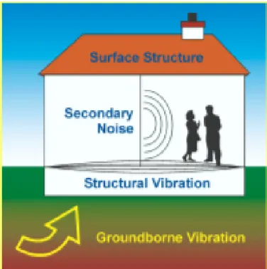
problem occurs when the ground vibrations contents of frequencies which are similar or equal to the natural frequency of the floors and/or walls in buildings. This can on the one hand cause the effect of loudspeaker, the so-called re-radiated noise or structure-born noise, schematized in Fig. 10. On the other hand the vibrations itself can be perceptible. Because of that, the effects of ground-borne vibration due to the train or road traffic make the analysis of the real effect on the occupants inside the building very difficult.
Fig. 10 – Effects of vibration (Unterberger, 2004)
2.3.1. HUMAN RESPONSE
One of the major problems to develop a suitable criteria for assessment of ground-borne vibration is that there has been relatively little research into human response to vibration, in particular human annoyance due to building vibrations. In 1983, the American National Standards Institute (ANSI) developed a criteria which describes a connection between the human response and a measured vibration value. The results basically show that it was not possible to measure the human response based only on the magnitude of the measured vibration. In some cases the occupants of a building complain it, even when the vibration values recorded were lower than a given threshold. The criterion developed by ANSI, make an evaluation of the human response combining the physical aspects of the ground vibration such as amplitude, frequency and duration with psychological aspects related with the population such as gender, age, occupation, etc.
The data represented in Fig. 11, present in DOT–293630–1, illustrates the relationship between the vibration velocity measured in 22 objects and the subjective response of the occupants to the vibration. This data was assembled from vibration measurements connected with subjective ratings by researchers and occupants. The data shown in Fig. 11 indicates that residential vibration exceeding approximately (75dB) is unacceptable for a repetitive vibration source, such as a train that passes every 5 to 15 minutes. Additionally, it shows a curve indicating the percent of people
annoyed by vibration from HST in Japan. The conclusion of this study indicates that a particle velocity over than will find the vibration annoying.
Fig. 11 – Response to residential building vibration 4 to 15 rapid transit trains per hour [4]
The International Standardization Organization (ISO), in 1979, adopted similar criteria to the ANSI, and in 2003 was revised resulting in ISO 2631-1: 2003. This document assesses the human response due to the ground-borne vibration according several factors which can be divided into two categories. One concerns the physical aspects of the ground-borne vibration such as amplitude, duration and frequency content; another category contain the factors related with the population, such as age, gender, population type, etc.
In order to measure the human response, ISO 2631-1: 2003 suggests calculating the (root-mean-square) values from the measured vibration. This value of can be obtained through the following equation
√ ∫ ( ) ( )
where ( ) represents a function within a time window and . The basic value for the evaluation of the human response according to this standard is the magnitude of the measured acceleration. Vibration measurement assessment is usually made by placing accelerometers on the vibrating surface (e.g. foundation, first floor or in another point that should be evaluated). So the weighted acceleration shall be calculated in accordance to the following equation.
√ ∫ ( ) ( )
where represent the duration of the measurements, in seconds, and ( ) is the weighted acceleration (translational or rotational) as a function of time, in and , respectively.
Frequency Weighting
The manner in which vibration affects health, comfort, perception and motion sickness is mainly dependent on the vibration frequency content of the vibration. Different frequency weightings are required for the different axes of vibration. A special frequency weighting is included for evaluation of low-frequency vibration affecting motion sickness, for example ships [4]. The frequency weightings can be calculated by analogue or numerical methods, through transfer functions.
Therefore measured data should be “frequency-weighted” to give greater preeminence to frequencies where the human body is more sensible. The frequency weighting relates with the effects of periodic, random or transient vibration on the health of a person in normal health exposed to whole-body vibration during travel, at work, sleeping and leisure activities.
The standard ISO 2631-1: 2003, presents a couple transfer functions that permit to filter the signal measured in the site or when it is not possible to measure the signal, for example, before the construction of the railway line or the building is finished, the acceleration can be obtained from transfer functions from similar cases.
Fig. 12 – Frequency weighting [5]
The filters presented in this standard are the band-limiting (two-pole filter with Butterworth characteristic) and the pure frequency-weighting. The band-limiting is performed using filters type „high-pass‟ and „low-pass‟ their expressions are shown in Eq.(3) and Eq.(5), respectively.
( )
| ( )| √ ( ) where ( ) √ ⁄ ( ⁄ ) ( ) | ( )| √ ( )
where For acceleration as the input quantity, the pure frequency weighting filter,
( ) ⁄ ( )
| ( )| √
( )
where
The transfer function, ( ) of the band-limited frequency weighting is given by product of the high-pass filter ( ), the low-pass filter ( ) and the pure weighting function ( ).
( ) ( ) ( ) ( ) ( )
So basically the calculation of the value which represents and value for the human reaction to vibrations is calculated as follows:
In the first step a frequency weighting is applied to the time history. Practically this is done by applying a band-pass filter with the corner frequencies of the high and the low-pass filter and afterwards a high-pass filter with the parameters of the pure weighting filter is applied. Finally it is necessary to apply a moving average filter to the frequency filtered time history. For this moving average filter it is necessary to use an exponential window instead of the rectangle window. The window size of this window should be, depending on the type of signal (trains, cars, etc), .
According with [4], there are not sufficient data to present a reliable relationship between the vibration exposure and the health risk. So, ISO 2631-1:1997 recommend an evaluation of the exposure to vibration based on the calculation of daily vibration exposure ( ) expressed on equivalent continuous acceleration over an 8h-period. The daily vibration exposure ( ), in , for each direction is defined by
( ) √ ∑ ( )
where represents a coefficient depending of the direction, is the reference duration of 8h (28800s) and represents the direction in study. Assuming the vibration exposures are related with energy, it is possible compare two different daily exposures according to exposure time and the weighted acceleration respectively
⁄ ⁄ ( )
More conservative studies indicate a time dependence according the following relationship
⁄ ⁄ ( )
where and are the weighted acceleration values for two different exposures with and durations respectively.
The data shown in the Fig. 13 represents a health guidance caution zone limited by the dashed and solid lines correspondent to the Eqs. (11) and (12). It should be noted that the health guidance caution zones for both equations corresponds to time expositions from 4h to 8h are the same, wherein exist most occupational observations.
Fig. 13 – Health guidance caution zone [4]
When the vibration exposure consists of two or more periods of exposure to different magnitudes and durations, the energy-equivalent vibration magnitude can be evaluated according to the following Eqs. (13) and (14). The Eqs.(13) and (14) should be used when the analysis response adopt the relations showed by Eqs (11) and (12), respectively.
0 ∑ ∑ 1 ( ) 0∑ ∑ 1 ( )
where is the equivalent vibration magnitude ( acceleration in ⁄ ) and is the vibration magnitude ( acceleration in ⁄ ) for exposure duration .
2.3.2. VIBRATION IMPACTS ON BUILDINGS
Only extremely high levels of ground-borne vibration or a large number of cycles can in certain circumstances (for example, blasting) give rise to risk of damage to building structure. Building damage is not a factor for normal transportation project, with the exception of blasting and pile-driving during construction. The vibration levels required are of the order of 10 to 100 times larger than those associated with human perception, thus the levels of vibration necessary to damage a building, even cosmetically, would be intolerable to occupants [1]. Annoyance from vibrations often occurs when the vibration exceeds the threshold of perception by only a small margin. A vibration level that causes annoyance will be well below the damage threshold for normal buildings.
Barehkazemi [1] shows that only the buildings subjected to a particle velocity lower than , the probability to damage structurally the building due to ground-borne vibrations is . In velocities lower than the risk of damage is null.
2.4. MITIGATION METHODS
The ground-borne vibration can be controlled at different levels along the transmission path between the source and the receiver. For this problem there are several countermeasure solutions that can solve the problem totally or in part. In spite of this thesis be exclusively about the ground-borne vibration, in an evaluation of the alterations caused due to the traffic train, it should be taken into account that the noise due to the train traffic and the noise provoked by the ground vibration, the re-radiated noise. As it was analyzed in the preceding sub-chapter, the ground vibration is not the main problem for the inhabitants, but the effects that provoke in the buildings when the frequencies content of the transmitted vibrations are equal or approximately to the natural frequencies of the building components.
There are no generally applicable mitigations measures for problems of ground-borne vibration due to the train traffic. One method to reduce ground motion would be to impose a speed reduction and/or limit the maximum allowed weight per train wagon. However, this is not the most efficient solution to this problem. Reducing the speed and/or weight of the train is most suitable if the critical wave velocity in the soil is being approached and/or if it is the near-field that is of most concern. The treatment depends on the dominant mechanism of vibration excitation and on the interaction of the ground and track structure. Given the long wavelengths of vibration in both the track and ground, large-scale civil engineering measures must be adopted, as for example wave barriers. The analysis of mechanisms presented in this sub-chapter gives clues to measures that could be effective but these must be appropriately designed for particular locations.
The measures taken in the source of the generation of vibration, in the propagation path and in the receiver represent the three groups of possibilities to reduce the annoying levels of ground-borne vibration to the population. The first group includes those that reduce the vibration in the source; the second and third group represents the possibilities to reduce the vibration focused on the propagation path and receiver, respectively. In the next sections it will be presented some possibilities to reduce the ground-borne vibration, in the case of possibilities taken into the source and countermeasures taken in the propagation path and in the receiver.
2.4.1. MITIGATION MEASURES IN THE SOURCE
There is a wide variety of methods that can be applied to the source, on the interaction train-track-ground, in order to reduce the ground motion. There are simple methods or more complex and cost intensive methods, although they are more effective. The application of each of these methods depends on the severity of the problem, the type of railway track, technology employed, etc.
An important measure taken in order to reduce the ground vibration and noise is the continuous maintenance of the track and rail components.
Usually several methods are applied, in the source, and/or along the system of generation and reception of ground vibration, being more effective and cheaper. The design of the railway tracks should include rail grinding, wheel truing, continuous welded rail in addiction with some of the below methods presented (J.T. Nelson, 1995).
Resilient direct fixation fasteners
This type of fasteners (Fig. 14) has long been used by United States transit systems for new construction. It can provide a moderate degree of vibration isolation, low maintenance and better rail head positioning control than ballast track. There are fasteners with static stiffness of direct
fixation which can vary between 10MN/m and 50MN/m. The utilization of soft fasteners permits the reduction of ground-borne vibration above 30Hz and the ground-borne noise.
Fig. 14 – Resilient direct fixation fasteners
Ballast mats
Ballast mats (Fig. 15) have been recommended for surface ballast-and-tie track located adjacent to sensitive residential structures. Conventional installations of ballast mat are in subway with concrete base, for which vibration insertion losses are predicted to be high [6].
Fig. 15 – Ballast mat application
Floating slab track
Floating slab systems consist of two basic types: continuous cast-in-place floating slabs and discontinuous double tie pre-cast floating slabs (Fig. 16). Such as the ballast mats, this process is used in sensitive inhabited areas or in structures, as subway crossovers near residential structure. The continuous slab is constructed by placing a sheet metal form on elastomer isolators, and filling the sheet metal form with concrete. This process may involve two concrete pours, one by the structural contractor and the other by the track-work installer [7].
Fig. 16 – Floating slab track
Rail Straightness
Rail straightness is of fundamental importance to control the ground motion in critical areas. Roller straightened rails have been observed to produce ground vibration frequency components coincident with the roller straightener pitch diameter. So, it’s highly recommended a “super-straight” rail, in sensitive areas, where the floating slabs are not practical for economical or construction reasons [2].
Modification of car design especially the primary suspension system
Primary suspension is a very important topic related with the excitation of ground-borne vibration. Generally, vehicles with vertically soft suspension produce a lower level of vibration than vehicles with stiff suspension. Nowadays, the technological research of new trains, specially the HST, has developed train transmissions which possibilities a lower level of ground-borne vibrations with no sacrifice of the security and passenger comfort [1].
Stabilization of soil under the track embankment
This solution was studied by Robert Hildebrand, 2003, and is a good methodology to solve ground vibration in soft soils. It is successful for frequencies lower than 20Hz, however, it has that the problem that it can lead to amplifications in some audible bands [7]. Lime-cement columns are a particular form of soil stabilization in which dry lime and cement are pneumatically injected and blended into natural clay.
2.4.2. MITIGATION MEASURES IN THE PATH
The methods taken to reduce the ground-borne vibration due to the train traffic in the path are applied in some particular situations. This type of methods is, comparably to the methods applied at the source and receiver more expensive and less effective. Its application is restricted to situations where the track line already exists and it is intended to build new buildings or situations where the ground vibrations exceeds the limits due to alterations of train traffic, and so defaulted the ground vibration levels of health and comfort standards. Usually, the interruption of the train traffic to install mitigation measures in the source is not an option, because the cost of that interruption, which could take months, would cost more than the installation of possible countermeasures at the propagate path or in the receiver.
These countermeasures taken in the path consists of wave barriers in the ground, open or filled. The main objective of these barriers is reducing the intensity of the vibrations and the size of the affected area around the railway line. This purpose is reached through the reflection, damping and scattering of the incoming waves. Its degree of reduction is dependent from the relation between the wave barrier and the wavelengths of the vibration [9]. So, for clay soil type where is generated a huge wavelength, the depth of the wave barrier need to be considerable, which makes impracticable the construction of a wave barrier.
Generally open wave barriers (for example slots) are more effective for stiff soils near the railway line. The distance, geometry, as the filling material, should consider the type of soil and the embankment geometry.
Fig. 17 - Wave barriers
2.4.3. MITIGATION MEASURES IN THE RECEIVER
If there are only a few buildings affected by the excessive ground vibration, possibly the most economical possible countermeasure should be taken in the receiver, i.e. in new building foundations. There are several possible methods available to be applied in the receiver; however the principle is basically the same. The foundations of the building are isolated using an elastic support system (Fig. 14), where the building is basically considered as a rigid body supported by a large number of springs and dampers.
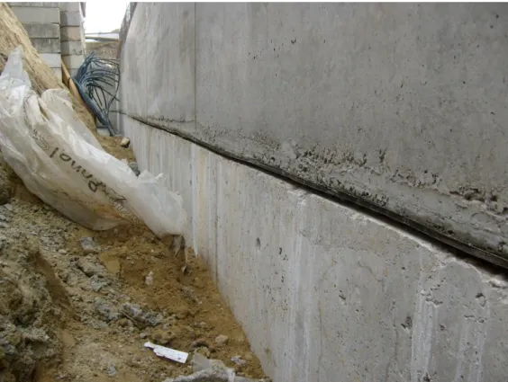
The profiled Cibatur mat, shown in Fig. 19, consists of a fabric reinforced elastomeric plate (sandwich method) that has underneath truncated cone shape spring elements. The surface of the top layer is not only insensitive to weather but also resistant to abrasion, oil and ozone. Natural rubber of high quality is used for the spring elements which have excellent dynamic properties. As presented in Fig. 22, this mat is placed between concrete lawyers. For the project showed in Fig. 21and Fig. 22, the concrete layers are 1.0m thick.
Fig. 19 – Countermeasure (Cibatur) applied in the foundations
To model this countermeasure should be taken into account the building weight, the natural frequency of building and the excitation frequency. In Fig. 20 is represented the insulation effect produced by this product. It is possible to conclude that for high excitation frequencies Cibatur reveals to be very effective. However for lower vibration frequencies this countermeasure has negative effects amplifying the vibration on the structure. This aspect isn’t presented in the following figure because of marketing.
Fig. 21 – Application of bedding elastic for buildings (iC – Consulenten)
3
DYNAMIC ANALYSIS
3.1. INTRODUCTION
The analysis of ground-borne vibrations due to train traffic can be studied idealizing the train as a moving load or a set of moving loads on the surface as well as in the tunnel situation. Its amplitude corresponds to the weight transmitted by the wheels (wheels force) of the train to the track and its frequency corresponds to the time between loads (wheels). Additionally there are a lot of other loads caused by wheel-rail contact and discontinuities along the trackway.
Another aspect that should be taken into account about this issue has to do with the dynamic and quasi-static components of the loads. For large distances the dynamic component of the loads grows importance, the quasi-static component is important for analysis at small distances.
This chapter deals with some important basics on “Dynamic Analysis” concerning some relevant expressions developed for a single-degree-of-freedom (SDOF), and fundamentals of dynamics which are important for ground-borne vibration due to train traffic. However, the complete development of these expressions can be found in books as in “Dynamics of Structures” from Anil K. Chopra or “Vibration, Fundamentals and Practice” from de Silva.
3.2. DYNAMIC MATERIAL MODEL
The dynamic material models should represent the behavior of the soil under dynamic excitation. For this thesis a linear elastic behavior of the soil and its material is considered. The linear elastic model represents the simplest type of stress-strain-time relationship applied, where the stress-strain relation is considered to be approximately linear proportional.
It is the shear strain experimented for the soil that will determine the mathematical models developed to describe the dynamic response of the soil. Usually, the shear strain exhibit in the propagation path due to the vibrations caused by train traffic is below . At this level of shear strain, the behavior of the soil can be characterized through a linear elastic model to describe the dynamic response.
If larger deformations between and as it happens to soil under seismic activity, the soil will show an elasto-plastic behavior, i.e. irrecoverable deformations. To describe this soil response the equivalent material model is more appropriate [2]. However, its application in this issue is not appropriated since the vibration due to train traffic that does not cause significant changes in the shear modulus of the soil. Its application can be found in the study of rubber-modified asphalt concrete as a ballast material [3]; or in the study of the ground vibration under the railway, where the soil can
experiment high deformations. Wherein, the linear hysteretic damping (damping type independent of the frequency) is used to capture the dissipating mechanism of each material.
3.3. EQUATION OF MOTION
The equation of motion aims to represent the coordinates of the mass , at any instant , for each degree-of-freedom of the system. The minimum number of independent coordinates required to determine completely the positions of all parts of a system at any instant of time defines the degree of freedom of the system. The single degree-of-freedom (SDOF) system represents the simplest model which can be idealized to study the motion of an inertia body. The forces acting in the direction of the degree-of-freedom are the applied load ( ), and three resisting forces resulting from the motion, i.e, the inertial force ( ), the damping force ( ), and the spring force ( ).
Fig. 23 – Single-degree-of-freedom system
In Fig. 23 a schematically body is represented with lumped mass, m, excited by the applied load f(t), with the resisting forces represented by a spring with elastic constant k and a viscous damper with a viscous damping ratio cv.
The equation of motion will represent the dynamic equilibrium between these forces,
( ) ( ) ( ) ( ) ( )
where, ( ), ( ) and ( ) represent inertial, damping and elastic force respectively; and ( ) represents the excitation force.
Each of the forces represented in the left hand side of this equation are function of the displacement ( ) or one of its derivatives (velocity and acceleration). In accordance with D’Alembert principle, the inertial force, as it is shown in Fig. 23, is the product of the mass and acceleration,
( ) ̈( ) ( )
̈( ) ( )
![Fig. 2 – Distinctive stages of the study of train-induced ground vibration [1]](https://thumb-eu.123doks.com/thumbv2/123dok_br/15451420.1027658/29.892.299.620.920.1107/fig-distinctive-stages-study-train-induced-ground-vibration.webp)
![Fig. 4 – a) Train transmission system [1]; b) Wheel forces [1]](https://thumb-eu.123doks.com/thumbv2/123dok_br/15451420.1027658/31.892.142.802.215.434/fig-train-transmission-b-wheel-forces.webp)
![Fig. 11 – Response to residential building vibration 4 to 15 rapid transit trains per hour [4]](https://thumb-eu.123doks.com/thumbv2/123dok_br/15451420.1027658/37.892.282.657.209.434/fig-response-residential-building-vibration-rapid-transit-trains.webp)
![Fig. 18 – Building elastically supported [10]](https://thumb-eu.123doks.com/thumbv2/123dok_br/15451420.1027658/45.892.251.680.824.1092/fig-building-elastically-supported.webp)