Cristina Isabel
Fernandes Ferreira
SEPARAÇÃO DE CO
2/CH
4COM LÍQUIDOS IÓNICOS
Ano 2010
Cristina Isabel
Fernandes Ferreira
SEPARAÇÃO DE CO
2/CH
4COM LÍQUIDOS IÓNICOS
CO
2/CH
4SEPARATION WITH IONIC LIQUIDS
Dissertação apresentada à Universidade de Aveiro para cumprimento dos requisitos necessários à obtenção do grau de Mestre em Engenharia Química, realizada sob a orientação científica do Dr. João Araújo Pereira Coutinho, Professor Associado com Agregação do Departamento de Química da Universidade de Aveiro.
o júri
presidente Prof. Dr. Dmitry Victorovitch Evtyugin
Professor associado com agregação do Departamento de Química da Universidade de Aveiro
Prof. Dr. João Araújo Pereira Coutinho
Professor Associado com Agregação do Departamento de Química da Universidade de Aveiro
Doutor José Manuel da Silva Simões Esperança
Investigador Auxiliar no Instituto de Tecnologia Química e Biológica, ITQB2, Universidade Nova de Lisboa
Doutora Mara Guadalupe Freire Martins
Estagiária de Pós-Doutoramento no Instituto de Tecnologia Química e Biológica, ITQB2, Universidade Nova de Lisboa
agradecimentos Após um longo ano encontra-se o trabalho concluído, e no final, olhando para trás, lembramo-nos daqueles que nos ajudaram a conquistar esta vitória, este trabalho que no fundo representa uma conquista de cinco anos.
Em primeiro lugar, agradeço ao meu orientador Professor Doutor João Araújo Pereira Coutinho pela disponibilidade que sempre mostrou, por simplificar o que por vezes parecia complicado de alcançar, e acima de tudo pelo acompanhamento ao longo deste ano.
Agradeço -te Pedro pela simpatia e simplicidade com que me acolheste desde o primeiro dia. A ajuda que me deste foi muito importante, sempre soube que a qualquer dúvida que tivesse podia contar contigo.
Este ano conheci também este grupo a quem tenho agradecer pelo acolhimento, e apesar de não ter estado muito presente, tenho de dar os parabéns a todos os Path pelo companheirismo e entre ajuda que há entre vocês.
A nível pessoal, apesar de não terem interferido directamente na construção deste trabalho, são muitos aqueles a quem devo um muito Obrigada! A ti, Luísa, agradeço pelas longos caminhadas ao fim do dia que apesar de exaustivas, sempre foram uma boa forma de descontrair e ganhar novas forças para continuar o trabalho. Agradeço a compreensão das vezes em que tiveste de trabalhar a dobrar por mim, espero que te tenha compensado noutras ocasiões.
Aos meus Pais, por sempre terem depositado um grande voto de confiança no meu trabalho e acima de tudo, pelos sacrifícios que passaram. Que a
conclusão deste trabalho seja também uma vitória para eles, a prova de que o seu esforço foi compensado.
Por último agradeço-te a ti João, pelos fins de semana bem passados, pela quebra da rotina e pelos momentos de descontracção que foram apoio emocional essencial para o resto da semana. Foi contigo que desabafei as minhas preocupações e inseguranças, foste tu que sempre acreditaste em mim e me deste força.
palavras-chave Dióxido de carbono, metano, líquidos iónicos, separação de CO2/CH4,
solubilidade, interacções, compostos não-voláteis, desvios à idealidade,selectividade CO2/CH4, volume molar, tensão superficial
resumo
As alterações climáticas e as demais mudanças associadas aos gases de efeito de estufa, concretamente ao dióxido de carbono, têm vindo a suscitar cada vez mais interesse, proporcionando a descoberta e o desenvolvimento de técnicas e processos que promovam a mitigação deste gás na atmosfera. Os líquidos iónicos são uma classe de compostos que têm vindo a gerar um interesse crescente, desde a sua descoberta em 1914 até a actualidade. São sais, compostos por iões, líquidos à temperatura ambiente, e possuindo propriedades como baixa pressão de vapor, não inflamabilidade, larga janela eletroquímica, grande estabilidade química e térmica e o facto de serem líquidos numa faixa de temperatura extensa, têm contribuindo para o
desenvolvimento de processos ambientalmente mais conscientes. A troca do catião ou do anião permite alterar significativamente as propriedades do líquido iónico e adaptá-lo ao fim pretendido.
As áreas de aplicação dos LIs têm vindo a expandir, destacando-se neste trabalho a sua aplicação na purificação de correntes de misturas gasosas. A separação do dióxido de carbono de metano é de elevada relevância no que toca à purificação do gás natural. A presença de CO2 diminui o poder de
combustão do gás natural, provoca problemas de corrosão nas tubagens e equipamentos e aquando a combustão do gás natural o CO2 é emitido
contribuindo para a poluição atmosférica.
Neste trabalho utilizaram-se dados de equilíbrio líquido vapor para sistemas de CO2 com líquidos iónicos e outros solventes não voláteis, analisando os
desvios à idealidade apresentados por estes sistemas, tentando perceber desta forma, melhor o mecanismo que controla a solubilidade deste gás. Foram igualmente analisados os desvios à idealidade para sistemas de CH4 e
líquidos iónicos.
Estudou-se para diferentes LIs qual o composto preferencialmente absorvido, CO2 ou CH4, recorrendo ao cálculo da selectividade.
Com o objectivo de analisar como algumas propriedades termodinâmicas dos líquidos iónicos afectam a solubilidade dos gases, estudou-se o efeito do volume molar e da tensão superficial destes solventes.
keywords Carbon dioxide, methane, ionic liquids, CO2/CH4 separation, solubility,
interactions, non volatile compounds, deviations to ideality, CO2/CH4 selectivity,
molar volume, surface tension.
abstract Climate change and other changes related to greenhouse gases, specifically carbon dioxide, have been raising increasing concern, providing the discovery and development of techniques and processes that promote the mitigation of this gas in the atmosphere.
Ionic liquids are a class of compounds that have been generating increasing interest since its discovery in 1914 until today. They are salts, composed of ions, that are liquid at room temperature, and having properties such as low vapor pressure, wide temperature ranges in the liquid state, non-flammability, wide electrochemical window, high chemical and thermal stability, have contributed to the development of more environmentally conscious processes. The exchange of the cation or anion can significantly change the properties of the ionic liquid and adapt it to a specific end in mind.
Ionic liquids application areas have been expanding, focusing this work on its application in the purification of gas streams. The separation of carbon dioxide from methane is very important in the purification process of natural gas. The presence of CO2 reduces the heating value of natural gas, causes corrosion
problems in pipes and equipment and is emited as an atmospheric poluent during natural gas combustion.
In this work we used liquid vapor equilibrium data for CO2 systems with ionic
liquids and other non-volatile solvents, analyzing the non-ideality of these systems, thus trying to understand better the mechanism that controls the solubility of this gas. The non-ideality for systems of CH4 and ionic liquids was
also analyzed.
The prefered sorption of CH4 and CO2 in different ionic liquids was studied,
using the definition of solubility selectivity.
In order to analyze how thermodynamic properties of ionic liquids influence the solubility of these gases, the effect of molar volume and surface tension of these solvents was analyzed.
Contents
Contents ... I List of Figures ... III List of Tables ... VI Nomenclature ...VII List of Symbols ...VII Abreviations ... VIII 1. Introduction ... 1 1.1. Environmental issues ... 2 1.2. Carbon dioxide ... 3 1.3. CO2 Capture Technologies ... 4 1.3.1. Post-Combustion Capture ... 4 1.3.2. Pre-Combustion Capture ... 5 1.3.3. Oxy-Combustion Capture ... 6
1.4. Purification of gas streams ... 6
1.5. Gas treating technologies ... 8
1.5.1. Membranes ... 8 1.5.2. Adsorption... 9 1.5.3. Cryogenic ... 9 1.5.4. Absorption ... 10 1.6. Ionic liquids... 11 1.6.1. IL Properties ... 12 1.6.2. IL Applications... 15
2. Results and Discussion ... 17
2.2. Deviations to ideality of CH4 solubility in ILs ... 34
2.3. CO2 and CH4 solubility dependence with temperature ... 37
2.4. Correlation of CO2 and CH4 solubility in ILs with the surface tension ... 39
2.5. Correlation of CO2 and CH4 solubility in ILs with molar volume ... 43
2.6. CO2/CH4 selectivity ... 48
2.7. Selectivity dependence with IL molar volume ... 50
2.8. Deviations to ideality of CO2/protic IL systems ... 51
3. Conclusions ... 52
List
of
Figures
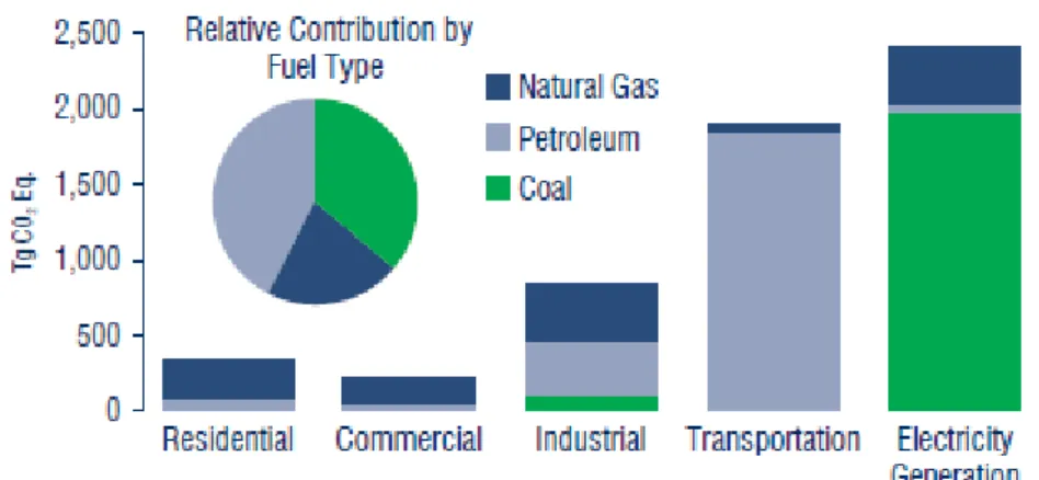
Figure 1.2.1: CO2 emissions from fossil fuel combustion, by fuel type and end-use
sector.[3] ... 3
Figure 1.3.1: Block diagram of Post-Combustion Capture system.[9] ... 4
Figure 1.3.2: Block diagram of Pre-Combustion Capture system.[9] ... 5
Figure 1.3.3: Block diagram of Oxy-Combustion Capture system. [9] ... 6
Figure 1.5.1: Technology options for CO2 Separation and Capture. [17] ... 8
Figure 1.6.1: Evolution of IL generations.[25] ... 11
Figure 1.6.2: Representative cations and anions used as building blocks in IL formulation. [30]... 12
Figure 2.1.1: Literature CO2 solubility data in alkanes + Ideality described by Raoult´s law at ≈313 K. [58-62] ... 21
Figure 2.1.2: Literature CO2 solubility data in alcohols + Ideality described by Raoult´s law at ≈313 K. [63-64] ... 22
Figure 2.1.3: Literature CO2 solubility data in PEGs + Ideality described by Raoult´s law at ≈313 K. [66] ... 23
Figure 2.1.4: Literature CO2 solubility data in fatty acids + Ideality described by Raoult´s law at ≈313 K. [68-69] ... 24
Figure 2.1.5: Literature CO2 solubility data in fatty acid esters + Ideality described by Raoult´s law at ≈313 K. [71-75] ... 25
Figure 2.1.6: Literature CO2 solubility data in Ionic liquids + Ideality described by Raoult´s law at ≈298 K. [41-43, 46-47] ... 26
Figure 2.1.7: Schema of the lattice model for a selected ionic liquid: solid-like structure. [76] ... 27
Figure 2.1.8: Literature CO2 solubility data in alkanes + Ideality described by Raoult´s law and Flory Huggins prediction at ≈313 K. ... 28
Figure 2.1.9: Literature CO2 solubility data in alcohols + Ideality described by Raoult´s
law and Flory-Huggins prediction at ≈313 K. ... 29 Figure 2.1.10: Literature CO2 solubility data in PEGs + Ideality described by Raoult´s
law and Flory Huggins prediction at ≈313 K. ... 30 Figure 2.1.11: Literature CO2 solubility data in fatty acids + Ideality described by
Raoult´s law and Flory Huggins prediction at ≈313 K. ... 31 Figure 2.1.12: Literature CO2 solubility data in fatty acid esters + Ideality described by
Raoult´s law and Flory Huggins at ≈313 K. ... 32 Figure 2.1.13: Literature CO2 solubility data in Ionic Liquids + Ideality described by
Raoult´s law and Flory-Huggins prediction at ≈298 K. ... 33 Figure 2.2.1: Pressure-CH4 molar composition diagram for the systems CH4 + ionic
liquids at ≈313 K.[40, 45-46, 50-51, 53] ... 35
Figure 2.2.2: Pressure- CH4 molar composition diagram for the systems CH4 + ionic
liquids at ≈333,15K.[45, 50-53]... 36
Figure 2.3.1: Solubility of CO2 in [C4mim][CH3SO4] at various temperatures.[77] ... 37
Figure 2.3.2: Solubility of CH4 in [C4mim][CH3SO4] at various temperatures.[53] ... 37
Figure 2.4.1: Logarithm of the Ostwald coefficient for argon as a function of the surface tension of diverse solvents. [80] ... 39
Figure 2.4.2: Henry’s law constants in terms of CH4 solubility as a function of ionic
liquid surface tension at 303K. [41, 45, 81-86] ... 40
Figure 2.4.3: Henry’s law constants in terms of CO2 solubility as a function of ionic
liquid surface tension at 313K.[41, 45, 50, 81-90] ... 41
Figure 2.4.4: Henry’s law constants in terms of CH4 solubility as a function of ionic
liquid surface tension at 313K. [40, 48, 50-51, 82, 87] ... 41
Figure 2.4.5: Henry’s law constants in terms of CH4 solubility as a function of ionic
liquid surface tension at 333 K.[50-53, 82, 87, 89, 91] ... 42
Figure 2.5.1: Henry’s law constants, based on CO2 gas solubility, dependence with
Figure 2.5.2: Henry’s law constants, based on CH4 gas solubility, dependence with
ionic liquid molar volume at 303 K.[40, 48, 50-51, 93] ... 44
Figure 2.5.3: Molar volume-molar mass diagram of ionic liquids. ... 45 Figure 2.5.4: Pressure-molality diagram of CO2 + non volatile solvents at 313 K . [97] 46
Figure 2.5.5: Relation between the solubility determined by equation 13 and the one predicted by Carvalho et al. [97] ... 46
Figure 2.5.6 : Pressure-molality diagram of CH4 + Ionic liquids at 313 K.[40, 51, 53, 98] ... 47
Figure 2.6.1: Solubility selectivity given in terms of Henry’s law constants for CO2/CH4. [40, 45, 48-50, 52-53, 77, 86] ... 48
Figure 2.7.1: Diagram of CO2/CH4 Solubility selectivity as a function of IL molar
volume ... 50 Figure 2.8.1: Literature CO2 solubility data in protic ionic liquids + Ideality described
List of Tables
Table 1.6.1: Examples of areas of application of ionic liquids.[39] ... 15
Table 2.1: Literature solubility data for different systems of CO2 + ILs; Temperature
and pressure ranges. ... 18 Table 2.1.1: Gas Solubility data for the CO2 + alkanes systems; Literature reference. 21
Table 2.1.2: Gas Solubility data for the CO2 + alcohols systems; Literature reference. 22
Table 2.1.3: Gas Solubility data for the systems CO2 + PEGs; Literature reference. ... 23
Table 2.1.4: Gas Solubility data for the systems CO2 + fatty acids; Literature reference.
... 23 Table 2.1.5: Gas Solubility data for the systems CO2 + fatty acid esters; Literature
Nomenclature
List of Symbols
yCO2 Vapor mole fraction of CO2
xCO2
pσ CO2
Liquid mole fraction of CO2
Vapor pressure of CO2
p Total Pressure
GE Excess Gibbs Energy
GE,Res Residual contribution to excess Gibbs Energy
GE,Comb Combinatorial contribution to excess Gibbs energy
R Ideal gas constant
T Temperature
γi Activity coefficient of component i
γiComb Combinatorial term of the activity coefficient of component i
γiRes Residual term of the activity coefficient of component i
φCO2 CO2 volume fraction
VCO2 Volume of CO2
xsolvente Liquid mole fraction of the solvent
Vsolvente Volume of the solvent
H1(T,P) Henry’s Constant
f1L Fugacity of the gas dissolved in the liquid phase
x1 Mole fraction of the gas dissolved in te liquid phase
p1 Partial pressure of the gas
S Solubility selectivity
HCH4 Henry’s law constant of methane
HCO2 Henry’s law constant of carbon dioxide
γ Surface tension
Abreviations
GHGs Greenhouse gases
CCS Carbon capture and storage
PSA Pressure Swing Adsorption
TSA Thermal Swing Adsorption
MEA Monoethanolamine
DEA Diethanolamine
MDEA Methyldiethanolamine
SLM Suported liquid membrane
ILs Ionic Liquids
RTILs Room Temperature Ionic Liquids
VOCs Volatile organic compounds
EDA Electron donor acceptor
VLE Vapour-Liquid Equilibrium
PILs Protic Ionic Liquids
[C2mim][Tf2N] 1-ethyl-3-methylimidazolium bis(trifluoromethylsulfonyl)imide [C4mim][Tf2N] 1-butyl-3-methylimidazolium bis(trifluoromethylsulfonyl)imide [C5mim][Tf2N] 1-methyl-3-pentylimidazolium bis(trifluoromethylsulfonyl)imide [C6mim][Tf2N] 1-hexyl-3-methylimidazolium bis(trifluoromethylsulfonyl)imide
[C4mim][BF4] 1-butyl-3-methylimidazolium tetrafluoroborate [C8mim][BF4] 1-octyl-3-methylimidazolium tetrafluoroborate [C2mim][BF4] 1-ethyl-3-methylimidazolium tetrafluoroborate [C2mim][PF6] 1-ethyl-3-methylimidazolium hexafluorophosphate [C4mim][PF6] 1-butyl-3-methylimidazolium hexafluorophosphate [C6mim][PF6] 1-hexyl-3-methylimidazolium hexafluorophosphate [C4mim][TFA] 1-butyl-3-methylimidazolium trifluoroacetate [C4mim][DCA] 1-butyl-3-methylimidazolium dicyanamide
[C2mim][DCA] 1-ethyl-3-methylimidazolium dicyanamide [C2mim][EtSO4] 1-ethyl-3-methylimidazolium ethylsulfate [C6mpy][Tf2N] 1-hexyl-3-methylpyridinium
bis(trifluoromethylsulfonyl)imide
[C1mim][CH3SO4] 1-methyl-3-methylimidazolium methylsulfate [C4mim][CH3SO4] 1-butyl-3-methylimidazolium methylsulfate [C4mim][Ac] 1-butyl-3-methylimidazolium acetate [C4mim][SCN] 1-n-butyl-3-methylimidazolium thiocyanate
[C2mim][CF3SO3] 1-ethyl-3-methylimidazolium trifluoromethansulfonate [Hemim] [PF6] 1-(2-hydroxyethyl)-3-methylimidazolium hexafluorophosphate [Hemim][OTf] 1-(2-hydroxyethyl)-3-methylimidazolium trifluoromethanesulfonate [Hemim][Tf2N] 1-(2-hydroxyethyl)-3-methylimidazoliumbis-(trifluoromethyl)sulfonylimide [P(14)666][Cl] Trihexyl(tetradecyl)phosphonium chloride [P(14)666][DCA ] trihexyl(tetradecyl)phosphonium dicyanamide [P(14)666][Tf2N] trihexyl(tetradecyl)phosphonium
bis(trifluoromethylsulfonyl)imide
[P(14)444][DBS] tributyl(tetradecyl)phosphonium dodecylbenzenesulfonate
[HEAI] 2-Hydroxyethylammonium acetate
[HEL] 2-Hydroxyethylammonium lactate
[HEF] 2-Hydroxyethylammonium formate
[BHEEA] Bis(2-hydroxyethyl)ammonium acetate
[HHEMEA] 2-Hydroxy-N-(2-hydroxyethyl)-N-methylethanammonium acetate
[BHEAL] Bis(2-hydroxyethyl)ammonium lactate
[HHEMEL] 2-Hydroxy-N-(2-hydroxyethyl)-N-methylethanammonium lactate
[THEEA] Tri-(2-hydroxyethyl)ammonium acetate
[HEAF] 2-(2-Hydroxyethoxy)ammonium formate
[HEAA] 2-(2-Hydroxyethoxy)ammonium acetate
[HCC-C5mim] [Tf2N] 1-Propargyl-3-methylimidazolium bis((trifluoromethyl)sulfonyl)imid [NC-C5mim] [Tf2N] 1-Hexanenitrile-3-methylimidazolium bis((trifluoromethyl)sulfonyl)imide [NC-C3mim] [Tf2N] 1-Butanenitrile-3-methylimidazolium bis((trifluoromethyl)sulfonyl)imide [NC-C2mim] [Tf2N] 1-Ethanenitrile-3-methylimidazolium bis((trifluoromethyl)sulfonyl)imide
1.1. Environmental issues
One of the most prominent global issues of this century is clean energy production. This generalized concern leads to social, economic, and scientific debates that focus on energy usage, energy sources, and sustainable energy strategies.[1]
Climate change is already happening, and represents one of the greatest threats facing our planet. Global average air and ocean temperatures increasing, more frequent extremes of weather, melting glaciers and polar ice, and rising sea levels are some observations that show the warming of the climate.
In the longer term, these changes threaten to cause serious damage to our economies and the environment we depend on, putting the lives of millions of people in danger and causing the extinction of animal and plant species.
These changes are sometimes caused by natural factors but the climate changes that we are witnessing and experiencing today are almost entirely caused by human activities that change the atmosphere's composition.
This mankind activities with impact on the atmosphere began with the Industrial Era, and since then lead to an increasing atmospheric concentration of several greenhouse gases (GHGs), gases that are transparent to incoming solar radiation, but that absorb and reradiate infrared radiation from the Earth, which keeps more heat in our atmosphere, facilitating global warming. [2]
Some greenhouse gases occur naturally and are emitted to the atmosphere through natural processes. During the past century humans have substantially added to the amount of greenhouse gases in the atmosphere by burning fossil fuels such as coal, natural gas, oil and gasoline to power our cars, factories, and by the destruction of forests.
The principal greenhouse gases that enter the atmosphere because of human activities are: CO2, CH4, N2O and fluorinated gases.[3] Of these gases, CO2 is the most
important, accounting for about 80 % of the enhanced global warming effect, even though it has the lowest Global Warming Potential and a relatively short life-time in the atmosphere. [4]
1.2. Carbon dioxide
Carbon dioxide (CO2) is released in a number of ways, naturally during the
carbon cycle and by anthropogenic activities.
Within the carbon cycle occur natural processes that release CO2 into the
atmosphere and that remove CO2 from the atmosphere. Examples of such processes
are animal respiration, by which oxygen and nutrients are converted into CO2 and
energy, and plant photosynthesis by which CO2 is removed from the atmosphere and
stored as carbon in plant biomass.
When in balance, the total carbon dioxide emissions and removals from the entire carbon cycle are roughly equal. In that way, such processes, except when directly or indirectly perturbed out of equilibrium by anthropogenic activities, generally do not change the average atmospheric greenhouse gas concentrations.
Anthropogenic activities, however, can cause additional quantities of these and other greenhouse gases to be emitted or sequestered, thereby changing their global average atmospheric concentrations.
The global largest source of CO2 emissions globally is the combustion of fossil
fuels. When they are burned the carbon stored in them is released almost entirely as CO2. The main fossil fuels burned by humans are petroleum (oil), natural gas and coal,
for electricity generation, industrial uses, transportation, as well as in homes and commercial buildings. Figure 1.2.1 displays emissions for each of these sectors, by fuel type. Petroleum supplies the largest share Coal and natural gas follow in order of importance.
Anthropogenic climate change needs to be addressed, and in that context, measured to avoid inordinate CO2 emissions and energy usage, as well as developing
new energy sources feasible of partially shift the actual fossil fuels energy sources to renewable sources.[5]
The increase of the atmospheric CO2 concentration, however, shows that
strategies to prevent CO2 emission alone will not suffice to stop climate change. In this
context there is a need to develop techniques aiming at the sequestration of CO2,
namely technologies of carbon capture and storage (CCS).[6]
Using these technologies, CO2 could be captured from large, stationary sources,
like power plant flue gases, preventing its release to the atmosphere. Following capture, the CO2 must be compressed and transported to a location, typically in
appropriate geologic formations, for storage.[7-8]
1.3. CO
2Capture Technologies
One very promising approach for reducing CO2 emissions is itscapture at a
power plant, transport to an injection site, and sequestration for long-term storage in any of a variety of suitable geologic formations.[9]
The purpose of CO2capture is to remove carbon dioxide from industrial and
energy-related sources, producing a concentrated stream of CO2 at high pressure
ready for storage.[9]
There are three technological pathways that can be pursued for CO2 capture:
post-combustion capture, pre-combustion capture and oxy-combustion.
1.3.1. Post-Combustion Capture
In post-combustion capture, the CO2is separated from the flue gas produced by
fuel combustion.[9]
Commercially available technologies include CO2 capture using absorption in
an aqueous amine solution. The CO2 is then stripped from the amine solution and
dried, compressed and transported to the storage site.[4]
Some of the options for this type of capture are based on separation principles such as chemical and physical absorption, adsorption, cryogenics and membranes.
1.3.2. Pre-Combustion Capture
Figure 1.3.2: Block diagram of Pre-Combustion Capture system.[9]
In pre-combustion capture, carbon is removed from the fuel before combustion.[4, 9]
For coal this can be done by gasification. After reforming, the product gas is then shifted to produce a hydrogen-rich fuel gas mixed with CO2. The CO2 is removed
by physical absorption and the hydrogen combusted in a gas turbine. In this way the CO2 is removed at a higher concentration in the gas stream and at high pressure.
When applied to natural gas, the gasification step is replaced with a reforming stage to produce the synthesis gas.[4]
1.3.3. Oxy-Combustion Capture
Figure 1.3.3: Block diagram of Oxy-Combustion Capture system.[9]
In oxy-combustion, the fuel is burned in an atmosphere of oxygen that contains little or no nitrogen.[4, 9] This gives a flue gas consisting mainly of CO2 and water vapor
which can be condensed to give a highly concentrated CO2 stream for transport and
storage.
In the case of natural gas, a commonly specified gas turbine combined cycle power plant generates a low CO2 concentration in the flue gas.[4]
Once the CO2 has been separated by any one of the methods identified above,
then it must be compressed into liquid, transported via pipeline, and injected into deep wells for long-term storage or used beneficially for other purposes.
1.4. Purification of gas streams
The separation of CO2 from CH4 is an important process in many industrial
areas such as natural gas processing, biogas purification, enhanced oil recovery and flue gas treatment.[10]
The progress of the international energy demand shows a 1.7% average annual growth in the 2005–2020 period. The worldwide demand for the use of natural gas as a cleaner and more efficient fuel is constantly rising. Novel transport technologies, the remarkable reserves found, the lower overall costs and the environmental sustainability all point to natural gas, less polluting than oil and coal
and now used in more efficient plants, as the primary energy source in the near future.[11]
Natural Gas demand will account for the highest growth rate, and in the future it will exceed that of coal that will be penalized by the increasing restrictions in pollutant emissions.[11]
In addition, natural gas, namely methane, is considered as a main feedstock for the chemical industry.[12]
Although methane constitutes the key component of natural gas, as produced from gas fields, natural gas generally contains considerable amounts of impurities including water, carbon dioxide, nitrogen, sulphur compounds and other hydrocarbons.[11-12]
The carbon dioxide content in natural gas can vary from 4 to 50%. Before a natural gas rich in carbon dioxide can be transported in pipelines to end users, it must be treated to maintain the pipeline quality, this is, to an acceptable level by the gas producer prior to export (2–5% CO2).[13-14]
The reasons why CO2 in natural gas must be reduced to the levels mentioned
above are several. Carbon dioxide reduces the heating value, takes up volume in the pipeline and as an acidic gas, has the potential to cause corrosion in pipes and process equipment. Besides, being a greenhouse gas, the emission of CO2 from the combustion
of the natural gas is a serious concern associated with global climate change, so it has to be removed to prevent atmospheric pollution.[10, 12, 15-16] It is also removed because
it causes catalyst poisoning in ammonia synthesis,[14-15] and is able to solidify in
cryogenic process.[10]
There are many technologies available for treating gas streams as will be shown below.
1.5. Gas treating technologies
There are a wide range of gas purification technologies. Absorption in basic solvents, adsorption and membrane technology are some examples of them as shown in Figure 1.5.1, [12] following a brief description of the most applied in industry.
Figure 1.5.1: Technology options for CO2 Separation and Capture.[17]
1.5.1. Membranes
There are many different types of gas separation membranes, including porous inorganic membranes, palladium membranes, polymeric membranes and zeolites.[18]
They selectively transport gases through the membrane based on the interaction with the membrane and the difference in partial pressure of the gases across it.[4]
A range of configurations exists either simply as gas separation devices or incorporating liquid absorption stages. This process has not yet been applied on a large scale and there are challenges related to the composition and temperature of the flue gases.[19]
Membrane separation processes offer many advantages, including a potential for high energy efficiency, ease of scale-up due to modular design, good weight and space efficiency, and great operational flexibility for handling feed streams of varying compositions or flow rates. Membrane processes usually operate at ambient
temperature thereby avoiding the energy losses associated with heat exchange, and are also environmentally safe. [16]
However, membrane processes are subject to limitations when compared with gas absorption processes, CH4 losses could be higher (depending on the gas
selectivity of the membranes) and the scale-up is less economical.[16]
This is a rather new technology much development is required before membranes could be used on a large scale for capture in power stations.[4, 20]
1.5.2. Adsorption
This operation is based on a cyclical process in which the gas mixture flows through a packed bed of solids such as zeolites or activated carbon, in the surface of which the carbon dioxide is adsorbed. The solid is then purified in stages using differences in either pressure (PSA) or temperature (TSA) to remove the carbon dioxide and compress it for storage. [19-20]
PSA and TSA are commercially practiced methods of gas separation and are used to some extent in hydrogen production and in the removal of CO2 from natural
gas.
Adsorption is not yet considered attractive for large-scale separation of CO2
from flue gas because the capacity and CO2 selectivity of available adsorbents is low.
However, it may be successful in combination with another capture technology.[20]
1.5.3. Cryogenic
This type of technique uses low temperatures to cool, condense and purify carbon dioxide from gas streams. Cryogenic separation is widely used commercially for streams that already have high CO2 concentrations (typically >90%) but it is not
used for more dilute CO2 streams.[20]
Cryogenic separation has the advantage that it enables direct production of liquid CO2, which is needed for certain transport options, such as transport by ship.
Cryogenics would normally only be applied to high concentration, high pressure gases, such as in pre-combustion capture processes or oxygen fired combustion.[20]
A major disadvantage of cryogenic separation of CO2 is the amount of energy
is that some components, such as water, have to be removed before the gas stream is cooled, to avoid blockages.[14]
1.5.4. Absorption
A number of gas purification processes using absorption methods exists. These processes are based on either physical dissolution of gases in liquids or on dissolution combined with chemical reaction in the liquid phase.[21]
The most common technology for CO2 removal today is absorption with amine-based absorbents such as monoethanolamine (MEA), diethanolamine (DEA), methyldiethanolamine (MDEA) and the newly developed sterically hindered amines.[4]
The major advantage of the amine treatment is that it is a widely commercialized technology in which the hydrocarbon loss is almost negligible.
Gas absorption processes constitute at present about 70% of the techniques used for treating natural gas.[16]
To meet the specifications mentioned above, the natural gas is most commonly treated with an aqueous alkanolamine solution in absorption columns. While aqueous amine solutions are effective to remove CO2 from natural gas under a variety of conditions, aqueous amine processes often suffer from issues with corrosion, amine degradation, and solvent losses. Furthermore, the use of aqueous amine processes is highly energy intensive, largely as a consequence of the thermodynamic properties of water.[22]
The major drawbacks of the traditional gas absorption separation processes are mainly caused by the nature of the solvent, and the type of interactions given between the solute and the solvent. In an industrial gas absorption process, it is desirable to achieve fast absorption rates and high solute capacities into a solvent that is easily regenerated and which volume make-up is minimized.[23]
Ionic liquids (ILs) seem suitable for being used as a solvent in gas absorption; their potential for replacing the traditional solvents is attributed to their singular characteristics. For example many ILs show a high solubility for carbon dioxide and therefore are promising substances for gas separation processes in which CO2 shall be separated from a mixture. Such type of separation includes the reduction of the CO2
concentration in natural gas, which contains up to 10% CO2, depending on the source area. As essential data, for using ILs in such gas-separation processes, the solubility of methane, as main component of natural gas, carbon dioxide, and their mixtures must be measured.[24]
The potential of ILs for replacing the traditional solvents is attributed to their singular characteristics. The non-volatile nature of ionic liquids plays two important roles. First, there will be no cross-contamination of the gas stream by the solvent during operation, this means no solvent loss and no air pollution. Second, regeneration of the solvent is easy, a simple flash or mild distillation step is all that is required to remove the gas from the solvent, again with no cross-contamination.
In addition to their use as conventional absorbents, ionic liquids may also be immobilized on a support and used in a supported liquid membrane (SLM).
1.6. Ionic liquids
Ionic Liquids have attracted an increasing interest in the last decades with a diversified range of applications. The types of ionic liquid available have also been extended to include new families and generations of ionic liquids with more specific and targeted properties, Figure 1.6.1.
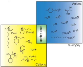
Generally, ILs are salts composed of organic cations and organic or mostly inorganic anions. They have melting points less than 100 °C and many of the most interesting systems actually have melting points around or below room temperature which are called “Room Temperature Ionic Liquids” (RTILs).[26-28] The cation is
generally a bulk organic structure with low symmetry.[29] Common ionic liquids
anions and cations are shown in Figure 1.6.2.
Figure 1.6.2: Representative cations and anions used as building blocks in IL formulation.[30]
However these are only a sample of the almost infinite variety available; the possible choices of cation and anion that will result in the formation of ILs are numerous.
They have many fascinating properties which make them of fundamental interest since both the thermodynamics and kinetics of reactions carried out in ionic liquids are different to those in conventional molecular solvents.[31]
1.6.1. IL Properties
There is a great interest in ILs because of their special properties. As they are made up of at least two components which can be varied (the anion and cation), they can be designed to possess a particular set of properties. [31]
One of the most important characteristics that distinguishes ionic liquids from other salts is the fact that most of them remain liquid at room temperature, since their ions do not pack well and thus reduces the lattice energy.[32-33]
In contrast to traditional organic solvents, these compounds do not evaporate, the coulombic interactions in ILs are in most cases remain strong enough to make the ILs vapor pressure negligible at room temperature. Thus no volatile organic components are created, so they cannot lead to fugitive emissions.[32-34] This makes
ILs a serious alternative for volatile organic compounds which contributes towards a clean and “green” chemistry.[26-27] They minimise the risk of atmospheric
contamination and reduce associated health concerns, that is why they are frequently called ‘‘green solvents’’.[35]
The low vapour pressure makes them combustion resistant, evaporation-proof, and suitable for vacuum applications, and the melting point below the decomposition temperature means that many ILs have very wide temperature ranges in the liquid state.[34]
Their ionic character is mainly responsible for an unusual solubility behavior of substances, which are hardly soluble in normal solvents.[36] They have the ability to
dissolve many different organic, inorganic, organometallic and polymeric materials: high solubility implies smaller reactor volumes.[37]
Other general important properties are: -They are relatively cheap, and easy to prepare.[37]
-They are highly polar. [26]
-They consist of loosely coordinating bulky ions.
-They have high thermal conductivity and a large electrochemical window. -They show good electrical conductivities and moderate viscosities. [36]
-Thermally stable[26-27]
-Nonflammable and not explosive[26-27]
-Less toxic than usual organic solvents
-They are feasible to recycle and repeatedly reuse them.[33]
-They have ionic interactions (mutual electrostatic attraction or repulsion of charged particles), which makes them very miscible with polar substances. At the same time
the presence of the alkyl chain on the cation determines their solubility in less polar fluids.[38]
They exhibit the ability to dissolve a wide variety of compounds like salts, fats, proteins, amino acids, surfactants, sugars and polysaccharides. ILs have very powerful solvent properties allowing them to dissolve a wide range of organic molecules, including crude oil, inks, plastics, and even DNA.[33]
As the chemical structure of ILs is made up of at least two components which can be varied (the anion and cation), the solvents can be designed with a particular end use in mind, or to possess a particular set of properties, that’s the reason, why they are also known as “designer solvents”.[27, 29-31, 38]
Properties such as melting point, viscosity, water-miscibility,[30-31] density,
hydrophobicity,[31] acid/base character, and coordinating ability[30] can be varied by
simple changes to the structure of the ions.[34] The fine tuning of properties is
possible by the variation of the cation or anion family and/or by the length and branching of the alkyl groups incorporated into the cation.[38]
So, as they can be tuned for specific properties, it’s not surprising that this salts show tremendous employments in a variety of chemical processes.
1.6.2. ILApplications
By varying the cations and anions, the physico-chemical properties of ionic liquids can be tuned and specifically optimised for a wide range of applications. Some of them are exemplified in Table 1.6.1.
Table 1.6.1: Examples of areas of application of ionic liquids.[39]
Ionic liquid market segments with examples of possible applications: Engineering Fine Chemistry Energy Storage
• Extraction • Separation • Distillation • Adsorption • Gas storage • Engineering fluids • Membrane technology • Organic synthesis (incl. Peptides & Oligonucleotides) • Inorganic synthesis • Catalysis • Fluorocontaining groups • Enzyme catalysis • Cellulose • Polymers • Petrochemistry • Electrochemical double layer (ECDL) capacitors • Batteries
• Fuel cells • Mobile energy
Surface Technology Electrochemistry
• Surfactants • Lubricants • Antistatic • Anti corrosion • Dispersions • Sensors • Electroplating • Electrochromic devices • Light emitting EC-cells • Dye sensitized solar cell /Photovoltaic
The major application areas of ionic liquids are as solvent replacement, in purification of gases, heterogeneous and homogeneous catalysis and biological reaction media.[33]
1.6.2.1. Solvent replacement
Environmental care and development of cleaner technologies has become a major concern throughout both industry and academia. Thus, the search for alternative solvents has become a high priority. Ionic liquids, known to be environmentally friendly, could easily stand as a viable replacement to the hazardous VOCs in large scale. ILs are able to dissolve a variety of solutes and therefore, be used
in liquid–liquid extractions where hydrophobic molecules will partition to the IL phase.[33]
1.6.2.2. Purification of gases
The use of ionic liquids for gas separation processes has recently attracted much attention due to high solubilities of various gaseous species in ionic liquids.
The non volatility of ILs prevents any cross contamination of the gas stream by the solvent during the process. Moreover, regeneration of the solvent may be easily performed by a simple flash or distillation to remove the gas from the solvent without cross contamination. Moreover, the no solvent loss and no air pollution derived from their non volatility makes ILs as even more attractive replacements.[33, 40]
As already mentioned, ILs can be used as supported liquid membranes. In conventional membranes, gas dissolves in liquid but then the liquid in which the gas dissolved evaporates rendering the membrane useless. Due to the non volatility of ILs, they can be immobilized on a support and used as supported liquid membranes. ILs are also used for storage and delivery of hazardous specialty gases such as phosphine (PH3), arsine (AsH3) and stibine (SbH3).[33]
1.6.2.3. Homogenous and heterogeneous catalysis
Both homogeneous and heterogeneous catalysis have many advantages associated. Combining the advantages of both processes brings considerable process enhancements that can be achieved through the use of ionic liquids.
A selected IL may be immiscible with the reactants and products, but on the other hand may also be able to dissolve the catalysts. ILs combine the advantages of a solid for immobilizing the catalyst, and the advantages of a liquid for allowing the catalyst to move freely. [33]
Some of the examples in chemical reactions and catalysis where ILs are utilized are: reactions of aromatic rings, clean polymerization, Friedel Crafts alkylation, reduction of aromatic rings, carbonylation, halogenation, oxidation, nitration, sulfonation, solvents for transition metal catalysis, immobilization of charged cationic transition metal catalysis in IL phase without need for special ligands, in situ catalysis directly in IL.[33]
The use of ionic liquids as solvents in gas separation processes requires knowledge about the solubility of the main components that constitute the gas stream in study. In this specific case, data of the solubility of methane (CH4) and carbon
dioxide (CO2) is essential, and in that way it was collected from literature. In Table 2.1
are presented the references of all experimental data obtained from literature for different ILs and their pressure and temperature ranges.
Table 2.1: Literature solubility data for different systems of CO2 + ILs and CH4 +ILs;
Temperature and pressure ranges.
Gas Ionic Liquid p/MPa T/K Literature Reference
CO2 [C2mim][Tf2N] 0.6-50 293-363 [41] [C4mim][Tf2N] Up to 15 283-333 [42-43] [C5mim][Tf2N] 0.6-50 293-363 [41] [C6mim][Tf2N] Aprox. 0.1 298-343 [44-45] [C4mim][BF4] Up to 1.3 283-323 [42] [C4mim][PF6] Up to 1.3 283-323 [46] [THTDP][Tf2N] 0.1-72 293-363 [47] [C6mpy][Tf2N] Aprox. 0.1 298-333 [40] [C2mim][BF4] Aprox. 0.1 298-343 [45] [C4mim][CH3SO4] Aprox. 0.1 298-343 [45] [C2mim][CF3SO3] Aprox. 0.1 298-323 [48] [C2mim][DCA] Aprox. 0.1 298-323 [48] [H3C-C5mim][Tf2N] Aprox. 0.1 313 [49] [H3C-C3mim][Tf2N] Aprox. 0.1 313 [49] [H3C-C1mim][Tf2N] Aprox. 0.1 313 [49] [HCC-C5mim][Tf2N] Aprox. 0.1 313 [49] [NC-C5mim][Tf2N] Aprox. 0.1 313 [49] [NC-C3mim][Tf2N] Aprox. 0.1 313 [49] [NC-C2mim][Tf2N] Aprox. 0.1 313 [49] CH4 [C4mim][PF6] Up to 1.3 283-333 [42, 50] [C2mim][BF4] Up to 1.3 283-343 [42, 45, 51] [C6mim][Tf2N] Up to 10 293-413 [45, 52] [C6mpy][Tf2N] Aprox. 0.1 298-333 [40] [C2mim][Tf2N] Aprox. 0.1 298-343 [45] [C4mim][BF4] Aprox. 0.1 283-343 [51] [C4mim][CH3SO4] Up to 10. 293-413 [45] [53] [C2mim][CF3SO3] Aprox. 0.1 313 [48] [C2mim][DCA] Aprox. 0.1 313 [48] [H3C-C5mim][Tf2N] Aprox. 0.1 313 [49] [H3C-C3mim][Tf2N] Aprox. 0.1 313 [49]
[H3C-C1mim][Tf2N] Aprox. 0.1 313 [49] [HCC-C5mim][Tf2N] Aprox. 0.1 313 [49] [NC-C5mim][Tf2N] Aprox. 0.1 313 [49] [NC-C3mim][Tf2N] Aprox. 0.1 313 [49] [NC-C2mim][Tf2N] Aprox. 0.1 313 [49]
2.1. Deviations to ideality of CO
2solutions in non volatile
solvents
The first aim of this work is to develop a deeper understanding of the molecular mechanism that dominates the CO2 sorption. For this purpose, non ideality
of CO2 solubility in ionic liquids and in non-volatile solvents is analyzed, since non
volatile solvents have a low vapor pressure like IL; study them will contribute to understand the CO2 sorption in ionic liquids.
The non ideality of a solution and its impact on the solubility of a given solute depends on the solute-solute, solute-solvent and solvent-solvent interactions. Up to present several authors have discussed the solute-solvent interactions, but this type of interactions alone only allows an understanding of how the solvent molecules surround and interact with the solute ions.
The CO2 molecule is an amphoteric substance that can act as either an acid
(electron donor) or a base (proton acceptor) according to the nature of the solvent molecule, forming electron donor acceptor (EDA) complexes.[54-55]
Some evidences reported by few authors revealed that the strength of the interactions between CO2 and the solvent are not sufficient to explain the solubility of
this molecule. [54-57]
Danten et al. [54] in their paper to a better understanding of interactions of
carbon dioxide (CO2) with organic and/or inorganic compounds, showed that even though the CO2 EDA complexes with sp3 O-donating atoms (such as H2O and alcohols)
are more stable than complexes involving sp2 O-donating atoms (such as aldehydes
and ketones) the solubility data shows that CO2 is less soluble in the former than on
Kazarian et al. [56] observed that the strength of the interactions between
solute and solvent cannot be the only responsible for the solubility of CO2 in ionic
liquids. Their results contradicted those expected by other researchers that also studied systems of CO2 with BF4 and PF6 anions, because they predicted that the
strength of the interaction between CO2 and PF6, in ionic liquids, should be stronger
than with BF4, and this was not consistent with Kazarian’s results that provide strong evidence that what happens is exactly the opposite.[56]
Other researchers that in their work concluded that interactions between the ionic liquids and the dissolved CO2 has no direct relationship on the solubility of CO2
was Seki et al.[57] They showed that although the interactions of CO2 with BF4and PF6
anion-based ILs are stronger than those with the Tf2N, the solubility of CO2 on these
ionic liquids is larger than in the former and thus the interactions alone are not enough to provide an explanation for the CO2 sorption.
The solubility of gases in ionic liquids and other non-volatile solvents still raises some doubts, namely regarding to what are the real properties that affect it. Besides the data presented in Table 2.1 for CO2/ionic liquid systems, to analyze the
non ideality of CO2 in non volatile solvents solutions, experimental VLE data was
collected for systems of CO2 with long chain alcohols, long chain alkanes, fatty acids
and fatty acid esters.
The experimental solubility data of all systems was compared with those on an ideal solution. An ideal solution is one that can be described by Raoult's law that is defined as
(1) where is the vapor pressure and is the liquid and the vapor mole fraction of CO2. As the solvents in question are non-volatile, it can be considered that
the vapor phase is pure CO2, , so that the equation becomes
(2) For each system the results are plotted and presented from Figure 2.1.1 to Figure 2.1.6.
In Table 2.1.1 is reported the solubility data of CO2 in Alkanes found in the
represented in Figure 2.1.1 along with the dashed line given by Raoult´s law that represents an ideal solution.
Table 2.1.1: Gas solubility data for the CO2 + alkanes systems; Literature reference. Gas Non volatile solvent Literature Reference
CO2 Decane [58] Pentadecane [59] Hexadecane [59-60] Nonadecane [58] Eicosane [61-62] Docosane [61]
Figure 2.1.1:Literature CO2 solubility data in alkanes + Ideality described by Raoult´s law at
≈313 K. [58-62]
The representation of the CO2 isothermal solubility data (p-xCO2) of different
alkanes in Figure 2.1.1 shows that the data collected from literature practically overlaps the straight line given by Raoult’s law. This means that this type of systems present a near ideal behavior at low mole fraction compositions of CO2, and that a
CO2-alkane interaction is just like a CO2-CO2 and alkane-alkane interaction.
For the systems in which the solvents are alcohols, the data from literature is shown in Table 2.1.2. The data is plotted at temperatures close to 313 K along with Raoult’s law.
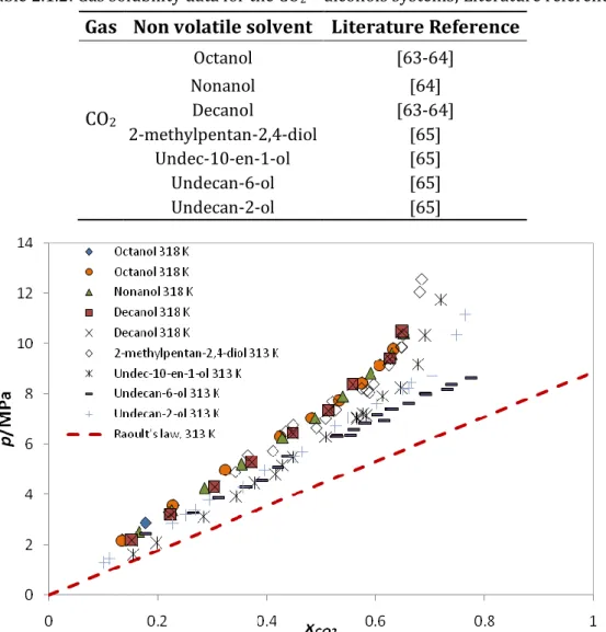
Table 2.1.2: Gas solubility data for the CO2 + alcohols systems; Literature reference. Gas Non volatile solvent Literature Reference
CO2 Octanol [63-64] Nonanol [64] Decanol [63-64] 2-methylpentan-2,4-diol [65] Undec-10-en-1-ol [65] Undecan-6-ol [65] Undecan-2-ol [65]
Figure 2.1.2: Literature CO2 solubility data in alcohols + Ideality described by Raoult´s law at
≈313 K. [63-64]
It can be observed that all the solubility data is placed above the ideality line, so these systems present positive deviations to ideality. This shows that the intermolecular forces between molecules of CO2 and alcohol are less important than
they are between CO2-CO2 and alcohol-alcohol molecules.
The CO2+ PEG systems, unlike those one discussed previously present negative
deviations to ideality that increase with the polymer molecular weight. The behavior of the data found in literature referenced in Table 2.1.3 can be observed in Figure 2.1.3.
Table 2.1.3: Gas solubility data for the systems CO2 + PEGs; Literature reference.
Gas Non volatile solvent Literature Reference
CO2
PEG 400 [66] PEG 600 [66] PEG 1500 [67]
Figure 2.1.3: Literature CO2 solubility data in PEGs + Ideality described by Raoult´s law at
≈313 K. [66]
With respect to the systems whose non volatile solvents are fatty acids, CO2
solubility information is reported in Table 2.1.4. The representation of this data and the ideality described by Raoult´s law can be seen in Figure 2.1.4.
Table 2.1.4: Gas Solubility data for the systems CO2 + fatty acids; Literature reference. Gas Non volatile solvent Literature Reference
CO2
Hexanoic Acid [68] Octanoic Acid [68-69] Decanoic Acid [69] Octadecenoic Acid [70-71]
Figure 2.1.4: Literature CO2 solubility data in fatty acids + Ideality described by Raoult´s law
at ≈313 K. [68-69]
These systems present mild positive deviations that become ideal and then negative as the molecular weight of the acid increases. The negative deviations observed for the large molecular weight compounds, as well as for PEGs, suggests that the solubility is entropically driven.
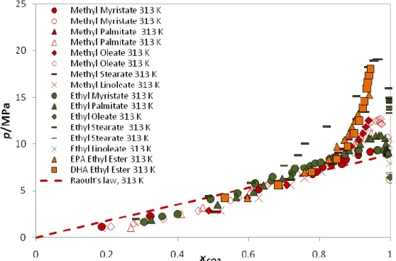
In Table 2.1.5 all the data used for the systems with fatty acid esters is presented. The solubility diagram is plotted at 313 K as can be seen in Figure 2.1.5.
Table 2.1.5: Gas Solubility data for the systems CO2 + fatty acid esters; Literature reference.
Gas Volatile solvent Literature Reference
CO2 Methyl Myristate [71-72] Methyl Palmitate [71-72] Methyl Oleate [73-74] Methyl Stearate [72] Methyl Linoleate [73] Ethyl Myristate [74] Ethyl Palmitate [74] Ethyl Oleate [75] Ethyl Stearate [74-75] Ethyl Linoleate [75] EPA Ethyl Ester [73] DHA Ethyl Ester [73]
Figure 2.1.5: Literature CO2 solubility data in fatty acid esters + Ideality described by Raoult´s
law at ≈313 K. [71-75]
The p-x data lies below the Raoult´s law line on the VLE region, and so these systems are said to have negative deviations from ideality.
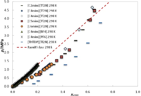
Figure 2.1.6 shows the RTIL CO2 solubilities compared to Raoult’s law. The
deviations from ideality are negative and so, as observed for all systems, except those with alcohols, the CO2 solubility seems to be entropically driven.
Figure 2.1.6: Literature CO2 solubility data in Ionic liquids + Ideality described by Raoult´s law
at ≈298 K. [41-43, 46-47]
A more relevant way to quantify the deviations from ideality of a given mixture is to estimate its excess Gibbs energy. The excess Gibbs energy of a solution may be expressed as the sum of the combinatorial contribution, GE,Comb, and the residual
contribution, GE,Res:
(3) The combinatorial part provides the contribution due to differences in size and
shape of the molecules in the mixture, while the residual part accounts for the interactions between the species. Now it is of interest to analyze the combinatorial part, the entropic effects due to the size and shape, since we have seen that the non ideality does not result only from the intensity of the interactions between the molecules (the residual term).
The vapor pressure of a mixture in a non-ideal case can be described in a similar way as that shown before for an ideal solution trough the use of an activity coefficient, by the so called modified Raoult’s law
The activity coefficient is related to the excess Gibbs energy and can be defined as
(5) The activity coefficient of a component i can be considered as the sum of two contributions, but only the combinatorial part will be hereafter analysed.
(6) The use of lattice models has already been applied by several authors to model ionic liquid by assuming that the fluid structure can be approximated by a solid-like structure as that of Figure 2.1.7. This is possible, because due to some properties of ionic liquids, they seem to share characteristics that makes them somewhat like polymer systems, namely the fact that they are usually composed of cations and anions with long alkyl chains or a long chain like structure and their negligible vapor pressures. [76]
Figure 2.1.7: Schema of the lattice model for a selected ionic liquid: solid-like structure. [76]
In this work, the Flory–Huggins model was used to express the contribution to non-ideality that is caused by the entropic effects, that is given by the activity coefficient expressed as:
ln (7)
where is the volume fraction of CO2 and is given by
(8)
(9)
So, to obtain a prediction of the solubility of CO2 in the different solvents the modified
Raoult´s law was determined and represented for a model system.
For the CO2-alkanes system the result is represented in Figure 2.1.8 along with
the data already presented before.
Figure 2.1.8: Literature CO2 solubility data in alkanes + Ideality described by Raoult´s law and
Flory Huggins prediction at ≈ 313 K.
The Flory-Huggins model predicts a line that lies below the ideal one, so for this case it predicts negative deviations to ideality. As the literature data represented have near ideal behavior, the CO2-alkane interactions must be weaker than the CO2
-CO2 or alkane-alkane interactions so that there is an effect of positive deviations from
the residual part that was not taken into account and that explains this near ideal behavior.
For the CO2-alcohol systems, the deviations to ideality predicted by the
Figure 2.1.9: Literature CO2 solubility data in alcohols + Ideality described by Raoult´s law and Flory-Huggins prediction at ≈ 313 K.
As can be seen, even though the CO2-OH strong interaction the solubility data
lies all above the ideality. In this way, it can be concluded that in spite of being very strong the CO2-OH are not stronger than the OH-OH interactions. This is a good
example that shows that even the solute-solvent interactions are strong it doesn’t mean that we have an enhanced solubility, solubility doesn’t depend only on these interactions.
With regard to the systems with PEGs, the result prediction is shown in Figure 2.1.10. The non-ideal behavior can be well described by the Flory-Huggins equation.
Figure 2.1.10: Literature CO2 solubility data in PEGs + Ideality described by Raoult´s law and
Flory Huggins prediction at ≈ 313 K.
As for the systems with PEGs, also those with fatty acids show a non-ideal behavior than can be described by the Flory-Huggins equation. Such results lead to believe that the deviations are mainly due to the entropic effects, and that the residual contribution has no effect on them and in some cases it can be even negative.
Figure 2.1.11: Literature CO2 solubility data in fatty Acids + Ideality described by Raoult´s law
and Flory Huggins prediction at ≈ 313 K.
When fatty acid esters play the solvent role, the negative deviations by Flory Huggins predictions to the ideal behavior are large, suggesting that the residual contribution for the non ideality is negative. In that way, it seems that the CO2 -carbonyl interactions are energetically favorable when compared with the CO2-CO2
interactions and the carbonyl-carbonyl interactions established between the ester molecules, thus favoring the formation of the Electron Donor-Acceptor complexes formed between CO2 and the carbonyl group of the fatty acid esters. This probably
means that if we add a carbonyl group to the ionic liquid structure, the CO2 solubilty
Figure 2.1.12: Literature CO2 solubility data in fatty acid esters + Ideality described by
Raoult´s law and Flory Huggins at ≈ 313 K.
In the systems of CO2-Ionic liquids, Figure 2.1.13, the solubility data
represented lies between the straight line of Raoult’s law and that predicted by the Flory-Huggins model. Thus, deviations in ionic liquids are intermediate between the ideal behavior and the predicted by the Flory-Huggins model. This type of behavior suggests that the combinatorial term of the Gibbs free energy is larger than the residual, which implies that the solubility of CO2 in ILs is controlled by entropic
effects. But, since the experimental data, obtained from literature, lies somewhat above that predicted by Flory-Huggins, one may implie that there must be some unadjustment in the solute-solvent interactions relatively to the solute-solute and solvent-solvent interactions that are destroyed upon the salvation of the solute and that are not energetically compensated.
Figure 2.1.13: Literature CO2 solubility data in Ionic Liquids + Ideality described by Raoult´s
law and Flory-Huggins prediction at ≈298 K.
From the prediction of the non-ideality results the Flory-Huggins predicts a larger solubility of CO2 in ionic liquids than that is observed experimentally.
For most of the systems studied, the deviations are essentially due to entropic effects, that is, due to the differences in size and shape of the molecules in the mixture. This analysis also supports the idea that the solubility of CO2 is not directly
related to the intensity of the CO2-solvent interaction or in other words, to the
stability of the EDA complex formed. Since the entropic effect increases as the size difference between the CO2 molecule and the solvent increases, increasing the size
2.2. Deviations to ideality of CH
4solubility in ILs
The other component that is of interest to this work is methane, and so, the study of the deviations to ideality for systems of this gas with ILs is important for a better understanding of the CO2/CH4 separation with ionic liquids.
For this, as in the case of CO2, the experimental solubility data in IL was taken
from different sources of the literature and is reported in Table 2.1. The solubility is given in terms of p-xCH4 isotherms data and in some cases in terms of Henry’s law
constants. The solubility of CH4 in ILs is linear with pressure so some authors prefer
to use Henry’s constants to describe their behavior, rather than showing the individual data points.
The solubility of a gas in a liquid is frequently described in terms of Henry’s law, which is defined as
(10)
where H1(T,p) is the Henry’s constant , f1
L
is the fugacity of the gas dissolved in the liquid phase and x1 is the mole fraction of gas dissolved in the liquid phase. The
Henry’s constant depends on temperature but is relatively insensitive to pressure. Knowing that the fugacity of the gas in the liquid phase must be equal to the fugacity of the gas in the gas phase and approximating the gas phase fugacity as the gas phase pressure, the following form of Henry’s law can be obtained
(11) where p1 is the partial pressure of the gas and H1(T) will have units of pressure and is
inversely proportional to the mole fraction of gas in the liquid. Henry’s law predicts a linear relationship between the solubility and the pressure, and only at higher pressures a deviation to this linearity is expected.
All Henry’s law constants are calculated on a mole fraction basis. A large value of the Henry’s law constant corresponds to low solubility, while a small value indicates high gas solubility.
In an ideal solution there is no energy change from mixing the components and no volume change. Each component operates independently so that there are no
synergistic effects of the components being mixed together. In that way, as an example of an ideal solution we have here adopted the behavior of the CH4/n-hexane
solution, as their molecular structures are very similar, when they are mixed, a methane-hexane interaction will be almost like a methane-methane interaction or hexane-hexane interaction. Thus, considering our specific work conditions, for the systems involving methane, the ideality can be assumed as the system CH4/Hexane.
Figure 2.2.1 and Figure 2.2.2 illustrates the p-x diagrams for the different ILs and the ideality given by the p-x data of CH4/hexane system at 311 K and 333 K
respectively.
Figure 2.2.1: Pressure-CH4 molar composition diagram for the systems CH4 + ionic liquids at
Figure 2.2.2: Pressure- CH4 molar composition diagram for the systems CH4 + ionic liquids at
≈333 K.[45, 50-53]
As typically observed for gas solubilities in liquids, the solubility decreases as temperature increases.
On the basis of the diagrams presented, it can be seen that all the solubility data lies well above the ideal line, so these systems have in general strong positive deviations to ideality. Due to these results, it seems correct to say that the CH4-IL
interactions are non favorable and much weaker than the IL-IL ones.
For a given anion, it is observed that the alkyl chain length in the cation and the type of cation influences the solubility of CH4 in ILs. It seems that for a series of
ionic liquids with the same anion, [Tf2N], the solubility increases as the chain length on the imidazolium ring of the cation increases in the order [C2mim] <[C6mim]. The
pyridinium cations present a higher solubility of CH4 relatively to the imidazolium
cations. The solvent effect on chemical processes can be understand in terms of polarity of the solvent, and so as CH4 is a non polar molecule, it will dissolve better in
a solvent of lower polarity. The imidazolium ring has a higher polarity than the pyridinium, and so CH4 is less soluble in the imidazolium ionic liquid as can be seen in
Figure 2.2.1.The greater the polarity of ILs the higher the deviation to ideality in the CH4-IL systems.
The behavior of ionic liquids having the same cation, [C4mim], reveal that the CH4
solubility is very dependent on the anion type. The solubility increases in the order [CH3SO4]<[BF4]<[PF6]<[Tf2N]. For the cation [C2mim] can be observed that the solubility increases in the order [BF4]<[Tf2N].
2.3. CO
2and CH
4solubility dependence with temperature
In Figure 2.3.1 and Figure 2.3.2 isotherms for CO2 and CH4 in
[C4mim][CH3SO4] are presented.
Figure 2.3.1: Solubility of CO2 in [C4mim][CH3SO4] at various temperatures.[77]
In the case of CO2 the solubility seems to be strongly temperature dependent,
since, as can be seen in Figure 2.3.1, the isotherms are well separated. As the temperature increases, the solubility becomes lower.
In the case of CH4 the behavior is different, the isotherms presented practically
overlap each other which shows the low temperature dependence of CH4 solubility.
The solubility remains almost the same for the different temperatures presented. Besides the different influence of temperature upon the gas solubility, the figures reveal a large difference in the solubility of these gases in ionic liquids. It is clearly that CO2 presents a larger solubility than CH4.
![Figure 1.6.1: Evolution of IL generations. [25]](https://thumb-eu.123doks.com/thumbv2/123dok_br/15929063.1094780/28.892.195.719.787.1064/figure-evolution-of-il-generations.webp)