FACULDADE DE ENGENHARIA DA UNIVERSIDADE DO PORTO
Development of a Drop Weight
Machine for Adhesive Joints Testing
Diogo do Paço Casal Antunes
Integrated Master in Mechanical Engineering Specialization in Automation
Supervisor: Prof. António Mendes Lopes Co-Supervisors: Inv. Carlos Moreira da Silva
Prof. Lucas FM da Silva
Development of a Drop Weight Machine for
Adhesive Joints Testing
Diogo do Paço Casal Antunes
Integrated Master in Mechanical Engineering
Specialization in Automation
i
Resumo
Os materiais adesivos estão a ser considerados, cada vez mais, como um dos melhores métodos para unir peças de diferentes características, estando, por isso, a ser muito procurados na indústria automóvel e aeroespacial. Assim, é importante acompanhar este crescente interesse neste tipo de ligações com estudos que as caraterizem devidamente.
Os membros do Grupo de Investigação de Adesivos da FEUP preocupam-se em contribuir para este novo campo de investigação, estudando as propriedades destes materiais e as suas técnicas de adesão. Logo, é importante o grupo possuir o equipamento adequado para o poder fazer. Contudo, apesar de usufruir de vários equipamentos de teste, ainda necessita de um para realizar testes de impacto a baixa velocidade.
Como tal, o principal objetivo desta dissertação é continuar o trabalho feito por quatro ex-alunos de mestrado da FEUP no desenvolvimento de uma máquina de impacto, nomeadamente uma máquina de queda de massas. Esta dissertação inclui o processo de implementação de um sub-sistema anti ressalto e de um novo conjunto bigorna-impactor, dotado de um acelerómetro e de uma célula de carga piezoelétricos. Para além destas novas implementações, houve também a necessidade de ajustes e adições nos circuitos elétrico, pneumático e de comando, assim como o desenvolvimento de uma interface para operar a máquina. Após a máquina estar toda equipada, foram realizados testes que validaram o seu funcionamento.
iii
Abstract
Adhesive materials are increasingly being considered as one of the best methods for joining parts with different characteristics and, therefore, are highly sought out in the automotive and aerospace industries. Thus, it´s important that the growing interest in this type of bonding is supported by studies that correctly characterizes them.
The members of the Adhesives Investigation Group of FEUP are interested in contributing to this field of research by studying these materials´ properties and techniques. So, it´s important they are provided with the adequate equipment to be able to do it. However, despite having several testing machines, they still require one that performs impact tests at low velocities.
As such, the main objective of this dissertation is to continue the work done by four previous master´s students of FEUP in the development of an impact machine, namely a drop weight machine. This dissertation includes the implementation of an anti-rebound sub-system and a new anvil-impactor assembly, equipped with a piezoelectric accelerometer and a piezoelectric load cell. In addition to these new implementations, there was also the need for some adjustments and new components in the electrical, pneumatic and control circuits, as well as the development of an interface to operate the machine. After the machine is completely equipped, impact tests were made to validate it.
v
Acknowledgements
Firstly, I would like to thank to all my family and friends for the support, caring and happiness they constantly give me, which makes me want to continue to construct my character and be the best person I can be.
To my supervisors, Prof. António Mendes Lopes, Inv. Carlos Moreira da Silva and Prof. Lucas da Silva, for all the advices, knowledge and support they gave during this dissertation.
To all ADFEUP´s members for the positive and motivational environment they provided me. In addition, I would like to give special thanks to Eng. Eduardo Marques, Eng. José Machado and Eng. Ricardo Carbas for their great accessibility, help and knowledge.
And finally, to Mr. André Alves, Mr. Domingues Carvalho, Mr. Joaquim Silva, Mr. Pedro Falcão and Mr. António Ramalho for all their time and patience, without whom the work of this dissertation wouldn´t be possible.
vii
Contents
Resumo i Abstract iii Acknowledgements v Acronyms xv 1. Introduction 11.1. Context and Motivation ... 1
1.2. Objectives ... 1
1.3. Methodology ... 2
1.4. Thesis Outline ... 3
2. Literature Review 5
2.1. Adhesives ... 5
2.2. Impact tests for adhesive joints ... 6
2.2.1. Block Impact Test ... 7
2.2.2. SHPB Test ... 8
2.2.3. Drop Weight Test ... 10
2.3. Commercial Drop Weight Machines ... 11
2.3.1. Zwick Roell – HIT and DWT Series ... 11
2.3.2. Instron – CEAST 9000 series ... 12
2.3.3. Imatek – IM10 and DWTT series ... 13
2.3.4. ADFEUP´s Drop Weight Machine ... 13
3. Developed sub-systems 17
3.1. Anti-rebound sub-system (ARS) ... 17
3.1.1. Rotating Structure ... 18
3.1.1.1. Main Body ... 19
3.1.1.2. Needle Bearings ... 19
3.1.1.3. Impact and Actuation Axles ... 20
3.1.1.4. Actuation Axle Connector ... 28
3.1.2. Fixed Structure ... 29
3.2. Anvil-impactor sub-system ... 31
4. Actuation and Control Logic 37
4.1. Pneumatic circuit ... 37
4.1.1. Cylinders ... 38
4.1.2. Directional valves ... 39
4.1.3. Air treatment unit... 41
4.1.4. Pneumatic accessories ... 41
4.2. Electronics ... 42
4.2.1. Lifting sub-system ... 42
4.2.2. Velocity acquisition sub-system ... 43
4.2.3. Sensors ... 44 4.2.3.1. Optical detector ... 45 4.2.3.2. Microswitches ... 46 4.2.3.3. Inductive detector ... 46 4.2.3.4. Photoelectric detector ... 47 4.2.3.5. Proximity sensor ... 48 4.2.3.6. Accelerometer ... 49
4.2.3.7. Press force sensor ... 51
4.2.4. Boards ... 53
4.2.4.1. DAQ board ... 53
4.2.4.2. Encoder board ... 54
4.2.4.3. PCB ... 56
4.2.5. Power circuit´s hardware... 57
4.2.6. Emergency circuit´s hardware ... 59
4.3. Command Sequence and Interface ... 60
4.3.1. Highest-level routine... 61 4.3.2. MAIN sub-routine ... 61 4.3.3. INIT sub-routine ... 63 4.3.4. FIND_VELAQ sub-routine ... 63 4.3.5. CHECK_ANVIL sub-routine ... 64 4.3.6. TEST sub-routine ... 64 4.3.7. GRAB_ANVIL sub-routine ... 70 4.3.8. MANUAL sub-routine ... 70 4.3.9. SOS sub-routine... 72
ix
5.1. Test parameters ... 75
5.1.1. Specimen of the type 1 ... 75
5.1.2. Specimen of the type 2 ... 76
5.2. Results and discussion ... 76
6. Conclusions and Future Developments 81
6.1. Conclusions ... 81 6.2. Future developments ... 83 Bibliography 85 Appendix A 89 Appendix B 115 Appendix C 127 Appendix D 133 Appendix E 147
List of Figures
2.1 - Stress distribution comparison between bonded surfaces using standard fasteners and
adhesive materials [2]. ... 5
2.2 - Block impact test apparatus [2]. ... 7
2.3 - Possible impact cases between the hammer and the upper block of the specimen [2]. ... 8
2.4 - Basic setup and Lagrangian diagram for compressive tests on a SHPB machine [8]. ... 8
2.5 - Solution for the SHPB tensile test, as proposed by Chen [2, 10]... 9
2.6 - Basic setup and Lagrangian diagram for tensile tests on a SHPB machine [8]. ... 10
2.7 - a) Butt joint example; b) Single lap joint example. ... 10
2.8 - HIT series commercialized by Zwick Roell [11]. ... 12
2.9 - FEUP´s Rosand IFW5 drop weight machine... 14
2.10 - ADFEUP´s drop weight machine initial state. ... 15
3.1 - Final model of the ARS, made in SolidWorks 2018. ... 17
3.2 - The two positions of the ARS. ... 18
3.4 - SKF® NKI 35/20 TN needle bearing [17]. ... 19
3.5 - Free body diagram for the dynamic study of the interaction between anvil and ARS. ... 20
3.6 - ACE MC3350EUM-0 [19]. ... 25
3.7 - Stopping force along industrial shock-absorber´s stroke [20]. ... 25
3.8 - Parameters´ values inserted in the developed Matlab Simulink model, considering the maximum drop weight. ... 26
3.9 - Angular acceleration obtained in the developed Matlab Simulink model, considering the maximum drop weight. ... 27
3.10 - Factor of safety obtained when a 5063 𝑁 is applied to the ARS´ rotating structure, recurring to SolidWorks 2018. ... 27
3.11 - New design of the actuation axle connector, made in SolidWorks 2018. ... 28
3.12 - Designed shock absorber pad, made in SolidWorks 2018. ... 28
3.13 - Final design of the ARS´ fixed structure, made in SolidWorks 2018. ... 29
3.14 - Currently implemented ARS´s arrangement... 30
3.15 - Initial anvil-impactor assembly... 31
3.16 - New specimen fixing structure. ... 32
3.17 - New anvil-impactor assembly design, made in SolidWorks 2018. ... 32
3.18 - Graph of the displacements-load of carbon fibre reinforced polymer (CFRP) substrates tested under impact at different temperatures: room temperature (RT), low temperature (LT) and high temperature (HT) [22]. ... 33
xi
3.19 - Results for the angular acceleration obtained in the developed Matlab Simulink model,
considering the minimum drop weight... 34
3.20 - Final arrangement of the anvil-impactor assembly. ... 35
4.1 - Diagram of the implemented pneumatic circuit... 37
4.2 - Stages of the clamp of the carriage´s cylinder functioning [5]. ... 38
4.3 - FESTO DSNU-32-100-PPV-A [24]. ... 39
4.4 - a) PARKER B3R5BXXXXH; b) PARKER B3R5BXXXXH symbol [25]. ... 39
4.5 - a) FESTO MHE2-MS1H-5/2-M7-K; b) FESTO MHE2-MS1H-5/2-M7-K symbol [27]. .. 40
4.6 - FESTO MSB4-AGA:C4:H3:N3-WP [28]. ... 41
4.7 - Lifting sub-system. ... 42
4.8 - Transtecno ECM-100/040 [29]. ... 43
4.9 - Electromen EM-115 [30]... 43
4.10 - Velocity acquisition sub-system. ... 43
4.11 - OMRON EE-SX670-WR [33]. ... 45
4.12 - OMRON EE-SX670-WR´s lead connections [33]. ... 45
4.13 - OMRON EE-SX670-WR´s Dark-ON mode [33]. ... 46
4.14 - Cherry D459-V3RD [34]. ... 46
4.15 - RS Pro 701-8253 [35]. ... 47
4.16 - OMRON E3FA-DN23 [36]. ... 47
4.17 - OMRON E3FA-DN23´s lead connections [36]. ... 48
4.18 - OMRON E3FA-DN23´s Dark-ON mode [36]. ... 48
4.19 - FESTO SME-8M-DS-24V-K-0,3-M8D [37]. ... 48
4.20 - Different types of accelerometer per application [21]. ... 49
4.21 - KISTLER 8704B5000 [38]. ... 50
4.22 - LabAmp of the type KISTLER 5165A [39]. ... 50
4.23 - Accelerometer configuration in the provided Kistler´s software. ... 51
4.24 - KISTLER 9333A [40]. ... 52
4.25 - Press force sensor configuration in the provided Kistler´s software. ... 52
4.26 - Measurement Computing´s PCIM-DDA06/16 [41]. ... 53
4.27 - Intecno ME22-300-6.000-2-LS1´s signals throughout time. ... 55
4.28 - Measurement Computing´s PCI-QUAD04 [43]. ... 55
4.29 - PS2502-4. ... 56
4.30 - Computer output conversion for a single line. ... 56
4.31 - Computer input conversion for a single line. ... 56
4.32 - Designed printed circuit board, in gerber format [6]. ... 57
4.33 - a) RS Pro 240W DRP240 Series [44]; b) RS Pro 96W MDR-100 Series [45]; c) RS Pro 10W MDR-10 Series [46]. ... 58
4.34 - a) SIEMENS 5SM3312-0 [47]; b) Schneider Electric´s Tesys GB2DB21 [48]; c) Schneider
Electric´s Tesys GB2CB09 [49]; d) ABB SH201T-C10 [50]; ... 58
4.35 - Schneider Electronics´s XALK178E emergency button [51]. ... 59
4.36 - How transitions are processed in Simulink Stateflow®. ... 60
4.37 - Highest-level routine. ... 61
4.38 - Initial interface window... 61
4.39 - MAIN sub-routine. ... 62
4.40 - Select operating mode interface window... 62
4.41 - INIT sub-routine. ... 63
4.42 - FIND_VELAQ sub-routine. ... 63
4.43 - CHECK_ANVIL sub-routine. ... 64
4.44 - Set parameters interface window. ... 65
4.45 - Confirmation of the chosen parameters interface window. ... 65
4.46 - Set weights interface window. ... 66
4.47 - Manual control (TEST sub-routine) interface window. ... 67
4.48 - Lift anvil-impactor assembly interface window. ... 67
4.49 - Release anvil interface window. ... 68
4.50 - Results interface window. ... 68
4.51 - TEST sub-routine. ... 69
4.52 - GRAB_ANVIL sub-routine. ... 70
4.53 - Manual interface window. ... 71
4.54 - MANUAL sub-routine. ... 71
4.55 - SOS sub-routine. ... 72
4.56 - Emergency interface window. ... 72
4.57 - Command sequence´s flowchart. ... 73
5.1 - Single lap joint of type 1. ... 76
5.2 - Impact force versus time for the specimen of type 1 obtained in the ADFEUP´s drop weight machine (orange), Rosand´s machine (gray) and numerical data from Abaqus (blue). ... 77
5.3 - Impact force versus time for the specimen of type 2 obtained in the ADFEUP´s drop weight machine (orange), Rosand´s machine (gray) and numerical data from Abaqus (blue). ... 77
5.4 - Rosand machine´s specimen fixing structure. ... 78
5.5 - Three different experimental tests for specimens of type 1. ... 79
6.1 - Final state of the ADFEUP´s drop weight machine. ... 82
xiii
List of Tables
2.1 - Studied properties of adhesive joints and associated types of test [7]. ... 6
2.2 - Different impact tests categorized by velocity [7]. ... 7
2.3 - CEAST 9300 series´ machines specifications [13]. ... 12
3.1 - NKI 35/20 TN needle bearing properties [17]. ... 19
3.2 - Fasteners used to assemble the ARS. ... 30
3.3 - Fasteners used to assemble the new anvil-impactor assembly. ... 35
4.1 - Selected FESTO DSNU-32-100-PPV-A´s accessories [24]. ... 39
4.2 - Pneumatic circuit accessories. ... 41
4.3 - L298N board connections to the electrical circuit lines. ... 44
xv
Acronyms
ADFEUP Adhesives Investigation Group of FEUP ARS Anti-rebound sub-system
TAST Thick Adherent Shear Test DCB Double Cantilever Beam SENB Single-Edge Notched Beam CT Compact Tension
ENF End-Notched Flexure
SHPB Split Hopkinson pressure bar FEA Finite element analysis PZT Lead zirconate titanate CAI
CFRP
Compression after impact Carbon fibre reinforced polymer IEPE Integrated Electronic PiezoElectric DAQ Data acquisition
1
Chapter 1
Introduction
1.1. Context and Motivation
An adhesive is a natural or synthetic substance capable of bonding two dissimilar surfaces, due to some physical or physicochemical phenomena, and can be the result of single or multi-component preparations. The use of adhesives has been a recurrent practice to mankind, dating back to ancient times, however only just about one century ago came to be a more serious contender for structural bonding [1, 2].
Adhesive joints have different properties when compared with other types of connections and, because of that, are sometimes preferred instead of screws, rivets or welds. Take for instance applications where lightweight is needed, such as in the automotive, the aeronautical and the aerospace areas [2]. Since there is an arising interest on this type of bonding and because it´s a relatively new field, it´s of great importance that further studies are made.
It was for the purpose of studying adhesives properties and contributing to this field of research that the Adhesives Investigation Group of FEUP (ADFEUP) was created. This group is responsible for multiple research projects and, therefore, needs the adequate equipment to correctly characterize adhesives under specific load conditions. Impact loading is one of the tests used to characterize them and is one of the concerns of ADFEUP, thus, an impact test machine is needed to provide means to carry out those experiments.
1.2. Objectives
This dissertation focus is to continue the work of four previous master’s dissertations students, Castro [3], Barbosa [4], Ramos [5] and Sousa [6], into further development of a drop weight machine for adhesive joints impact testing.
The original specifications for the drop weight machine were defined by the first two authors, Castro [3] and Barbosa [4], and are as follows:
• Maximum energy on impact of 700 J;
• Minimum energy on impact of 50 J (at maximum velocity); • Maximum velocity of 5 m/s;
• Anvil positioning resolution of 1mm;
In addition to these specifications, the machine should also have a variety of sub-systems that help in the execution of the machine´s actions.
This dissertation will revolve around the construction and improvement of some of these sub-systems, like the anti-rebound sub-system (ARS) and the new anvil-impactor assembly, which will have a piezoelectric accelerometer and a piezoelectric press force sensor implemented. It will also be needed to improve and finalize the pneumatic and electrical circuits, as well as to develop the command software and interface that controls them.
1.3. Methodology
Initially, an evaluation of the drop weight machine´s state of development was made. For that purpose, all the previous masters dissertation´s reports were analysed and the requirements to start the project identified.
Although the design for the ARS had already been initiated by Sousa [6], most of the parts still needed adjustments as well as the drawings for their manufacture. Also, as it was said in the previous section, a new anvil-impactor assembly was to be implemented and it was needed to design some parts that would allow the mounting of a load cell and an accelerometer. Since the ordering of all material and fabrication of the mechanical parts would take a significant amount of time to be completely ready, the first task of this project was to finish all the drawings of the mechanical parts and order the materials for their manufacture.
After that starting stage, a careful revision of the pneumatic and electrical circuit was done. It was concluded that those circuits would have to be changed to implement the new sub-systems and hardware, as well as making some corrections. The missing components were identified and ordered.
Having both pneumatic and electrical circuits assembled, the next step was to program the command software, to define how the drop weight machine should operate, and an user-friendly interface, for an easy interaction.
Lastly, some impact tests on adhesive joints were performed to validate the machine functioning and to eliminate some malfunctions that could have been found.
1.4. Thesis Outline
This thesis is organized into six chapters, each one covering a different topic that is considered relevant to better understand the work done.
In the present chapter, a brief introduction to the project is presented.
In chapter 2, a literature review about adhesives, impact testing and commercial drop weight machines is made.
Chapter 3 describes the development of the ARS and the anvil-impactor assembly. It will include their final design and the simulations made to ensure the functionality of the machine under the specified working conditions.
Chapter 4 focuses on the hardware used for the actuation mechanisms and on the command logic that controls them.
In chapter 5, some results of impact tests, performed in adhesive joints, are shown and posteriorly compared with results obtained with a different machine, namely a Rosand IFW5, and with numerical data for the same working conditions.
Finally, in chapter 6 this dissertation will be concluded and present some proposals for the future work on ADFEUP´s drop weight machine.
5
Chapter 2
Literature Review
In this chapter, a literature review on adhesives, different types of impact tests on adhesive joints and commercial drop weight machines is presented.
2.1. Adhesives
As it was said in section 1.1, adhesives are substances capable of joining two bodies with different surface characteristics, called the substrates, and can be the result of a single-component or a multi-component preparation. The use of this type of technology dates to ancient times, in which most of the adhesives were from natural products such as bones, milk, skins, fish or plants. Since 1990, adhesives made from synthetic polymers were introduced and 40 years later they became a more serious contender for structural bonding because of the progressive development of the polymer’s properties [2].
Figure 2.1 - Stress distribution comparison between bonded surfaces using standard fasteners and adhesive materials [2].
There are many advantages that can be pointed out when comparing adhesive joints with other methods of joining bodies. One of those advantages, and perhaps the most important, is that they allow a more uniform stress distribution along the bonded area, enabling a higher stiffness. This is due to adhesives being spread over a large area and because they don’t require holes in the surfaces, as what happens with screws and rivets. This behaviour is shown in Figure 2.1. Among the other advantages that adhesives offer, it is known that they provide better damping across the bond, contribute for weight reduction and allow a flexible joint designs [2].
Although all these advantages can be enumerated, adhesive joints also have some disadvantages, such as low resistance to perpendicular forces to the joint´s plane, low stability in extreme temperature or humidity, require surface preparation and long curing times [2].
2.2. Impact tests for adhesive joints
When a high load is applied in an, almost, instantaneous period of time on a material, it can be considered as an impact load. When this type of loading is used to test adhesives, they are subjected to high strain rates and, consequently, properties like stiffness, yield stress and elongation are affected [7]. These properties can be studied by means of specific tests, that can be seen in Table 2.1.
Table 2.1 - Studied properties of adhesive joints and associated types of test [7].
However, different types of tests are made to assess the impact behaviour of adhesive joints. These tests give important information about the adhesive joint tested, like the adherent properties, surface preparation or joint geometry [7]. When studying the structural integrity of adhesive joints under impact conditions, three questions should be kept in mind:
• Is the bonded joint´s strength reduced by high load rates?
• Can the bonded structure withstand large amounts of energy under impact? • Can the impact behaviour of the bonded joint be understood and predicted?
Measured properties Tests
Tensile stiffness and strength Tensile test
Shear stiffness and strength Thick Adherent Shear Test (TAST), Torsion test, Arcan test Fracture toughness (Mode I)
Double Cantilever Beam (DCB) test, Single-Edge Notched Beam (SENB)
test, Compact Tension (CT) test Fracture toughness (Mode II) End-Notched Flexure (ENF) test
Fracture toughness (Mixed
To answer these questions, it´s important to have simple, yet accurate, tests that can be made in a reliable and repeatable way [8]. There are some tests that can be performed on adhesive joints and they are usually divided in terms of velocity, as it is shown in Table 2.2 [7].
Table 2.2 - Different impact tests categorized by velocity [7].
Test classification Crosshead speed Suitable test equipment
Low velocity Up to 5 m/s Pendulum impact tester
Medium Velocity Between 5 and 10 m/s Drop weight impact tester High velocity Between 10 and 100 m/s Split Hopkins pressure bar
(SHPB) tester
In the next sections, a description of the block impact test, SHPB test and drop weight impact test is presented.
2.2.1. Block Impact Test
The block impact test is a form of pendulum impact test, similar to the Izod impact test and to the Charpy impact test, that are used to measure resilience. This test´s set-up consists on an upper block that is adhesively bonded with a larger block, which, in turn, is attached to the base of the test equipment. The test is carried out by striking the upper block with the hammer (the pendulum) in a parallel direction to the bond surface, as Figure 2.2 demonstrates. The energy required to fracture the specimen is then obtained by the energy lost by the hammer [2].
Figure 2.2 - Block impact test apparatus [2].
Adams and Harris [9] made a finite element analysis (FEA) of the standard specimen for this test with the aim of determining the stress concentration in the specimen. First, the authors identified three different possible cases of contact between the hammer and the specimen, in the moment of impact, which are represented in Figure 2.3. In the cases where misalignment occurs (case 2 and 3), some peeling is identified, meaning that the results obtained wouldn’t be for a pure shear load. And even when the hammer hits the
upper block in a perfectly aligned way (case 1), the results show the stresses along the bond are not constant. Due to these analysis´ results Adams and Harris [9] concluded that block impact test results could not be taken as absolute information about energy absorption of the bond, even though it can still be useful for comparing the behaviour of different types of adhesives [2, 8].
Figure 2.3 - Possible impact cases between the hammer and the upper block of the specimen [2].
2.2.2. SHPB Test
The split Hopkinson pressure bar test is the main test used to study the dynamic behaviour of a great variety of different materials at medium to high strain rates (0.5 – 5 x 10³ s-1). Originally, its name came from the apparatus that B. Hopkinson used when testing the pressure wave propagation, generated by a projectile, through metals. His experiment was to strike one of the ends of a long and thin bar, which was placed horizontally, with a projectile, creating a pressure pulse that would propagate to the other end. In that second end, there would be a partially attached cylinder that would later be projected by the generated pulse against a ballistic pendulum capable of measuring the momentum contained [2].
Later, Kolsky introduced a new variant of the technic used by Hopkinson, that is the most commonly used nowadays, in which he added a second bar after the cylinder, originating the name “Split Hopkinson Pressure Bar”. In this case, the projectile, fired from a pneumatic gun, strikes the first bar (given the name of incident bar or input bar), generating a pressure pulse that will be transmitted to a specimen. At this point, part of the impact energy will be reflected and the other part will propagate through the specimen and eventually be transmitted to a second bar (called the transmitter bar or output bar) [2]. The basic setup for the described experiment can be seen below, as well as a Lagrangian diagram that shows the propagation of the pulse throughout time, in Figure 2.4.
By measuring the reflected and the transmitted pulses in their respective bars, with help of strain gauges, it is possible to obtain the stress, σ, the strain, ε, and the strain rate, ε̇, by using the Expressions (2.1) - (2.3):
σ(t) = 𝐸0𝐴0 𝐴 ε𝑡𝑟𝑎𝑛𝑠(𝑡) (2.1) ε(t) = −2𝑐0 𝐿 ∫ ε𝑟𝑒𝑓𝑙(𝑡) 𝑑𝑡 (2.2) ε̇(t) = −2𝑐0 𝐿 ε𝑟𝑒𝑓𝑙(𝑡) (2.3)
Where 𝐸0, 𝐴0 and 𝑐0 are the Young´s modulus, the cross section and the pressure wave
velocity of the bar; 𝐴 and 𝐿 are the cross section and the length of the specimen; ε𝑡𝑟𝑎𝑛𝑠 and ε𝑟𝑒𝑓𝑙 are the transmitted and reflected strain pulses, respectively, directly measured by resistance or piezoresistive strain gauges. These equations consider that the specimen achieves an equilibrium state, which requires that the pulse´s length is smaller than the specimen´s length. With the calculated results it is possible to reconstruct a dynamic strain-stress diagram of the specimen [2, 8].
Although the described method is used to test compressive loads, there´s also one to test tensile loads, introduced by Chen [10], that just requires a small modification, which is to insert a split ring around the specimen, Figure 2.5. This mechanical part is longer then the specimen and is responsible to transmit the full strain pulse generated in the first bar to the second, without the contribution of the material to be tested. When the transmitted pulse reaches the free end of the second bar it will be reflected as a tensile pulse. The split ring can only constraint compressive loads and not tensile loads, therefore it will allow the material to be tested in tension. In this case, since the second bar is the one that transmits the tensile load to the specimen, this will be the input bar, and the first bar will be the output bar. The setup for this experiment and for its corresponding Lagrangian diagram is shown in the Figure 2.6 [8].
Figure 2.5 - Solution for the SHPB tensile test, as proposed by Chen [2, 10].
As it was previously stated, the SHPB impact test can be performed in many materials but regarding to adhesives this method is mostly used on adhesive materials themselves
or in the form of a butt joint or lap joint [2]. Figure 2.7 shows a representation of the mentioned joints.
Figure 2.6 - Basic setup and Lagrangian diagram for tensile tests on a SHPB machine [8].
Figure 2.7 - a) Butt joint example; b) Single lap joint example.
2.2.3. Drop Weight Test
Another type of impact test and the most important for this dissertation is the drop weight test, performed in a drop weight machine (sometimes also referred as drop tower). This test is performed by simply releasing a drop mass from a defined height on an adhesive material or adhesive joint. The specimen can be tested under compressive or tensile loads depending on how it´s fixed on the structure that holds it.
The specimen will be hit by an impactor that carries a kinetic energy equal to the potential energy that the same impactor has before being released. However, it´s not always like this, since drop weight machines can have an acceleration unit sub-system that increases the impact energy by means of an elastic mechanism. In addition to this sub-system, there are also others that can be equipped like an environmental chamber, that changes the specimen´s surrounding conditions and, consequently, its properties, or an anti-rebound mechanism, that holds the machine´s impactor after the first impact (preventing posterior impacts).
The most used hardware to measure the impact load in these types of tests are piezoelectrical sensors, usually an accelerometer or a load cell. This type of sensors creates an electric charge (piezoelectricity) that is directly proportional to the mechanical load applied to a piezoelectric material, like a crystal quartz, or a ceramic, such as the lead zirconate titanate (PZT). They are built in a very robust and compact structure, since
they don´t have moving parts, and provide great reliability in their measurements, which are good properties for impact applications.
In order to understand the specification ranges and special features that the current commercialized drop weight machines have, a description of some of these machines´ series is presented in the next section.
2.3. Commercial Drop Weight Machines
There are many models of drop weight machines available in the market and although they are not specially designed to test adhesive joints, they can still be used for that purpose. The main differences between the machines are their specifications, like the maximum drop weight and the maximum drop height (or maximum velocity on impact, since all potential energy is going to be converted in kinetic energy), which will, consequently, influence their energy range. Most of the companies that sell this type of impact equipment provide a complete series of machines with different ranges in their specifications, so they can satisfy the needs of various costumers. In this sub-chapter some commercial drop weight machines are presented, as well as their specifications and functionalities.
2.3.1. Zwick Roell – HIT and DWT Series
The HIT and DWT series, commercialized by the company Zwick Roell, provide a great variety of drop weight machines that allow different testing conditions on the material to be tested.
The HIT series, shown in Figure 2.8 was especially designed to perform impact tests on plastics and some of them can also do compression after impact (CAI) on composite materials. It is composed by machines whose maximum energy on impact ranges from 100 to 670 J, maximum drop height ranges from 1000 to 1500 mm and maximum dropping mass´s weight that ranges from 10.2 to 40 kg. However, if the machine is equipped with an acceleration unit its maximum energy on impact greatly increases. Take for instance the Amsler HIT 2000F, in which the initial potential energy is 440 J and maximum drop weight is 29.4 kg (therefore, its maximum height is 1500 mm, achieving a maximum velocity of 5.4 m/s), if an acceleration unit is installed in this machine, it can reach an energy of 2000 J at 19.4 m/s. Some of these machines are also prepared to prevent multiple impacts using an ARS [11].
The DWT series provides machines needed to perform high energy impact tests, ranging from 20 kJ to 100 kJ. In this series, the machine that performs the highest energy impact tests is the DWT 100-5, which allows a 2040 kg drop weight to be released from a height of 5 m. This type of high energy impact test machines is mostly used to study the fracture surface of ferritic steels [12].
Figure 2.8 - HIT series commercialized by Zwick Roell [11].
2.3.2. Instron – CEAST 9000 series
Instron is another company that also sells equipment for impact testing. Its CEAST 9300 series is composed by three machines, the CEAST 9310, the CEAST 9340 and the CEAST 9350. The CEAST 9310 is a table-top machine for low energy impact tests (from 0.15 to 20.4 J), while the others are large floor-mounted machines that allow high energy impact tests (up to 757 J on the CEAST 9350). The CEAST 9350 has multiple optional accessories like the high energy system, that increases its maximum impact energy up to 1800 J, the ARS and the environmental chamber, that changes the material´s surrounding conditions, like, for example, temperature and humidity. Table 2.3 presents the specifications for each CEAST 9000 series´ machines [13].
Table 2.3 - CEAST 9300 series´ machines specifications [13].
CEAST 9310 CEAST 9340 CEAST 9350 CEAST 9350 (with optional features) Energy (J) Min. 0.15 0.3 0.59 0.59 Max. 20.4 405 757 1800
Drop height (mm) Min. 30 30 30 30
Max. 700 1100 1100 1100
Drop mass (kg) Min. 0.5 1 2 2
Max. 3 37.5 70 70 Velocity on impact (m/s) Min. 0.77 0.77 0.77 0.77 Max. 3.7 4.65 4.65 24 ARS No No No Yes Environmental chamber No No No Yes
2.3.3. Imatek – IM10 and DWTT series
Imatek is a relatively new company in the market, however it´s specialized in materials testing, particularly impact testing.
The IM10 series is composed of machines that can perform low and medium energy tests on materials and specimens of various geometries. Machines of this series can achieve a maximum energy on impact that ranges from 294 to 882 J, a drop height that ranges from 1000 to 3000 mm and a fixed maximum drop weight of 30 kg. All these machines have optional features like ARS, acceleration units and environmental chambers. If an acceleration unit is installed, the maximum energy on impact ranges from 500 to 2000 J and can achieve velocities up to 20 m/s [14].
Imatek also produces a series of high energy drop weight machines, designed to test the fracture characteristics on steel specimens, called DWTT series. On this series the maximum energy on impact ranges from 30625 to 101250 J, the maximum drop height ranges from 2500 to 4200 mm and the drop mass ranges from 1250 to 2500 kg. Although every standard drop weight machine of this series has a fixed drop mass, an optional feature that enables the drop weight to be variable is available, making the energy on impact range wider [15].
2.3.4. ADFEUP´s Drop Weight Machine
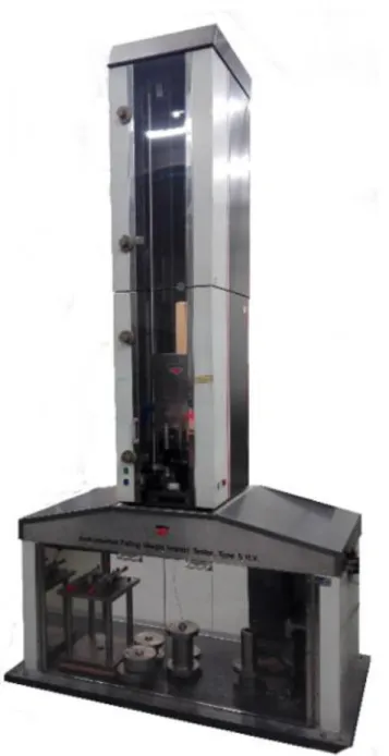
Before deciding to develop its own drop weight machine, ADFEUP used a Rosand IFW5 (Figure 2.9), which is located in FEUP´s testing laboratory, to carry out its studies. However, this drop weight machine proved too limited for the experiments that the group wanted to do, since its maximum energy is 300 J and its maximum velocity on impact is 4 m/s. The desire to design a drop weight machine grew, not only for the necessity of means to continue those experiments but also for academic purposes, enabling students to consolidate their knowledge during their master’s in mechanical engineering
Like in every project, the initial point was to design the main structure of the machine according to the specifications needed, which were defined by Castro [3], Barbosa [4] and the ADFEUP´s members at that time. These specifications were as it follows:
• Maximum energy on impact of 700 J;
• Minimum energy on impact of 50 J (at maximum velocity); • Maximum velocity of 5 m/s;
• Anvil positioning resolution of 1mm.
After the validation of the designed structure, Ramos [5] mounted the initial structure and implemented various important sub-systems. The sub-systems in question are an upper motor and transmission mechanism to move the carriage, a velocity acquisition sub-system and an anvil-impactor assembly. Ramos [5] also chose some sensors and made a pneumatic circuit to control the cylinder in charge of the drop weight release.
Figure 2.9 - FEUP´s Rosand IFW5 drop weight machine.
Sousa [6] was responsible for the initial electrical circuit assembly, a primordial command sequence to control the machine and the design of a PID controller that can position the carriage accurately. Sousa [6] also started the design of an ARS that would later be modified, validated and implemented by the work of this thesis, described in chapter 3.
Although a functioning machine was received in the beginning of this dissertation, there were still many implementations to be added and adjustments to be made in the electrical and pneumatic circuits, as well as in the control sequence. The final product of the four previous dissertations is presented in Figure 2.10.
Figure 2.10 - ADFEUP´s drop weight machine initial state. Lifting sub-system Lifting sub-system Anvil-impactor assembly Anvil-impactor assembly Carriage Carriage Velocity acquisition sub-system Velocity acquisition
sub-system Specimen fixing
structure
Specimen fixing structure
17
Chapter 3
Developed Sub-Systems
This chapter describes the designing and the validation process for two new implementations: the ARS and the anvil-impactor assembly.
3.1. Anti-rebound sub-system (ARS)
As it was previously said, Sousa [6] made an initial design of an ARS, however that mechanism had some flaws that had to be corrected. In addition, no mechanical parts´ drawings were made and no materials to fabricate the parts were chosen. As such, the initial tasks for this dissertation were to carefully analyse and correct his work, to make the mechanical parts´ drawings, that can be seen in Appendix A, and to choose all the materials for their fabrication. All these tasks were done with the help of SolidWorks 2018 and the final design of the ARS can be seen in Figure 3.1.
This ARS is a mechanism that consists in two rotating arms, fixed at each column of the machine, that will hold the anvil-impactor assembly after the first impact on the specimen, preventing the test results to be influenced by consequent rebounds. This way, the tests performed on this drop weight machine can give accurate and useful data about the adhesive joint tested. The arms work on the principle of a lever and each one is actuated by one pneumatic cylinder fixed on the structure of the machine. When the cylinders are extended the ARS is considered in the active position and when they are retracted is considered in the inactive position, like shown in Figure 3.2. If, at any time, an emergency is declared, the ARS will act. For example, if an emergency button is pressed while the anvil is falling, the ARS will hold the anvil preventing it from damaging the specimen. To be able to do that, this mechanism also has a pair of shock-absorbers in each arm that should be able to dissipate all the energy when the heaviest drop mass is released from the highest point of the anvil´s stroke. In case of energy failure the springs of the shock absorber will force the rotation of the arms to a safe position.
Figure 3.2 - The two positions of the ARS.
3.1.1. Rotating Structure
The rotating structure of the ARS is responsible for stopping the anvil and, because of that, is going to be positioned where the most stress concentrates. Therefore, the designed structure needs to be strong enough to withstand impact loads of the falling anvil and light weighted so it has a reduced inertia and can be quickly positioned. The main parts that assemble this structure are presented in Figure 3.3.
Figure 3.3 - Rotating structure of the ARS. Active (safety) position
Active position
Inactive (test) position
Inactive position Impact axle Specimen fixing structure L shaped arms Needle bearings Shock absorber-pads Actuation connection Specimen fixing structure Actuation axle Covers
3.1.1.1. Main Body
The main body´s parts are the ones that contribute the most for the weight of the ARS, thus, to meet the light weight requirement, they were fabricated from aluminium alloy plates. Those aluminium alloy plates were the AW 7075 - T651 (used for the L shaped arms) and the AW 6082 - T651 (used for the covers), which were bought from KMS [16].
3.1.1.2. Needle Bearings
The rotating structure only contacts with the fixed structure by means of three components which are the shock-absorbers, the pneumatic actuators and the bearings. Since the shock-absorbers can´t always follow the arm´s rotating movement, they break contact with it and, when that occurs, only the bearings and the pneumatic actuator contact with the fixed structure. To try to preserve the pneumatic actuator, the chosen bearings must withstand the full impact load capacity of the machine, which Ramos [5] calculated to be 66.88 kN. This value represents the transmitted force to the levelling foots and although this will not be the load applied on the bearings, it was the one used because it´s the highest value found in the structure of the machine. So, considering this value, a safety coefficient of 3.5and that the ARS has 4 bearings, each bearing should withstand a load around 60 kN.
In addition to being able to handle the high impact loads mentioned above, the chosen bearings should also be compact, due to the geometry of the parts that assemble the ARS. The SKF® NKI 35/20 TN needle bearings [17], shown in Figure 3.4, were chosen because they combine a high radial static load rating with the possibility to be mounted in a compact volume. The characteristics of these needle bearings are shown in Table 3.1 and their implementation can be seen in the ARS assembly´s drawings in Appendix A.
Figure 3.4 - SKF® NKI 35/20 TN needle bearing [17].
Table 3.1 - NKI 35/20 TN needle bearing properties [17].
m (kg) Mass
Cr (kN)
Radial dynamic load rating
C0r (kN)
Radial static load rating
Pu (kN)
Radial fatigue limit load
3.1.1.3. Impact and Actuation Axles
The impact axle, as the name suggests, is the component that directly collides with the falling anvil, whether during a rebound or a fall from one of the points of its stroke. Therefore, in order to choose the material from which this axle is going to be fabricated, one has to consider the worst-case scenario, which happens when the anvil falls from the highest point with the heaviest drop mass attached and collides with the said axle. Thus, it must be considered that the drop mass of the anvil is 56 kg and is going to fall from 1.27 m. The selected material was the N540 stainless steel from UniversalAfir [18], since it´s a material capable of withstand high loads and also because it´s not very influenced by corrosion over time. Since the actuator axle doesn’t require such a high-performance material, the M310 RD stainless steel from UniversalAfir [18] was chosen.
To validate the choice made, a simulation, based on a finite element analysis, using
SolidWorks 2018 had to be made. However, before doing such, the maximum impact
force, 𝐹𝐴,𝑚𝑎𝑥, had to be calculated by making a dynamic study of the interaction between the ARS and the anvil impactor assembly.
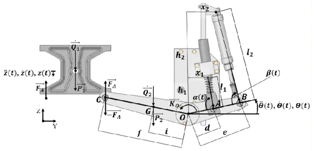
To initiate this dynamic study, a free body diagram (see Figure 3.5) was defined to identify all the forces at stake in this interaction.
By analysing both bodies separately, starting by the anvil-impactor assembly and knowing 𝑃1 ⃗⃗⃗ = [ 00 −𝑚1∙ 𝑔 ] ; 𝑄⃗⃗⃗⃗ ̇ = [1 0 0 −𝑚1∙ 𝑧̈(𝑡) ] ; 𝐹⃗⃗⃗⃗ = [𝐴 0 0 2𝐹𝐴 ] ; (3.1)
Where 𝑚1, 𝑔, 𝑧̈(𝑡) and 𝐹𝐴 represent the drop mass, the gravity´s acceleration, the drop
mass acceleration throughout time and the absolute value of the force transmitted to each of the ARS´ arms, respectively.
Knowing that the sum of the external forces (∑𝐹⃗⃗⃗⃗⃗⃗⃗⃗ ) equals the sum of the quantities 𝑒𝑥𝑡 of acceleration (∑𝑄⃗ ̇):
We can easily achieve the following expression:
Now, analysing the ARS sub-system we obtain the following vectors for the displacements of the represented points (A, B, C and G):
Where 𝑑, 𝑒, 𝑓 and 𝑖 are the distances between the arm´s axle and the points A, B, C and G, respectively, and 𝛳(𝑡) represents the angular position of the arm throughout time, being the main degree of freedom in this sub-system.
It´s possible to define the vectors for the velocities and accelerations that will later be needed by deriving some of the previous vectors:
∑ 𝐹⃗⃗⃗⃗⃗⃗⃗⃗ = ∑ 𝑄⃗ ̇ ⇔ 𝑃𝑒𝑥𝑡 ⃗⃗⃗ + 𝐹1 ⃗⃗⃗⃗ = 𝑄𝐴 ⃗⃗⃗⃗ ̇ 1 (3.2) 𝐹𝐴= 𝑚1 (𝑔 − 𝑧̈(𝑡)) 2 (3.3) 𝑂𝐴⃗⃗⃗⃗⃗ = [ 0 𝑑 ∙ cos (𝛳(𝑡)) 𝑑 ∙ sen (𝛳(𝑡)) ] ; 𝑂𝐵⃗⃗⃗⃗⃗ = [ 0 𝑒 ∙ cos (𝛳(𝑡)) 𝑒 ∙ sen (𝛳(𝑡)) ] ; (3.4) 𝑂𝐶⃗⃗⃗⃗⃗ = [ 0 −𝑓 ∙ cos (𝜋 6− 𝛳(𝑡)) 𝑓 ∙ sen (𝜋 6− 𝛳(𝑡))] ; 𝑂𝐺⃗⃗⃗⃗⃗ = [ 0 −𝑖 ∙ cos (𝜋 6− 𝛳(𝑡)) 𝑖 ∙ sen (𝜋 6− 𝛳(𝑡))] ; (3.5) 𝑂𝐴⃗⃗⃗⃗⃗ ̇ = ⌊ 0 −𝑑 ∙ 𝛳̇(𝑡) ∙ sen (𝛳(𝑡)) 𝑑 ∙ 𝛳̇(𝑡) ∙ cos (𝛳(𝑡)) ⌋ ; 𝑂𝐺⃗⃗⃗⃗⃗ ̇ = [ 0 −𝑖 ∙ 𝛳̇(𝑡) ∙ sen (𝜋 6− 𝛳(𝑡)) −𝑖 ∙ 𝛳̇(𝑡) ∙ cos (𝜋 6− 𝛳(𝑡))] ; (3.6)
Where 𝛳̇(𝑡) and 𝛳̈(𝑡) are the first and second derivate of 𝛳(𝑡), which also means that they represent the angular velocity and the angular acceleration of the ARS arm throughout time, respectively.
The forces applied on the ARS are its own weight (𝑃⃗⃗⃗⃗ ), the impact force (𝐹2 ⃗⃗⃗⃗ ), 𝐴 cylinder´s force (𝐹⃗⃗⃗⃗⃗⃗⃗⃗ ), shock-absorber force (𝐹𝐶𝑦𝑙. ⃗⃗⃗⃗⃗⃗⃗⃗ ) and the dynamic momentum (𝐾𝐴𝑏𝑠. ⃗⃗⃗⃗⃗ ): 𝑂
𝑄2 ⃗⃗⃗⃗ ̇ = 𝑚2× 𝑂𝐺⃗⃗⃗⃗⃗ ̈ = [ 0 −𝑚2∙ 𝑖 ∙ 𝛳̈(𝑡) ∙ sen (𝜋 6− 𝛳(𝑡)) + 𝑚2∙ 𝑖 ∙ 𝛳̇ 2(𝑡) ∙ cos (𝜋 6− 𝛳(𝑡)) −𝑚2∙ 𝑖 ∙ 𝛳̈(𝑡) ∙ cos (𝜋 6− 𝛳(𝑡)) − 𝑚2∙ 𝑖 ∙ 𝛳̇ 2(𝑡) ∙ sen (𝜋 6− 𝛳(𝑡))] ; (3.10)
Where 𝑚2, 𝐹𝑐𝑦𝑙, 𝐹𝑎𝑏𝑠, 𝐼𝑥𝑥, 𝛼 (𝑡) and 𝛽(𝑡) represent the ARS´s mass, the cylinders
force, the shock-absorbers force, the moment of inertia in the ARS centre of mass, the 𝑂𝐺 ⃗⃗⃗⃗⃗ ̈ = [ 0 −𝑖 ∙ 𝛳̈(𝑡) ∙ sen (𝜋 6− 𝛳(𝑡)) + 𝑖 ∙ 𝛳̇ 2(𝑡) ∙ cos (𝜋 6− 𝛳(𝑡)) −𝑖 ∙ 𝛳̇(𝑡) ∙ cos (𝜋 6− 𝛳(𝑡)) − 𝑖 ∙ 𝛳̇ 2(𝑡) ∙ sen (𝜋 6− 𝛳(𝑡))] ; (3.7) 𝑃2 ⃗⃗⃗⃗ = [ 00 −𝑚2∙ 𝑔 ] ; 𝐹⃗⃗⃗⃗ = [𝐴 0 0 −𝐹𝐴 ] ; 𝐹⃗⃗⃗⃗⃗⃗⃗⃗ = [𝐶𝑦𝑙. 0 𝐹𝑐𝑦𝑙∙ cos (𝛽(𝑡)) −𝐹𝑐𝑦𝑙∙ 𝑠𝑒𝑛 (𝛽(𝑡)) ] ; (3.8) 𝐹𝐴𝑏𝑠. ⃗⃗⃗⃗⃗⃗⃗⃗ = [ 0 𝐹𝑎𝑏𝑠∙ cos (𝛼(𝑡)) −𝐹𝑎𝑏𝑠∙ sen (𝛼(𝑡)) ] ; (3.9) 𝐻𝐺 ⃗⃗⃗⃗⃗ = [𝐼𝑥𝑥 ∙ 𝛳̇(𝑡)0 0 ] ; 𝐾⃗⃗⃗⃗⃗ = 𝐻𝐺 ⃗⃗⃗⃗⃗ ̇ = [𝐺 𝐼𝑥𝑥∙ 𝛳̈(𝑡)0 0 ] ; (3.11) 𝐾𝑂 ⃗⃗⃗⃗⃗ = 𝐾⃗⃗⃗⃗⃗ + 𝑂𝐺𝐺 ⃗⃗⃗⃗⃗ × 𝑄⃗⃗⃗⃗ ̇ = [2 𝐼𝑥𝑥∙ 𝛳̈(𝑡) + 𝑚2∙ 𝑖2∙ 𝛳̈(𝑡) 0 0 ] ; (3.12)
angle between the shock-absorbers and the ARS´s arm and the angle between the cylinder and the ARS´s arm, respectively.
It is also known that the shock absorber force is proportional to the velocity, so 𝐹⃗⃗⃗⃗⃗⃗⃗⃗ 𝐴𝑏𝑠. can also be defined as:
After defining all these vectors and knowing that the sum of the external momentums (∑𝑀⃗⃗⃗⃗⃗⃗⃗⃗⃗ ) equals the sum of the dynamic momentums (∑ 𝐾𝑂𝑒𝑥𝑡 ⃗⃗⃗⃗⃗ ), it´s possible to use the 𝑂
following expression:
∑ 𝑀⃗⃗⃗⃗⃗⃗⃗⃗⃗ = ∑ 𝐾𝑂𝑒𝑥𝑡 ⃗⃗⃗⃗⃗ ⇔ 𝑂
𝑂𝐴⃗⃗⃗⃗⃗ × 𝐹⃗⃗⃗⃗⃗⃗⃗⃗ + 𝑂𝐵𝐴𝑏𝑠. ⃗⃗⃗⃗⃗ × 𝐹⃗⃗⃗⃗⃗⃗⃗⃗ + 𝑂𝐶𝐶𝑦𝑙. ⃗⃗⃗⃗⃗ × 𝐹⃗⃗⃗⃗ + 𝑂𝐺𝐴 ⃗⃗⃗⃗⃗ × 𝑃⃗⃗⃗⃗ = 𝐾2 ⃗⃗⃗⃗⃗ 𝑂 (3.14)
That leads to:
(𝐼𝑥𝑥+ 𝑚2∙ 𝑖2) ∙ 𝛳̈(𝑡) =
𝑐 ∙ 𝑑2∙ 𝐹
𝑎𝑏𝑠(sen(𝛳(𝑡)) 2
∙ cos(𝛼 (𝑡)) − cos(𝛳(𝑡))2∙ sen(𝛼 (𝑡))) ∙ 𝛳̇(𝑡) −𝑒 ∙ 𝐹𝑐𝑦𝑙(cos(𝛳(𝑡)) ∙ sen(𝛽(𝑡)) + sen(𝛳(𝑡)) ∙ cos(𝛽(𝑡)))
+𝑓 ∙ 𝐹𝐴∙ cos (𝜋
6− 𝛳(𝑡)) + 𝑖 ∙ 𝑚2∙ 𝑔 ∙ cos ( 𝜋
6− 𝛳(𝑡)) (3.15)
In order to simplify this expression, the geometric relations between the different degrees of freedom must be defined.
{𝑑 ∙ cos(𝛳(𝑡)) = 𝑥1+ 𝑙1(𝑡) ∙ cos(𝛼(𝑡)) 𝑑 ∙ 𝑠𝑒𝑛(𝛳(𝑡)) = ℎ1− 𝑙1(𝑡) ∙ sen(𝛼(𝑡))⇔ { 𝛼(𝑡) = 𝑡𝑎𝑛−1( 𝑑 ∙ 𝑠𝑒𝑛(𝛳(𝑡)) − ℎ1 −(𝑑 ∙ cos(𝛳(𝑡)) − 𝑥1)) 𝑙1(𝑡) = 𝑑 ∙ cos(𝛳(𝑡)) − 𝑥1 cos (𝑡𝑎𝑛−1( 𝑑 ∙ 𝑠𝑒𝑛(𝛳(𝑡)) − ℎ1 −(𝑑 ∙ cos(𝛳(𝑡)) − 𝑥1))) (3.16) 𝐹𝐴𝑏𝑠. ⃗⃗⃗⃗⃗⃗⃗⃗ = [ 0 −𝑐 ∙ 𝑑 ∙ cos (𝛼(𝑡)) ∙ sen (𝛳(𝑡)) ∙ 𝛳̇(𝑡) −𝑐 ∙ 𝑑 ∙ sen (𝛼(𝑡)) ∙ cos (𝛳(𝑡)) ∙ 𝛳̇(𝑡) ] (3.13)
Where 𝑥1, 𝑥2, ℎ1, ℎ2, 𝑙1 and 𝑙2 are geometric parameters that can be seen in Figure 3.5.
Substituting Expression (3.20) in Expression (3.3) leads to:
Finally, substituting Expression (3.21) in Expression (3.15) it´s possible to obtain the following expression:
𝛳̈(𝑡) = 𝑐 ∙ 𝑑2∙ 𝐹
𝑎𝑏𝑠(sen(𝛳(𝑡)) 2
∙ cos(𝛼 (𝑡)) − cos(𝛳(𝑡))2∙ sen(𝛼 (𝑡))) ∙ 𝛳̇(𝑡) 𝐼𝑥𝑥+ 𝑚2∙ 𝑖2+𝑓2 ∙ 𝑚1 2 ∙ cos ( 𝜋 6 − 𝛳(𝑡)) + 𝑓 ∙ 𝑚1∙ 𝑔 2 ∙ cos ( 𝜋 6 − 𝛳(𝑡)) + 𝑖 ∙ 𝑚2∙ 𝑔 ∙ cos ( 𝜋 6 − 𝛳(𝑡)) 𝐼𝑥𝑥+ 𝑚2∙ 𝑖2+𝑓2∙ 𝑚1 2 ∙ cos ( 𝜋 6 − 𝛳(𝑡))
−𝑒 ∙ 𝐹𝑐𝑦𝑙(cos(𝛳(𝑡)) ∙ sen(𝛽(𝑡)) + sen(𝛳(𝑡)) ∙ cos(𝛽(𝑡))) 𝐼𝑥𝑥+ 𝑚2∙ 𝑖2+𝑓2∙ 𝑚1 2 ∙ cos ( 𝜋 6 − 𝛳(𝑡)) (3.22) {𝑒 ∙ cos(𝛳(𝑡)) = 𝑥2+ 𝑙2(𝑡) ∙ cos(𝛽(𝑡)) 𝑒 ∙ 𝑠𝑒𝑛(𝛳(𝑡)) = ℎ2− 𝑙2(𝑡) ∙ sen(𝛽(𝑡))⇔ { 𝛽(𝑡) = 𝑡𝑎𝑛−1( 𝑒 ∙ 𝑠𝑒𝑛(𝛳(𝑡)) − ℎ2 −(𝑒 ∙ cos(𝛳(𝑡)) − 𝑥2)) 𝑙2(𝑡) = 𝑒 ∙ cos(𝛳(𝑡)) − 𝑥2 cos (𝑡𝑎𝑛−1( 𝑒 ∙ 𝑠𝑒𝑛(𝛳(𝑡)) − ℎ2 −(𝑒 ∙ cos(𝛳(𝑡)) − 𝑥2))) (3.17) 𝑧(𝑡) = 𝑓 ∙ 𝛳(𝑡) (3.18) 𝑧̇(𝑡) = 𝑓 ∙ 𝛳̇(𝑡) (3.19) 𝑧̈(𝑡) = 𝑓 ∙ 𝛳̈(𝑡) (3.20) 𝐹𝐴 = 𝑚1 (𝑔 − 𝑓 ∙ 𝛳̈(𝑡)) 2 (3.21)
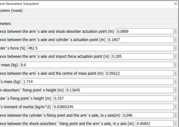
Expression (3.22) was, then, implemented in Matlab Simulink to create a dynamic model of the interaction between the ARS and the anvil-impactor sub-system, which can be viewed in Appendix C at its full extent, as well as the results. Notice that Expressions (3.16) and (3.17) weren´t substituted, so that that Expression (3.22) can be better precepted, although they were taken into consideration in Matlab Simulink model. However, before running the model, it´s still needed to attribute values to the parameters at stake. Most of the parameters can be obtained by consulting the SolidWorks 2018´s drawings, such as the distances between the arm´s axle and the forces´ actuation points or the moment of inertia of the arm. The force applied by the pneumatic cylinder is indicated in its data sheet, which is 482.5 N when the air is pressurized at 6 bar. In the case of the shock-absorber chosen by Sousa [6], ACE MC3350EUM-0 [19] (see Figure 3.6), there is no indication about its damping coefficient or its force, however the manufacturer informs that the force of this component is constant along the whole stroke, as it can be seen in Figure 3.7.
Figure 3.6 - ACE MC3350EUM-0 [19].
Figure 3.7 - Stopping force along industrial shock-absorber´s stroke [20].
Knowing this, we can achieve the following expression:
Where 𝐸𝐴𝑏𝑠. is the dissipated energy by the shock-absorbers per cycle and 𝑥 is the shock-absorbers´ stroke. 𝐸𝐴𝑏𝑠. = ∫ 𝐹𝐴𝑏𝑠.(𝑠) ∙ 𝑑𝑠 𝑥 0 ⇔ 𝐸𝐴𝑏𝑠.= 𝐹𝐴𝑏𝑠.∙ 𝑥 ⇔ 𝐸𝐴𝑏𝑠. 𝑥 = 𝐹𝐴𝑏𝑠. (3.23)
As it was previously said, the shock-absorber force is proportional to the velocity:
By combining both expressions, the damping coefficient can now be estimated by:
Consulting the shock absorbers data sheet, the values for 𝐸𝐴𝑏𝑠. and 𝑥 are found and applied like shown in Expression 3.26:
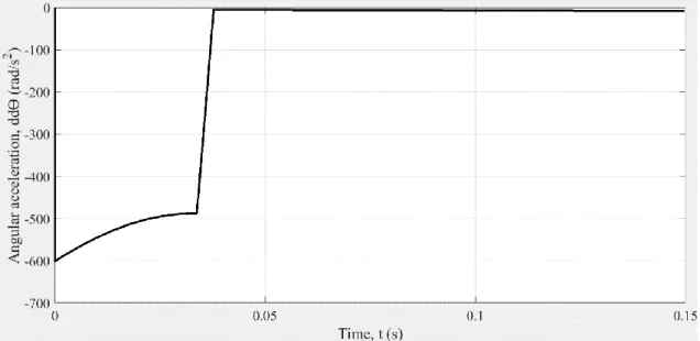
This coeficient is then used in the first term of the Simulink model of Expression 3.22. Now that the values for all parameters are known, they are inserted in the developed
Matlab Simulink model, like shown in Figure 3.8. By running the model, the results for
the angular acceleration throughout time, 𝛳̈(𝑡), are obtained. Those results can be consulted in Figure 3.9. 𝐹𝐴𝑏𝑠. = 𝑐 ∙ 𝑥̇ (3.24) 𝑐 = 𝐸𝐴𝑏𝑠. 𝑥 ∙ 𝑥̇ (3.25) 𝑐 = 2 ∙ 330 0.0486 ∙ 𝑥̇ = 2 ∙ 330 0.0486 ∙ 𝑑 ∙ 𝛳̇ (3.26)
Figure 3.8 - Parameters´ values inserted in the developed Matlab Simulink model, considering the maximum drop weight.
Now, it is finally possible to calculate 𝐹𝐴,𝑚𝑎𝑥, using Expression (3.3), needed to run
the simulation on SolidWorks 2018, and confirm if the material for the impact axles was correctly chosen. 𝐹𝐴,𝑚𝑎𝑥 = 𝑚1 × (𝑔 − 𝑓 ∙ 𝛳̈𝑚𝑎𝑥(𝑡)) 2 = 56 × (9.81 − 0.285 × (−600)) 2 = 5062.68 𝑁 (3.27)
Inserting this value in SolidWorks 2018´s simulation parameters, it´s possible to obtain the results for the factor of safety, shown in Figure 3.10. The minimum value found for the factor of safety was 6.46, granting that the material will keep its integrity with the impacts.
Figure 3.9 - Angular acceleration obtained in the developed Matlab Simulink model, considering the maximum drop weight.
Figure 3.10 - Factor of safety obtained when a 5063 𝑁 is applied to the ARS´ rotating structure, recurring to SolidWorks 2018.
3.1.1.4. Actuation Axle Connector
In order to move the ARS, the pneumatic cylinder must act on the actuator axle, however the rod eyes that Festo provides do not meet the diameter needed for this axle. To solve this problem, an intermediary part had to be designed by Sousa [6], but it had to be modified because this designed part would interfere with the rod eye, meaning that there wasn’t enough space for both. The final design of this part is shown in the Figure 3.11.
It consists in an aluminium alloy part, fabricated from an aluminium alloy plate, AW 6082 - T651, obtained from KMS [16]. It is comprised by two holes, the smallest one is for the axle of the rod eye, which has a 10 mm diameter, and the largest one is for the actuation axle. To guarantee that this part wouldn’t rotate and that it would transmit the force to the actuation axle, this component has a slot to allocate a parallel key.
3.1.1.5. Shock-Absorbers Pads
The contact points between the ARS´s arms and the shock-absorbers are where most of the stress will build up and it´s important that the damping force always acts perpendicularly to the arms. To be able to do this, special pads (Figure 3.12) were designed and fabricated from AW 6082 - T651, bought from KMS [16].
Since the cylinders can extend faster than the shock-absorbers, the alignment pads could rotate and be misplaced, making the damping force impossible to act
Figure 3.11 - New design of the actuation axle connector, made in SolidWorks 2018.
perpendicularly. To avoid this from happening, polyurethane parts with a specific geometry were made to be placed under the pads, in order to force them to be aligned with the absorbers when the mentioned components break contact. As the shock-absorbers act on the pads, the polyurethane parts are easily compressed and, therefore, don’t interfere with the functioning of the machine.
3.1.2. Fixed Structure
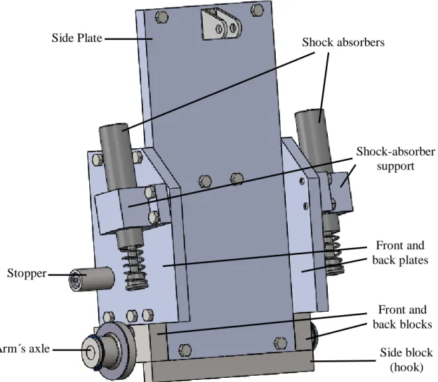
The fixed structure, represented in Figure 3.13, is the link between the ARS and the main structure of the drop weight machine. It is composed by three aluminium alloy plates, two of them to mount the mechanical stoppers, that prevent the rotation of the arm to a certain angle, and the shock-absorbers and the other is to mount the pneumatic actuator.
All these plates are fixed on the structure of the drop weight machine using screws and T-nuts. Although this type of mechanical connection can hold the plates against the profiles, they shouldn’t be subjected to vertical forces because they are likely to slip. This problem was solved by designing three steel blocks that will discharge the vertical forces to the main structure of the machine. Additionally, two of these blocks will position the axles to mount the needle bearings.
Figure 3.13 - Final design of the ARS´ fixed structure, made in SolidWorks 2018. Side Plate Specimen fixing structure Shock absorbers Specimen fixing structure Shock-absorber support Specimen fixing structure Stopper Specimen fixing structure Arm´s axle Specimen fixing structure Front and back plates Specimen fixing structure Front and back blocks Specimen fixing structure Side block (hook) Specimen fixing structure
To connect all the parts that assemble the ARS, the materials presented in Table 3.2 are used.
Table 3.2 - Fasteners used to assemble the ARS.
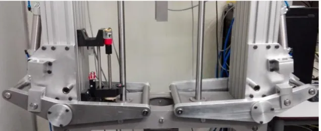
After the mechanical drawings and materials of the parts that comprise the ARS were defined, it was possible to manufacture them and to mount this mechanism. However, it´s not completely assembled, since it still lacks the shock-absorbers in its construction, which haven´t yet been delivered. For this reason, this sub-system´s functioning is yet to be tested. The currently implemented ARS´s arrangement can be seen in Figure 3.14.
Element Norm Qt. Keys C ISO/R773 6x6x25 4 A ISO/R773 6x6x32 2 Screws ISO 4017 - M8X30 -12.9 24 ISO 4762 - M6x30 - 12.9 6 ISO 4762 - M8x25 - 12.9 16 ISO 4017 - M6x20 - 12.9 12 ISO 4762 - M8x50 - 12.9 4 ISO 4017 - M8x25 - 12.9 28 ISO 4017 - M6x16 - 12.9 4 DIN 471 - 20x1.2 16 Circlips DIN 471 - 35x1.5 4 DIN 471 - 10x1 4 Galvanized
T-nuts Bosch´s norm 44
3.2. Anvil-impactor sub-system
The anvil-impactor sub-system assembles all the components that contribute for the drop mass. Initially, the designed assembly was only comprised by an impactor, in form of a puncture, and the anvil, as shown in Figure 3.15. However, there was the need to implement a new impactor to adapt to a new and more rigid specimen fixing structure (see Figure 3.16), designed by one of the ADFEUP´s members, and a pair of piezoelectric sensors, that will measure the evolution of acceleration and force throughout time.
Normally, drop weight machines have one sensor to either measure the force or to measure the acceleration, since one can be deducted from the other. However, most of those machines don´t use pre-calibrated sensors, meaning that they have to be recalibrated before each usage, like what happens with Rosand IFW5 machine. Since that process is made by the operator, who can´t guarantee the same reference for each calibration, the associated error of the measurement increases, which will influence the results obtained. To avoid that source of error in the impact test´s results, this drop weight machine will use pre-calibrated sensors. However, if only one of these sensors is used, in long term, it can lose its reference and provide wrong data without the user´s knowledge. So, to ensure that the collected data is reliable, this drop weight machine uses a pre-calibrated piezoelectric accelerometer and a pre-calibrated piezoelectric load cell. This way, the obtained results on both sensors can be compared and, if their information matches, it can be assumed that the measurements are reliable.
Figure 3.15 - Initial anvil-impactor assembly.
In order to completely characterize an adhesive joint under impact conditions, one should measure the force and the displacement. The force can be obtained directly by the load cell or by multiplying the drop mass by the accelerometer´s measured impact acceleration. The displacement could be obtained by double integrating the measured acceleration, using either sensor. However, since we are dealing with AC coupled sensors, which have an intrinsic decaying function when integrating data in real time, there is an associated error leading to wrong calculated displacements [21].
There are other ways to measure the displacement, like using a high-speed camera, however, for this kind of solution, the target should be very illuminated, which is hard to implement due to the specimen fixing structure.
For these reasons, the displacement will be obtained after the test is done, integrating the resulting acceleration data, gathered by both sensors. This is a temporary solution, since, in the future, a new tool, equipped with sensors that can directly measure the displacement (LVDT or linear potentiometer), will be attached to the new specimen fixing structure.
After considering the mounting of the sensors, a solution for the new anvil-impactor assembly was designed in SolidWorks 2018, Figure 3.17. The mechanical parts´ drawings for this assembly are presented in Appendix B.
To validate the new anvil-impactor assembly proposed, it´s important to have some considerations in mind. The most important one is to know what´s the measuring range needed for each sensor. The other aspects to consider are explained in section 4.2.
When considering which accelerometer is to be chosen, one should think that accelerations that result from an impact can be somewhat unpredictable. Furthermore, it may be needed to test materials other than adhesive joints, which have different rigidities, resulting in different impact behaviours. So, in order to not limit this drop weight machine in terms of what materials can be tested, the selected accelerometer must be able to withstand and measure high impact accelerations.
Load cell Load cell Accelerometer Accelerometer New impactor New impactor
Figure 3.16 - New specimen fixing structure. Figure 3.17 - New anvil-impactor assembly design, made in SolidWorks 2018.
Sigle lap joint Load cell Part to be impacted Load cell
Now, in what the load cell concerns, there are two possible ways that this sensor is going to be loaded: The anvil-impactor assembly hits the specimen, subjecting the load cell to compressive forces, or is grabbed by the ARS, subjecting the load cell to tensile forces. After gathering information about the highest recorded impact load on adhesive joints tested by ADFEUP´s members, it was concluded that this value was close to 35 kN, as Figure 3.18 demonstrates. So, the load cell should be able to measure compressive forces higher than the mentioned value.
Figure 3.18 - Graph of the displacements-load of carbon fibre reinforced polymer (CFRP) substrates tested under impact at different temperatures: room temperature (RT), low temperature (LT) and high temperature (HT) [22].
To know the tensile forces that the load cell should withstand, the linear acceleration, 𝑧̈, of the anvil-impactor assembly when it collides with the ARS´s axle must be known. Using the maximum angular acceleration, 𝛳̈𝑚𝑎𝑥., previously calculated in the dynamic study and Expression (3.20), 𝑧̈𝑚𝑎𝑥. comes:
The forces that contribute to the tensile load that the press force sensor will be subjected are the quantity of acceleration forces and the weight forces of the impactor and one steel plate, so it´s calculated by:
However, the maximum value of the angular acceleration, 𝛳̈𝑚𝑎𝑥., was obtained when
a drop mass of 56 kg is released from the highest point of the stroke and it´s also important 𝑧̈𝑚𝑎𝑥. = 0.285 × (−600) = −171 𝑚/𝑠2 (3.28) 𝐹𝑇𝑒𝑛𝑠.= 𝑄̇𝐼𝑚𝑝.+ 𝑃𝐼𝑚𝑝. + 𝑄̇𝑃𝑙𝑎𝑡𝑒+ 𝑃𝑃𝑙𝑎𝑡𝑒 = 𝑚𝐼𝑚𝑝,× (𝑧̈𝐼𝑚𝑝.+ 𝑔)+𝑚𝑃𝑙𝑎𝑡𝑒 × (𝑧̈𝐼𝑚𝑝.+ 𝑔) = 5.495 × (−171 − 9.81) + 0.039 × (−171 − 9.81) ≈ − 1000 𝑁 (3.29) 0 5 10 15 20 25 30 35 0 1 2 3 4 5 6 L oa d (k N ) Displacement (mm) RT LT HT
![Figure 2.1 - Stress distribution comparison between bonded surfaces using standard fasteners and adhesive materials [2]](https://thumb-eu.123doks.com/thumbv2/123dok_br/15706844.1068257/25.892.216.683.763.1091/figure-distribution-comparison-surfaces-standard-fasteners-adhesive-materials.webp)
![Table 2.1 - Studied properties of adhesive joints and associated types of test [7].](https://thumb-eu.123doks.com/thumbv2/123dok_br/15706844.1068257/26.892.172.709.639.908/table-studied-properties-adhesive-joints-associated-types-test.webp)
![Figure 2.4 - Basic setup and Lagrangian diagram for compressive tests on a SHPB machine [8].](https://thumb-eu.123doks.com/thumbv2/123dok_br/15706844.1068257/28.892.167.729.938.1125/figure-basic-setup-lagrangian-diagram-compressive-tests-machine.webp)
![Figure 2.6 - Basic setup and Lagrangian diagram for tensile tests on a SHPB machine [8]](https://thumb-eu.123doks.com/thumbv2/123dok_br/15706844.1068257/30.892.146.749.161.383/figure-basic-setup-lagrangian-diagram-tensile-tests-machine.webp)