Biologically inspired vision for indoor robot
navigation
M. Saleiro, K. Terzi´c, D. Lobato, J.M.F. Rodrigues, and J.M.H. du Buf
Vision Laboratory, LARSyS, University of the Algarve, 8005-139 Faro, Portugal, {masaleiro, kterzic, dlobato, jrodrig, dubuf}@ualg.pt
http://w3.ualg.pt/~dubuf/vision.html
Abstract Ultrasonic, infrared, laser and other sensors are being applied in robotics. Although combinations of these have allowed robots to navig-ate, they are only suited for specific scenarios, depending on their limita-tions. Recent advances in computer vision are turning cameras into useful low-cost sensors that can operate in most types of environments. Cam-eras enable robots to detect obstacles, recognize objects, obtain visual odometry, detect and recognize people and gestures, among other possib-ilities. In this paper we present a completely biologically inspired vision system for robot navigation. It comprises stereo vision for obstacle detec-tion, and object recognition for landmark-based navigation. We employ a novel keypoint descriptor which codes responses of cortical complex cells. We also present a biologically inspired saliency component, based on disparity and colour.
Keywords: Biologically Inspired Vision, Stereo Vision, Object Recog-nition, Robotics
1
Introduction
Many types of sensors are being used for robot navigation. Some can be cheap, such as infrared and ultrasonic rangefinders [12], RFID [12,7] and GPS [10,17], but others can be quite expensive, like laser rangefinders [13]. They allow ro-bots to acquire information about the environment within certain ranges and depending on certain environmental conditions. However, such sensors are not always appropriate if we want to build a robot that can adapt to changes in the complex world. The use of cameras as sensors offers new possibilities. Vision can provide information about odometry and obstacles in the path of the robot, or find landmarks [5] and objects along the path. A robot can also detect humans and interact with them by understanding their gestures. The advent of low-cost RGB-D sensors has spawned a lot of interest since they allow to get reliable depth maps effortlessly if compared to stereo vision [8,2]. However, such sensors also have their limitations, like the limited range and the fact that they can only be used indoors.
In order to build robots that may be able to interact with a dynamic environ-ment, a framework inspired by human cognition must be developed. This must integrate sensory information with a memory management model, with both
II
short- and long-term memory components [16]. Concerning sensory information, we can model processes in the human visual system, such as visual saliency, Focus-of-Attention (FoA) [14], optical flow [6], local and global gist [11], stereo vision and object recognition [18].
In previous work [16] we developed a minimalistic vision-based cognitive SLAM system comprising visual saliency, object segregation and object recog-nition. The vision processes were integrated with a cognitive memory structure composed of short- and long-term memories. The first one has a small capacity, storing only the necessary for immediate navigation. The latter stores important information, selected from short-term memory, for longer periods of time in order to use it for global navigation. The system also integrates a task management system for building complex tasks from simpler ones.
In this paper we integrate biologically inspired vision processes and replace some previously used components which were based on computer vision: SURF keypoints and descriptors for object recognition and Fast Saliency [3] algorithm for focus of attention. With the integration of fast multi-core processors and high capacity batteries in laptops these biologically inspired processes are finally mak-ing their way into real-time mobile robotics. As main contributions in this paper we present new biologically inspired approaches for (a) keypoint descriptors, (b) stereo vision, (c) visual saliency and (d) object recognition. These approaches are based on complex cell responses obtained from a cortical V1 model [18,14]. However, the main goal of this paper is to address the feasibility of using an integrated visual framework in real time robot navigation.
The rest of this paper is organised as follows: Section 2 describes the visual processes: keypoint descriptors, stereo vision, saliency and object recognition. Section 3 presents the robot platform, tests and results. Section 4 addresses conclusions and discusses further work.
2
Biologically inspired vision for robot navigation
In this section we present a system for robot navigation which makes use of recent advances in modelling early cortical vision processes. Instead of SURF keypoints and descriptors commonly used in robotics, we developed a simple biological descriptor based on the responses of complex cells of V1 cortex which are also used for keypoint extraction [14]. We apply a biological stereo algorithm in order to improve obstacle detection and to eliminate the restriction of using artificial sandboxes. Disparity maps are combined with colour information to cre-ate saliency maps for object segregation. Finally, the novel keypoint descriptors are used to perform object recognition. In our tests we employed a Bumblebee-2 colour camera (BB298S2C-60) with a maximum resolution of 1024 × 768, a focal length of 6mm and a 43° horizontal field-of-view.
2.1 Multi-scale keypoints and biological keypoint descriptor
In cortical area V1 there are simple, complex and end-stopped cells [15], which play an important role in coding the visual input. They can be used to extract
III
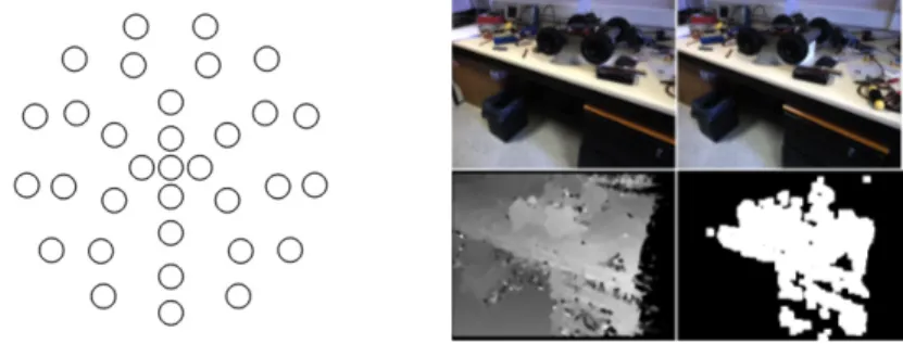
multi-scale line, edge and keypoint information: keypoints are line/edge crossings or junctions, but also blobs [14]. To use extracted keypoints for matching, we developed a simple binary descriptor which encodes complex cell responses ac-cording to a sampling pattern (see Fig. 1, left.) around a keypoint and compares them to the responses of the complex cells at the keypoint position. The use of these responses makes the descriptor very fast to compute because these are already calculated in the keypoint detection process [18]. Pairwise comparison of image intensities with similar sampling patterns has been successfully used in other binary descriptors such as BRIEF [4], BRISK [9] and FREAK [1].
Figure 1. Left: biological keypoint descriptor sampling pattern with 32 points radially distributed in 4 concentric circles. The radii of the circles are proportional to the scale λ = 4 of the keypoint. Right: stereo example. Top: left and right images. Bottom: filtered disparity map and binary obstacle map. In the disparity map brighter pixels correspond to closer regions and darker pixels to more distant ones.
We use a sampling pattern with 4 concentric circles, with the most distant circle having a radius equal to λ, where λ is the spatial wavelength of the Gabor filter used for modelling simple cells [18]. The smaller concentric circles have a radii of 0.2λ, 0.45λ and 0.75λ, respectively. Radial sampling patterns are com-monly used in other binary descriptors [4,9,1]. We stress that we only apply one scale (λ = 4 pixels) in this paper in order to achieve real-time performance on a portable computer. However, we apply 8 filter orientations equally spaced on [0, π].
At each sampling position we take the responses of the complex cells in all 8 orientations and compare each response with the response of the center cells with the same orientation. If the response of the center cell is larger, we code this with a binary “1”. Otherwise, we code it as a binary “0”. Since we use a total of 32 sampling positions and 8 orientations, each keypoint is coded by a 256-bit descriptor. Matching of two keypoints is done by simply calculating the Hamming distance between their descriptors.
2.2 Stereo Vision
Stereo vision is a fundamental process for robot navigation because it allows to detect open spaces, obstacles on its path and estimate the distance to those
IV
obstacles. Stereo vision is also useful for computing visual saliency. The stereo process employs the simple descriptors presented in Section 2.1.
In order to navigate and avoid obstacles, a robot only needs a coarse view of the obstacles and walls in front of it. A coarse disparity map can be calculated by downsizing the images captured from the left and right cameras. The algorithm is as follows: (a) resize the images to 160 × 120 pixels, (b) apply the descriptor previously presented to code every individual image pixel, (c) compare each pixel P in the left image to the next K pixels on the same line starting from the same position P , in the right image, and (d) using the Hamming distance, evaluate which of the K pixels is most similar to pixel P and use the horizontal displacement as the disparity value. Parameter K depends on the stereo camera used: we used K = 150. Since both descriptors and Hamming distances for matching are very fast to calculate, we can obtain a rough disparity map for real-time robot navigation. After calculating the disparity map we apply a median filter of size 5 × 5 to reduce noise due to wrong matches. In order to allow the robot to avoid obstacles and walls we threshold the disparity map and then apply a blob detection algorithm to locate nearby obstacles. This is illustrated in Fig. 1 (right).
2.3 Visual Saliency
Visual saliency is important for real-time vision, since it allows a robot to select important regions to process instead of processing entire images. Saliency maps are also useful for segregating objects from the background, reducing clutter and improving object recognition rates.
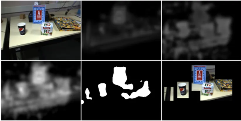
Figure 2. Visual saliency example. Left to right, top to bottom: input image, colour based saliency, disparity based saliency, combined maps, thresholded map and inter-esting regions. Although the book is more distant, its distinctive colours make it an interesting region to process.
Our new saliency component combines colour with disparity. We build a stack of 6 retinotopic maps representing different channels in CIE L*A*B colour-opponent space. The CIE L*A*B model is based on retinal cones and provides
V
a standard way to model colour opponency. The first three channels code the image in L*A*B colour space, thus represent white, green and blue. The other three channels are the complements of the first three channels, thus represent black, red and yellow.
After computing the retinotopic maps we apply blob-detection based on a stack of bandpass Difference of Gaussians (DoG) filter kernels with σ+ ∈
{5, 10, 20} and σ− = 2σ+. The same process is applied to the filtered disparity
map after thresholding to get only the nearest regions. Finally, we sum the in-dividual colour maps and the disparity map (Fig. 2). Since a saliency map does not need to be detailed, we compute it using the subsampled colour images for faster processing. After computing the final saliency map we threshold it and process only interesting regions for object recognition.
2.4 Object recognition
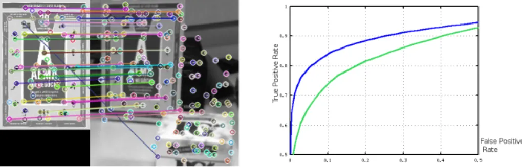
For object recognition we selected a small set of objects to which we apply the keypoint extraction and description algorithms. Resulting keypoint descriptor ar-rays are then stored in the robot’s memory for faster processing during runtime. During navigation, these descriptor arrays are matched to keypoint descriptors extracted from the images captured by one of the robot’s cameras. Since we use binary descriptors, matching is quickly done by calculating the Hamming distances. When 50% of all descriptors of a certain object can be matched, i.e., having a Hamming distance smaller than 48, the object is confirmed. A matching example is shown in Fig. 3.
Figure 3. Left: example of matching: the segregated book shown in Fig. 2. Right: comparison between our descriptor(green) and BRISK(blue) over 20000 patches.
In our preliminary tests we verified that our descriptors can be used for basic object recognition. We successfully used them to recognize 8 different objects (boxes, cups, book covers) under good lighting conditions. For object recognition we used λ = 8. For evaluation purposes we also used our descriptor for patch classification. We tested it on the Yosemite dataset. The graph on Fig. 3 shows a comparison between our descriptor and BRISK, which performs better. However, we emphasize that our descriptor uses half the bits that BRISK uses and has not yet been optimized in terms of redundancy, relevancy, coding and pooling.
VI
3
Tests and Results
3.1 The Robotic Platform
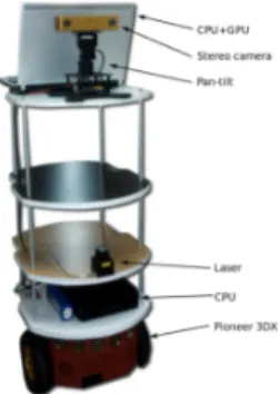
To test the developed system we used a child-sized Pioneer 3DX robot, equipped with a Bumblebee-2 stereo camera, a PhantomX robot turret for pan and tilt movement of the camera, and ultrasonic and laser rangefinder sensors (see Fig. 4). The range sensors are only used for emer-gency collision avoidance, not for navig-ation. A structure has been mounted on the robot in order to give it more height, providing the point of view of a child with a height of 1.20m. The robot has been set
up with ROS (Robot Operating System). Figure 4. Robotic platform used for testing.
3.2 Test results
For testing the stereo algorithm we placed the robot in a 60 meter long corridor and programmed it to go from one end to the other end and to avoid walls and obstacles, always trying to the initial orientation. Every time it detected an obstacle it move away from it. The corridor had varying lighting conditions, being dark in some parts, well lit in others with fluorescent lamps, which generate a lot of image noise, or with direct sunlight from the side. Along the corridor there were 7 obstacles with different sizes, shapes and colors, such as a table, a chair and cardboard and styrofoam boxes. During autonomous robot navigation we randomly placed ourselves in front of the robot. Other persons occasionally passed in front of the robot as well. In the middle of the corridor, it had a wider region with two pillars that the robot also had to avoid. We rearranged the obstacles in three different setups (A, B and C) and made 20 entire runs for each setup. The results can be seen on Table 1.
Table 1. Testing results of 60 runs in three different setups. Setup Successful runs Failed runs Success Rate
A 17 3 85%
B 16 4 80%
C 16 4 80%
During sixty runs the robot ran into obstacles only 11times. The major failure causes were: (a) moving obstacles in dark parts of the corridor (see Fig. 5); (b) navigating almost parallel to a blank wall due to the lack of texture and to the small FOV of the cameras; and (c) navigating in narrow spaces. Most of these problems can be easily solved by integrating the SLAM system that we previously developed which makes use of the pan and tilt system to build maps for local
VII
and global navigation. The stereo maps took an average of 0.085s to compute on a 2.4 GHz Intel quad core i7-4700HQ processor for the size of 160 × 120 pixels. For 320×240 it takes an average of 0.39s. However, the smaller resolution proved to be enough for obstacle avoidance.
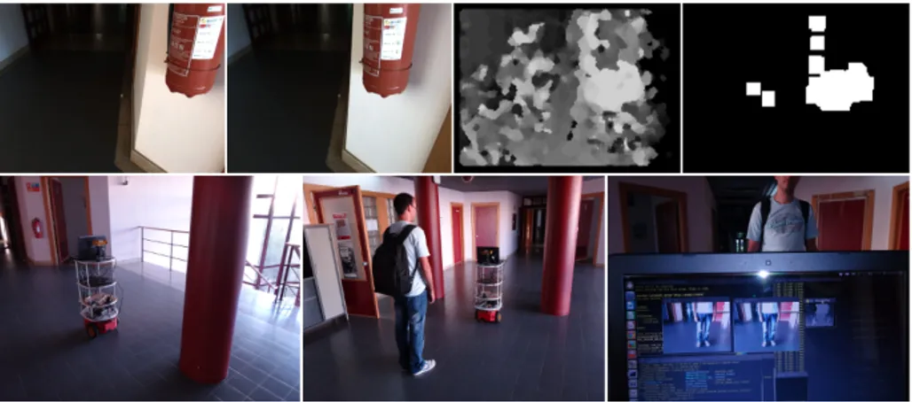
Figure 5. Corridor navigation examples. Top, left to right: left and right camera im-ages, disparity map and obstacle map. Bottom, left to right: robot detecting one of the pillars, robot detecting a person as an obstacle to avoid and screen of the computer showing the two images from the Bumblebee-2 camera and the disparity map.
4
Conclusions and further work
Our initial tests demonstrate that our biologically inspired system works quite well for vision-based robot navigation. Using the stereo algorithm, the robot was able to avoid the obstacles and walls in most testing runs. Visual saliency also en-abled the robot to select interesting image regions for further object recognition using our novel keypoint descriptors.
Regarding visual saliency, we are working to extend it by including other cues, such as texture, shape and motion. Motion can be quite useful for avoiding moving obstacles or humans.
Although the keypoint descriptor proved to be good enough for the simple tasks used in our experiments, we are still improving it to make it competitive with state-of-the-art keypoint descriptors. Other pooling and coding approaches could yield a more robust and reliable descriptor based on complex cells from cortical region V1.
As further work we also intend to integrate the presented visual components into the cognitive robot framework that we have previously developed [16]. ACKNOWLEDGEMENTS
This work was partially supported by the Portuguese Foundation for Science and Technology (FCT) projects PEst-OE/EEI/LA0009/2013 and SparseCoding EXPL/EEI-SII/1982/2013 and by FCT PhD grant to author SFRH/BD/71831/ 2010.
VIII
References
1. A. Alahi, R. Ortiz, and P. Vandergheynst. FREAK: Fast Retina Keypoint. Proc. Int. Conf. on Computer Vision and Pattern Recognition, 0:510–517, 2012. 2. C. Astua, R. Barber, J. Crespo, and A. Jardon. Object detection techniques applied
on mobile robot semantic navigation. Sensors, 14(4):6734–6757, 2014.
3. N. Butko, L. Zhang, G. Cottrell, and J. Movellan. Visual salience model for robot cameras. Proc. 2008 IEEE. Int. Conf. on Rob. and Automation, pages 2398–2403, 2008.
4. M. Calonder, V. Lepetit, M. Ozuysal, T. Trzcinski, C. Strecha, and P. Fua. BRIEF: Computing a Local Binary Descriptor Very Fast. IEEE Transactions on Pattern Analysis and Machine Intelligence, 34(7):1281–1298, 2012.
5. Y. Dmitriy, A. Postolsky, P. Grigoriy, and G. Gennadievich. Mobile robots nav-igation based on artificial landmarks with machine vision system. World Applied Sciences Journal, pages 1467–1472, 2013.
6. M. Farrajota, J.M.F. Rodrigues, and J.M.H. du Buf. Optical flow by multi-scale annotated keypoints: a biological approach. Proc. Int. Conf. on Bio-inspired Sys-tems and Signal Processing (BIOSIGNALS 2011), Rome (Italy), pages 307–315, 2011.
7. M. Hossain, M. Rashid, M. Bhuiyan, S. Ahmed, and Akhtaruzzaman. A qualit-ative approach to mobile robot navigation using RFID. IOP Conference Series: Materials Science and Engineering, 53(1):012064, 2013.
8. Biswas. J and M. Veloso. Depth camera based indoor mobile robot localization and navigation. Proc. IEEE Int. Conf. on Robotics and Automation, pages 1697–1702, May 2012.
9. Stefan Leutenegger, Margarita Chli, and Roland Y. Siegwart. BRISK: Binary robust invariant scalable keypoints. Computer Vision, IEEE International Con-ference on, pages 2548–2555, 2011.
10. R. Morton and E. Olson. Robust sensor characterization via max-mixture models: GPS sensors. Proc. Int. Conf. Intelligent Robots and Systems, pages 528–533, 2013. 11. A. Oliva and A. Torralba. Building the gist of a scene: the role of global image features in recognition. Progress in Brain Res.: Visual Perception, 155:23–26, 2006. 12. S. Peng and W. Dong. Robot navigation system with RFID and sensors. Int. Conf. on Computer Distributed Control and Intelligent Environmental Monitoring, 0:610–612, 2012.
13. Y. Pyo, T. Hasegawa, T. Tsuji, R. Kurazume, and K. Morooka. Floor sensing system using laser reflectivity for localizing everyday objects and robot. Sensors, 14(4):7524–7540, 2014.
14. J. Rodrigues and J.M.H. du Buf. Multi-scale keypoints in V1 and beyond: object segregation, scale selection, saliency maps and face detection. BioSystems, 2:75–90, 2006.
15. J. Rodrigues and J.M.H. du Buf. A cortical framework for invariant object cat-egorization and recognition. Cognitive Processing, 10(3):243–261, 2009.
16. M. Saleiro, J.M.F. Rodrigues, and J.M.H. du Buf. Minimalistic vision-based cog-nitive SLAM. Proc. 4th Int. Conf. on Agents and Artificial Intelligence, Special Session on Intelligent Robotics, pages 614–623, 2012.
17. Z. Tao, P. Bonnifait, V. Fr´emont, and J. Ibaez-Guzman. Mapping and localization using GPS, lane markings and proprioceptive sensors. Proc. Int. Conf. Intelligent Robots and Systems, pages 406–412, 2013.
18. K. Terzi´c, J.M.F. Rodrigues, and J.M.H. du Buf. Fast cortical keypoints for real-time object recognition. Int. Conf. Image Processing, pages 3372–3376, 2013.