iii
November 2018
Joana Maria Santos Raminhos
[Nome completo do autor]
[Nome completo do autor]
[Nome completo do autor]
[Nome completo do autor]
[Nome completo do autor]
[Nome completo do autor]
[Nome completo do autor]
Bachelor of Science in Materials Engineering
[Habilitações Académicas] [Habilitações Académicas] [Habilitações Académicas] [Habilitações Académicas] [Habilitações Académicas] [Habilitações Académicas] [Habilitações Académicas]
Additive Fabrication of Anepectic Meshes
[Título da Tese]
Dissertation to obtain the Master’s Degree in Materials Engineering
Dissertação para obtenção do Grau de Mestre em
[Engenharia Informática]
Supervisor: Professor Doutor Alexandre Velhinho, Professor Auxiliar, Faculdade de Ciências e Tecnologia da Universidade Nova de Lisboa
Co-supervisor: Professor Doutor João Paulo Miranda Ribeiro Borges, Professor Auxiliar, Faculdade de Ciências e Tecnologias da Universidade Nova de Lisboa
Jury:
Chairperson: Professor Doutor João Pedro Botelho Veiga, Professor Auxiliar do Departamento de Ciência dos Materiais, da Faculdade de Ciências e Tecnologia da Universidade Nova de Lisboa Raporteurs: Doutora Maria de Fátima Reis Vaz, Professora
Associada do Instituto Superior Técnico da Universidade de Lisboa
Members: Doutor Alexandre José da Costa Velhinho, Professor Auxiliar do Departamento de Ciência dos Materiais, da Faculdade de Ciências e Tecnologia da Universidade Nova de Lisboa
iii Additive Fabrication of Anepectic Meshes
Copyright © Joana Maria Santos Raminhos, 2018
A Faculdade de Ciências e Tecnologia e a Universidade Nova de Lisboa têm o direito, perpétuo e sem limites geográficos, de arquivar e publicar esta dissertação através de exemplares impressos reproduzidos em papel ou de forma digital, ou por qualquer outro meio conhecido ou que venha a ser inventado, e de a divulgar através de repositórios científicos e de admitir a sua cópia e distribuição com objectivos educacionais ou de investigação, não comerciais, desde que seja dado crédito ao autor e editor.
v
vii
1
A C K N O W L E D G E M E N T S
Começo por agradecer aos meus orientadores, Professor Doutor Alexandre Velhinho e Professor Doutor João Borges por me terem dado oportunidade de poder participar num projeto incrivelmente interessante para a comunidade científica e por toda a disponibilidade, paciência e apoio dado no decorrer da presente dissertação.
Obrigada a toda a equipa do CENIMAT e DCM e a todos os professores do Departamento de Ciências dos Materiais que me ajudaram no decorrer neste projeto e obrigada pela dedicação ao longo do meu percurso académico. Em especial agradeço ao Edgar Duarte e Andreia Lopes por toda a ajuda que deram.
A dedicação que tive para a realização desta dissertação e conclusão do curso foi-me dada pela minha família e juntos partilhámos estes 5 anos com emoção. Porque o esforço nunca foi só meu, obrigada à minha mãe e ao meu pai por me terem transmitido valores importantes e força que usarei para o resto da minha vida. Agradeço aos tios, primo e primas, obrigada especialmente as minhas avós e bisavó.
Às pessoas com as quais partilhei várias salas de aulas durante estes 5 anos um enorme obrigada, em especial Bernardo, Diogo e Tomás, muito parvos, mas não podia gostar mais de vocês, obrigada pela diversão, sushi, horas de estudo e por me terem ajudado a crescer. Que seja para a vida.
Um especial obrigado ao Gonçalo por partilhar comigo esta viagem, obrigada pela força e carinho ao longo de todos estes anos. Foste um apoio fundamental, guardo estes anos num lugar especial no coração.
ix
2
A B S T R A C T
This work applies additive manufacturing technology to fabricate bi-dimensional lightweight composite anepectic meshes capable of demonstrating auxetic properties (negative Poisson’s ratio (NPR)) in combination with negative thermal expansion (NTE) behaviour, using as constituent materials polymers that do not exhibit NTE behaviour. Each mesh, obtained from varying either the material combination or the design parameter, was tested on a heated silicone bath to study the effects of the different combinations on the coefficient of thermal expansion (CTE). Photographs were taken at different stages during the heating process and were analysed to determine the CTE of each mesh. It was found that all composite meshes studied demonstrated a successful combination of NPR and NTE behaviours, and it was revealed that there is a possibility to tailor the meshes to activate the NTE behaviour within a chosen range of temperatures. For an extreme case, a Poisson’s ratio of −0.06, along with a CTE of −1568 10-6
(ºC-1) has been achieved. These meshes may be applied to structures and equipment in which the
disparity in thermal stress has be carefully managed to extend the life of the device, and also to produce biomedical devices such as stents, surgical hernia meshes (SHM), compression garments and others, with many advantages over current designs, namely the ability to counteract any relaxation effects resulting from increases in the service temperature.
Keywords: 3-D printing, Anepectic, Auxetic, Negative thermal expansion, Negative Poisson’s ratio, Tuneable thermal expansion
xi
3
R E S U M O
Este trabalho aplica tecnologia de fabricação aditiva para fabricar malhas anepécticas bidimensionais, compósitas e leves capazes de demonstrar propriedades auxéticas (Coeficiente de Poisson negativo (NPR)) em combinação com o comportamento de negativa expansão térmica (NTE), usando como materiais constituintes polímeros que não apresentam NTE. Cada malha, obtida pela variação da combinação de material ou do parâmetro de design, foi testada num banho de silicone aquecido para estudar os efeitos das diferentes combinações no coeficiente de expansão térmica (CTE). Foram tiradas fotografias em diferentes etapas do processo de aquecimento e foram analisadas para determinar o CTE de cada malha. Verificou-se que todas as malhas estudadas demonstraram uma combinação bem-sucedida dos comportamentos NPR e NTE, e foi revelado que existe a possibilidade de ajustar as malhas para ativarem o comportamento NTE dentro de uma faixa de temperatura escolhida. Para um caso extremo, um coeficiente de Poisson de -0.06, juntamente com um CTE de −1568 10-6 (ºC-1) foi alcançado.
Essas malhas podem ser aplicadas a estruturas e equipamentos nos quais a disparidade do stress térmico tem de ser cuidadosamente gerida para prolongar a vida útil do dispositivo, e também para produzir dispositivos biomédicos, como stents coronários, malhas de contenção de hérnias (SHM), vestuário funcional de compressão vascular e outros, com muitas vantagens sobre os
designs atuais, nomeadamente a capacidade de neutralizar quaisquer efeitos de relaxamento
resultantes de aumentos na temperatura de serviço.
Palavras-chave: Impressão 3-D, Anepéctica, Auxética, Expansão térmica negativa, Coeficiente de Poisson negativo, Expansão térmica ajustável
xiii
4
L I S T O F C O N T E N T
List of Figures ... XV List of Tables ... XVII Acronyms ... XIX Symbols ... XXI Motivation and Objectives... XXIII
1. Introduction ... 1
1.1. Auxetic behaviour ... 2
1.2. Negative thermal expansion ... 2
1.3. Anepectic meshes ... 3
2. Materials And Methods ... 5
2.1. Mesh Design ... 5
2.2. Printing equipment and filament characterization ... 5
2.3. Evaluation of thermo-mechanical characteristics of meshes ... 6
3. Results And Discussion ... 6
3.1. Filament characterization ... 7
3.2. Auxetic property ... 8
3.3. Coefficient of thermal expansion ... 9
3.3.1. Effect of the out-of-plane motion ... 10
3.3.2. Effect of material combination ... 11
3.3.3. Effect of mesh architecture ... 12
3.3.4. Effect of mesh scale ... 13
3.3.5. Effect of plastic flow during heating ... 14
4. Conclusions And Future Perspectives ...17
References...19
xv
5
L I S T O F F I G U R E S
Figure 1-1 Unit cell that is repeated for the entirety of the mesh. Variation of the four geometrical parameters offers the possibility to modify the geometry of the meshes. ... 4 Figure 2-1 Five metamaterial meshes designed: (a) mesh #1, (b) mesh #2, (c) mesh obtained by
scaling mesh #2 down by 50%, (d) mesh #3, (e) mesh obtained by scaling mesh #3 down by 50%. A common scale was used for all the above representations. ... 5 Figure 2-2 Schematic representation and description of the testing structure performed. ... 6 Figure 3-1 Examples of the meshes tested in the present work. The mesh #2 50% in PP is omitted
from this representation due to the transparent nature of the material, thus leading to a lack of contrast of the corresponding photographic record. ... 9 Figure 3-2 CTE of mesh #2, #2 50% and #3 at 85 ºC, in the material combinations of Nylon-PVA
and in the single-material mesh of Nylon. The patterned columns represent the meshes which were tested with control of the out-of-plane motion, this was achieved by placing the meshes between two stationary glass plates upon testing. The un-patterned columns represent the meshes tested without control of the mesh deformation in the Z direction, tested without the upper glass plate. ... 10 Figure 3-3 CTE of mesh #2, #2 50%, #3 and #3 50% at 85 ºC, in the material combinations of
Nylon-PVA and PP-CPE+ and in the single-material mesh of Nylon and PP. ... 11 Figure 3-4 CTE of mesh #1, #2 and #3 at 85 ºC, in the material combinations of Nylon-PVA. ... 12 Figure 3-5 CTE of mesh #2, #2 50%, 33 and #3 50% at 85 ºC, in the material combinations of
Nylon-PVA and in the single-material mesh of Nylon. ... 13 Figure 3-6 CTE of mesh #2 50% from the variation of 27 ºC until 120 ºC, in the single-material
mesh of PP (a) and in the material combination of PP-CPE+ (b) and Nylon-PVA (c). ... 14 Figure 3-7 Variation of the measured value of the coefficient of thermal expansion for the
Nylon-PVA #2 50% mesh, as the plastic deformation increases during consecutive heating and cooling cycles; the initial dimensions of the mesh (before heating) were taken as reference for the calculation of the average plastic deformation. ... 15 Figure 4-1 CTE-Young’s Modulus map of known materials. Represented in the solid blue colours
are the polymers which, currently, can be used to fabricate products via addictive manufacturing methods: ... 18
Figure a - 1 Coefficient of thermal expansion of the polymers studied in the present. The materials used are commercially available Ultimaker™ filaments and all of the polymers were tested on their CTE. The CTE of the materials was determined by thermo-mechanical analysis (TMA PT 1600, Linseis, Germany); the initial length of the specimens was of 10 mm and the analysis temperature range was from −10 ºC to 65 ºC, with no protective atmosphere. To note, the individual constituents of the meshes all have positive coefficients of thermal expansion. ... 25 Figure a - 2 Tensile curves for several polymeric materials used in the present work as constituents
of the printed meshes. The materials used were commercially available Ultimaker™ filaments. The specimens were loaded to fracture (0.5 mm/min) by using a universal testing machine (AG-50kNG, Shimadzu, Japan). ... 25 Figure a - 3 DSC curves of a sample of virgin CPE+ polymer, studied in the present work. The
filaments used are commercially available Ultimaker™ filaments. ... 25 Figure a - 4 DSC curves of a sample of virgin Nylon polymer, studied in the present work. The
filaments used are commercially available Ultimaker™ filaments. ... 25 Figure a - 5 DSC curves of a sample of virgin PP polymer, studied in the present work. The filaments
used are commercially available Ultimaker™ filaments. ... 25 Figure a - 6 DSC curves of a sample of virgin PVA polymer, studied in the present work. The
filaments used are commercially available Ultimaker™ filaments. ... 25 Figure a - 7 Correlation between the relation of the polymers’ coefficient of thermal expansion and
xvi
combinations chosen for the present work. These combinations were chosen as the requirement for achieving anepectic behaviour was that these materials must be of similar (albeit different) stiffness but widely differing thermal expansion, i. e., must be close but not equal to the X=1 axis and must be as far away from the Y=1 axis as possible. Finding a combination which followed this relation proved fruitful as the resulting combinations Nylon-PVA and PP-CPE+ resulted in anepectic meshes. ... 25
xvii
6
L I S T O F T A B L E S
Table 2–1 Parameters used in the design of the meshes. ... 5
Table 3–1 Material properties for CPE+, Nylon, PP and PVA. ... 7
Table 3–2 Summary of meshes considered for the present work. , not tested. ✓, tested. ... 8
Table 3–3 Poisson’s ratios for each mesh. ... 8
Table a - 1 The materials’ properties used in the current work. These polymers are commercially available Ultimaker™ filaments and all the polymers were tested regarding their CTE, their Young’s Modulus and glass transition temperature. This was done in order to determine the combination which best fitted the need for the meshes to become anepectic. To note is the disperse values regarding the CTE of PVA, which reflect the unstable reaction of the PVA polymer when subject to the 3-D printing process. ... 24
xix
7
A C R O N Y M S
2-D Two dimensional 3-D Three dimensional
ABS Acrylonitrile butadiene styrene CPE Copolyester
CPE+ Copolyester +
CTE Coefficient of thermal expansion DSC Differential scanning calorimetry GPa gigapascal
NPR Negative Poisson’s ratio NTE Negative thermal expansion PC Polycarbonate
PLA Polylactic acid PP Polypropylene PVA Polyvinyl alcohol
xxi
8
S Y M B O L S
H1 Length parameter H2 Length parameter min minute mm millimetre ºC degrees Celsius s seconds t Length parameterTg Glass transition temperature in ºC θ Angle parameter
xxiii
9
M O T I V A T I O N A N D
O B J E C T I V E S
For several biomedical applications, bidimensional anepectic meshes capable of demonstrating a negative Poisson’s ratio (NPR), in conjunction with a negative thermal expansion (NTE), present new possibilities capable of improving upon current solutions, thanks to a relative dimensional insensibility to mechanical and thermal stimuli on a chosen magnitude of thermal expansion. There have been discussions of 2-D lattice-based metamaterials with simultaneous NPR and NTE behaviour. The approach used in most studies has been to develop metamaterials with the desired behaviours through finite element modelling, discussing the laser-based “printability” of 3-D metallic metamaterials. However, little research has been conducted to show the physical realisation of the aforementioned finite element models, and this circumstance provided motivation for the current work.
This dissertation is focused on two main objectives: to fabricate the first non-virtual polymer-based anepectic mesh and to characterize the composite’s behaviour.
For the fabrication of the mesh a focus on the use of polymeric constituent materials which do not exhibit NTE is proposed. A stiffer constituent material that simultaneously undergoes the smallest dilation upon heating, should enforce a deformation on the other constituent material, characterized by being more flexible but having a higher CTE. By changing the relation between the Young’s moduli and the CTE of the constituent materials, as well as the geometrical parameters of the mesh, it is hypothesised that it is possible to tune the behaviour of the resulting structure in order to trigger the simultaneous NPR plus NTE behaviour – for which the “anepectic” designation is being suggested throughout this document – in a chosen range of temperatures. Therefore, a select range of polymers is studied, in order to stablish a material combination which better suites the criterion needed to achieve controlled deformation.
The structures are fabricated via additive manufacturing. Doing so may allow the for an
in-situ fabrication of several biomedical devices (stents, surgical hernia meshes (SHM), compression
garments), presenting many advantages over current designs such as resorting to inexpensive constituent materials and a readily available possibility to produce patient-specific biomedical devices whenever needed. With this work we also intend to begin to understand how the structures can be tuned, by controlling the meshes’ geometry and material composition.
1
1
1
I N T R O D U C T I O N
Within the context of the present work, the author proposes the designation “Anepectic”, from the Greek root 'Επέκταση' ('Epéktasi'), meaning expansion, for materials capable of simultaneously demonstrating negative values for the Poisson’s ratio (NPR) and, the thermal expansion (NTE). Metamaterials – materials that are artificially engineered to gain emerging properties and functionalities otherwise unattainable in natural materials – with such behaviour are starting to be explored by the scientific community [1]–[3].
Such metamaterials have the potential to be utilized in the dental area (as fillings), as the buccal cavity is normally subjected to temperature variations and needs to resist chewing forces [4]. Sensors and electronics may be devised by utilizing such metamaterials and tailoring them to be responsive to both temperature changes and mechanical forces [5]. Aerospace and defence applications, such as, deployable structures like antennas, solar panels and sturdier structures, which are required to maintain a certain thermal stability in the cryogenic environment of space, could also be designed using metamaterials with tuneable thermal expansion and Poisson’s ratio [6]. Additionally, such materials would allow the production of several biomedical devices such as stents, surgical hernia meshes (SHM), compression garments and other applications.
The Poisson’s ratio is defined as the ratio of transverse strain to longitudinal strain under applied loading. The Poisson’s ratio is confined within the range from −1 to 0.5 for linear elastic isotropic materials [7].
Materials with NPR get shorter (longer) in transverse direction when compressed (tensioned) along the longitudinal direction. Negative values of Poisson’s ratio are not just hypothetical, but they can be achieved in man-made materials, designated auxetic materials. These structures exist in many different scales: from the micro-structural and molecular to the macroscopic scale. Materials with this unusual behaviour are gaining interest in multiple areas [8]. They have potential applications in the medical field, in athletics, sensors, molecular sieves, energy absorbers, etc. These areas of application, with high success potential, may be expanded through the addition, to the auxetic material, of a tuneable negative thermal expansion.
When subject to thermal change, most materials contract when cooled and expand when heated, because the rising temperature induces the elongation of interatomic bonds that manifests itself at the macro-scale as volume expansion. Nonetheless, some solids contract with raising temperatures, exhibiting NTE [9]–[11]. The behaviour these solids present is especially useful for applications where the disparity in thermal stress should be carefully managed, such as microchip devices [5], [12], adhesive fillers, dental composites [4], and high precision optical devices [12], [13], which undergo environmental conditions with variable temperatures and it will allow for the tailoring of thermal expansivity on a wider range of applications and operating temperatures.
Inspired by the molecular NTE behaviour in bulk solids, there have been attempts to design NTE structures with flexible micro- or macro-architectures of periodic lattice units, by integrating components with distinct coefficients of thermal expansion (CTE) within its structures. The structural interaction between these constituents’ prompt part of the structure to rotate or bend, to accommodate their varied thermal expansion within the internal free space available inducing overall volume contraction, thus leading to designed deformation. NTE structures can be tuned for a broad range of
2
temperature by controlling the CTE of the constituent materials and the geometric layout of the structure [14].
1.1. Auxetic behaviour
The pioneer researcher in the field of negative Poisson’s ratio materials was Lakes, who published in 1987 one of the earliest known publications about this topic [15]. The term auxetic, however, first appeared in a 1991 paper by Evans et al. [16]. It comes from the Greek αὐξητικός (auxetikos), translated to “which tends to increase” and having its root in the word αὔξησις, or auxesis, signifying “an increase”.
Auxetics can be considered metamaterials. Their performance and behaviour are a direct consequence of the design of their inherent and specific spatial arrangement, rather than material composition, therefore they are organized in patterns structured with precise shape, geometry, size and orientation. The deformation mechanisms of auxetics depend on their hinge-like structure, which bends outwards when stretched. Their spatial organization in particularly-shaped patterns allows the hinge-like areas of the auxetic structures to bend. Due to this complex structure, auxetics cannot be adequately fabricated with traditional processes. Consequently, steps are being taken to produce these structures via additive fabrication.
Additive fabrication, also known as additive manufacturing or 3-D printing, allows the assembly, usually layer upon layer of material in accordance with a 3-D virtual model, allowing the fabrication of more complex geometries. It is an emerging technological field as predictions indicate that this market will reach a high new growth in the coming years [17].
To create lightweight micro-architectured systems with interesting mechanical properties, the auxetic behaviour has been studied in cellular structures, and 2-D and 3-D architectures have been showed to possess auxetic behaviour in micro- and macro-scale [18]–[23]. Many approaches have been explored to design auxetic metamaterials (e.g. two-fold Miura-Ori [24], elastic buckling [25]) and auxetic behaviour has been reported in crumpled aluminium thin foils [26], three-dimensional chiral lattices [27], entangled single wire materials [28], and slitted sheets with perforations patterned according to a hexagonal periodicity [29].
Previously mentioned cellular auxetic structures are fabricated using advanced 3-D printing/additive manufacturing techniques. The complexity of the aforementioned structures inexorably leads to the use of polymeric 3-D printers that now feature the possibility of printing with multiple materials, giving way to fairly accessible, more complex structures with remarkable properties. An auxetic dual metamaterial was manufactured with a new polymeric 3-D printer, capable of dual-material fabrication [30]. It was concluded that the dual-material selection and fraction of stiff regions can serve as important parameters in tuning auxetic response: by tailoring the relative stiffness of the component beams within the structure, it is possible to design an auxetic truss structure with the desired values of Poisson’s ratio, shear modulus, and tensile modulus.
1.2. Negative thermal expansion
Thermal expansion is the general increase in the volume of a material as its temperature is increased. Materials with NTE have potential applications in fields where precise control of the thermal expansion is indispensable, compensating for the positive thermal expansion of conventional materials used concurrently, e.g. to avoid thermally-induced vibrations in temperature-sensitive structures or equipment, such as precision instruments, satellite antennas, space telescope mirrors [5], [6], to insure
3
high performance levels from thermal sensors and to minimize thermal deformation in high accuracy components dimensions such as high quality optics [12], [13], fuel cells [12], electronics [5], [12], dental filling composites [4], fibre optics [13], bridges, and space vehicles [31]. For such applications, materials with NTE characteristics offer a possibility for tailoring thermal expansion, thus moderating thermomechanical stresses, mitigating thermal damage and consequently enhancing equipment reliability and prolonging its lifetime over a wider range of operating temperatures.
Existing metamaterials with NTE results, using micro-architectured structures, have been mostly limited to structures with two-dimensional layouts [1], [32]–[38]. Only a few 3-D micro-structures have been developed for such metamaterials [14], [31], [33], [37], [39], [40]. The inherent difficulty is mainly due to the limitations in fabricating three-dimensional multi-material structures with highly complex geometric patterns. In addition, existing NTE structures were built with only limited material choices, therefore NTE could not be tuned within a pre-selected range of temperatures [41]–[43].
Metallic structures can be fabricated from metal powders using electron beam melting (EBM), selective laser sintering, laser ablation methods, and lithography [14], [44]. However, the literature also suggests that materials based on polymer bi-layers can deliver higher thermal expansion than those based on metallic bi-layers [35], a consideration which provided motivation for the current work.
1.3. Anepectic meshes
There have been discussions of 2-D lattice-based metamaterials with simultaneous NPR and NTE behaviour [45]. However, prior studies have failed to deliver such structures physically, even though the researchers discuss the laser-based “printability” of 3-D metallic metamaterials. The solution for most studies has been to simulate metamaterials with the desired behaviours through finite element modelling, concluding the study with a virtual solution which, if fabricated, may achieve both NPR and NTE while maintaining a high stiffness and a low relative density (making it lightweight).
In most cases, meshes made from two different types of materials are proposed. The requirement for these materials is that they must be of similar stiffness but widely differing thermal expansion [46]. In this manner, combining an inherently auxetic structure with a dual-material NTE mesh design, it has been suggested that an anepectic metamaterial may be achievable.
However, little research has been conducted to achieve the physical embodiment of such solutions, and this circumstance provided further motivation for the current work, through the opportunity to fabricate the first non-virtual anepectic meshes. Polymer constituent materials, with positive intrinsic CTE, were used for the fabrication of the meshes. In accordance with criteria based on those proposed for metallic materials [45], in the case of similar (yet different) stiffness but widely differing thermal expansion, a stiffer constituent material that simultaneously undergoes the smallest dilation upon heating, should enforce a deformation on the other constituent material, characterized by being more flexible but having a higher CTE. By changing the relation between the Young’s modulus and the CTE of the constituent materials, as well as the geometrical parameters of the mesh, it is hypothesised that it is possible to tune the behaviour of the resulting structure in order to trigger the anepectic behaviour in a chosen range of temperatures.
The meshes studied are based in a star-shaped re-entrant structure; such re-entrant structures are characterised by being inherently auxetic [22], [47], [48]. Combining an inherently auxetic structure with a dual-material NTE mesh design it is possible to create an anepectic metamaterial.
4
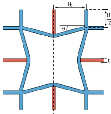
Figure 1-1 shows the main design used as a base for all meshes studied in the current work. The blue beams represent the material with the lower CTE and higher Young’s modulus, while the red beams correspond to the material with higher CTE and therefore, lower Young’s modulus, as for the above stated criteria based on [45]. Each mesh structure is characterized by being star-shaped and of re-entrant design, with the same repeating unit cell throughout the entire mesh. The unit cells are defined by four geometrical parameters that retain the same meaning in every mesh: three length parameters (H1 and
H2, and t, the latter simultaneously representing the beams’ thickness and width) and one angle
parameter (θ). The re-entrant geometry of the meshes, responsible for the auxetic behaviour, was left undisturbed.
Three main bi-dimensional meshes were designed, printed and tested. Their fabrication did not involve pins, adhesives, welding or pressure-fit joins. No alterations were done to the structures after their fabrication and they were tested as recovered from the printer. A commercially available 3-D printer has been used to print polymeric filaments, also available commercially. Combinations of four constituent materials were considered, copolyester (CPE+), Nylon, polypropylene (PP) and polyvinyl alcohol (PVA). The meshes were evaluated to determine their CTE and Poisson’s ratio.
To the author’s knowledge, the current work presents for the first time the production of a polymer-based composite mesh exhibiting anepectic behaviour, created from constituents with positive thermal expansion. These meshes may be applied to the Biomaterials field and shall be tuned to function at the working temperature range of the human body. From the current thesis resulted an article which has been submitted to “Smart Materials and Structures”.
t
Figure 1-1 Unit cell that is repeated for the entirety of the mesh. Variation of the four geometrical parameters offers the possibility to modify the geometry of the meshes.
5
2
2
M A T E R I A L S A N D
M E T H O D S
In this work, three main bi-dimensional polymeric meshes were designed, printed and tested. Comparative studies about each mesh were performed, regarding their CTE and Poisson’s ratio to understand the relation between each variable. The following sections describe in detail the characteristics of the meshes designed and examined, together with the methods used to test the filaments and the meshes.
2.1. Mesh Design
Figure 2-1 shows the five periodic mesh structures designed and studied. The meshes were modelled utilizing the 3-D modelling software 123D Design and were fabricated with a commercial
Ultimaker 3™ fused filament 3-D printing-system which utilized the temperature profiles provided
by Ultimaker. The cross-section of the beams is 1 mm 1mm thick for every main mesh design (mesh #1, mesh #2 and mesh #3) and of 0.5 mm 0.5 mm for the secondary meshes (mesh #2 50% and mesh #3 50%). Each mesh is symmetrical, and their geometrical parameters vary slightly form one mesh to the other, according to Table 2–1. The blue beams represent the material with the lower CTE and higher Young’s modulus, while the red beams correspond to the material with higher CTE and lower Young’s modulus.
Table 2–1 Parameters used in the design of the meshes. Parameters H1 (mm) H2 (mm) θ (º) t (mm) Mesh #1 10 10 15 1.0 Mesh #2 10 10 25 1.0 Mesh #2 50 % 5.0 5.0 25 0.5 Mesh #3 10 10 35 1.0 Mesh #3 50% 5.0 5.0 35 0.5
2.2. Printing equipment and filament characterization
The fabrication of the specimens is performed with a commercial Ultimaker 3™ fused filament 3-D printing-system, utilizing temperature profiles provided by Ultimaker. The materials used are commercially available Ultimaker™ filaments. Dogbone specimens for the mechanical characterization (elastic modulus) of 3-D printed samples of such materials were designed. All the specimens were printed horizontally, on the X-Y axis, directly on the heating plate without any supports. The filling density of the specimens was set to 100%, which means that all the specimens are solid structures.
(a) Mesh #1 (b) Mesh #2 (c) Mesh #2 50% (d) Mesh #3 (e) Mesh #3 50%
Figure 2-1 Five metamaterial meshes designed: (a) mesh #1, (b) mesh #2, (c) mesh obtained by scaling mesh #2 down by 50%, (d) mesh #3, (e) mesh obtain ed by scaling mesh #3 down by 50%. A common scale was used for all the above representations.
6
Tensile strength tests of different samples were carried out, the specimens were loaded to fracture (0.5 mm/min) by using a universal testing machine (AG-50kNG, Shimadzu, Japan).
The glass transition temperatures were obtained by differential scanning calorimetry (DSC 204 F1 Phoenix, Netzsch, Germany) extending from the temperature range of -50 to 250ºC at a rate of 3 K/min, with a protective atmosphere using nitrogen gas and cooled with liquid nitrogen.
The CTE of the materials was determined by thermo-mechanical analysis (TMA PT 1600, Linseis, Germany), the initial length of the specimens was of 10 mm and the analysis temperature range was from −10 ºC to 65 ºC at a rate of 1 K/min, with no protective atmosphere.
All of the polymers were tested on their CTE, and a portion, that showed promising results, were tested on their Young’s Modulus, and by differential scanning calorimetry.
2.3. Evaluation of thermo-mechanical characteristics of meshes
The fabrication of the meshes was performed with a commercial Ultimaker 3™ fused filament 3-D printing-system, with the ability to simultaneously process two different materials. Subsequent mesh testing was performed without the need for further finishing techniques, such as cleaning or polishing. For testing and analysis purposes small white marker dots were made on strategic locations on the mesh with white paint followed by a dot of black permanent marker in the centre of each white dot, as a way of contrast so as to appear clearer in the photographs.
The auxetic capabilities of the meshes were evaluated at room temperature, through a tensile effort applied to induce a constant elongation rate of 1 mm/s up to 10 mm overall elongation. Supplementary information concerning these tests is presented in section a. 1 of the Appendix, the resulting values being determined as explained in section a. 3 of the Appendix
To determine the CTE of the meshes, the set-up shown in Figure 2-2 was used. For the thermal experiment the mesh was contained between two parallel glass plates, to limit out-of-plane deformation, and submerged in silicone oil (Baysilone M350). It was then allowed to stabilise for 10 minutes, after which the silicone oil was heated, with the help of a hot plate, at a rate of 3 ºC/min, until a temperature of 85 ºC was reached. Some meshes were subject to consecutive heating and cooling cycles. In those cases, the CTE values were determined at the high temperature at the end of each cycle; the resulting overall permanent deformation, however, could only be measured at the end of the last cycle. CTE testing is explained in full detail in section a. 2 of the Appendix, the resulting values being determined as explained in section a. 3 of the Appendix.
In the next chapter, the relation between each mesh parameter and the expansion behaviour of the mesh when undergoing mechanical or thermal inputs will be discussed.
Silicone oil Gridded top glass
Metallic spacer Sample
Bottom glass plate Vat/container Hot plate Thermocouple
Figure 2-2 Schematic representation and description of the testing structure performed.
7
3
3 .
R E S U L T S A N D
D I S C U S S I O N
As discussed in the introduction, the constituent materials of the meshes must follow a specific criterion, the constituent materials must be of similar (albeit different) stiffness but widely differing thermal expansion. In order to attain anepectic behaviour the constituents must be studied in order to choose polymers which better suit the criteria.
The meshes were characterized on their CTE, and different mesh designs and mesh materials were used. By changing the materials (therefore changing the relation between the Young’s modulus and the CTE of the mesh constituents) as well as the geometrical parameters of the mesh, it is hypothesised that it is possible to tune the behaviour of the resulting structure in order to trigger the anepectic behaviour in a chosen range of temperatures.
3.1. Filament characterization
The materials used are commercially available Ultimaker™ polymer filaments. All were tested by thermos-mechanical analysis (TMA) for their CTE (see Figure a - 1 of the Appendix), some being also tested to determine their Young’s Modulus (see Figure a - 2 of the Appendix). Additionally, the materials were subjected to differential scanning calorimetry (see Figure a - 3 to Figure a - 6 of the Appendix) to establish their thermal stability. The complete set of results are listed in Table a - 1 of the Appendix. The materials which were ultimately chosen for the mesh fabrication were CPE+ (copolyester; black), Nylon (polyamide (grade based on PA6/PA66); black), PP (polypropylene; undyed) and PVA (polyvinyl alcohol compound; undyed). The two combinations selected for the current study were Nylon-PVA, and PP-CPE+, since their combination better suited the relation needed to achieve anepectic behaviour, of similar (albeit different) stiffness with widely differing thermal expansion, as shown in Figure a - 7 of the Appendix. The individual constituents of the meshes all have positive coefficients of thermal expansion. The values for the chosen materials are listed in Table 3–1.
Table 3–1 Material properties for CPE+, Nylon, PP and PVA. Material Young’s modulus
(GPa) CTE ( 10−6 ºC−1) Tg (ºC) CPE+ 1.031 71 105 Nylon 0.889 166 35 PP 0.152 248 -25 PVA 2.328 21 35
In possession of the data from Table 3–1, a set of sample meshes was selected for the study, as per Table 3–2, which summarizes the meshes studied. The material selection was performed within the constraints set by the available set of printable filaments. Mesh #2 50% was studied in two different material combinations on account of the larger number of unit cells simultaneously available for observation during characterization of the mesh behaviour.
As mentioned in the introduction, the constituent materials must be of similar stiffness but widely differing thermal expansion, which occurs on the combination Nylon-PVA and PP-CPE+. The Nylon-PVA pair has been chosen to comply with the previously mentioned criteria (stiffer and less thermally expansive blue struts vs. more flexible and more thermally expansive red struts), with
8
the PP-CPE+ pair standing for a similar situation, yet with a more dissimilar stiffness and a closer thermal expansion between the two materials (when compared to the Nylon-PVA relation, Figure a - 7 of the Appendix).
Table 3–2 Summary of meshes considered for the present work. , not tested. ✓, tested.
3.2. Auxetic behaviour
To confirm that the auxetic behaviour is indeed inherent to the mesh geometry, depending merely on the structure’s re-entrant architecture and not on the material or the materials combinations which constitute it, elongation tests were performed for some cases, the results being indicated in Table 3–3. During the tests, the selected meshes were imparted an overall elongation of 10 mm at room temperature, with a constant elongation rate of 1 mm/s.
Table 3–3 Poisson’s ratios for each mesh.
Mesh identification Poisson’s ratio ν
Mesh #2 Nylon −0.37
Mesh #2 Nylon-PVA −0.06
The tensile test results confirmed the auxetic nature of all meshes, regardless of being single- or dual-material; this was expected, since the auxetic behaviour rests essentially in the structure’s re-entrant geometry. The comparison between the values exhibited by the two #2 meshes seem attributable to the introduction, in the dual-material case, of a larger proportion of a more rigid material (PVA), which limits the extent of free deformation occurring along the transverse direction while the mesh is being forcefully deformed along the longitudinal direction.
Material
Mesh type
Mesh #1 Mesh #2 Mesh #2 50% Mesh #3 Mesh #3 50% Dual-material meshes Nylon-PVA
✓
✓
✓
✓
✓
PP-CPE+ ✓
Single-material meshes Nylon✓
✓
✓
✓
✓
PP ✓
9 3.3. Coefficient of thermal expansion
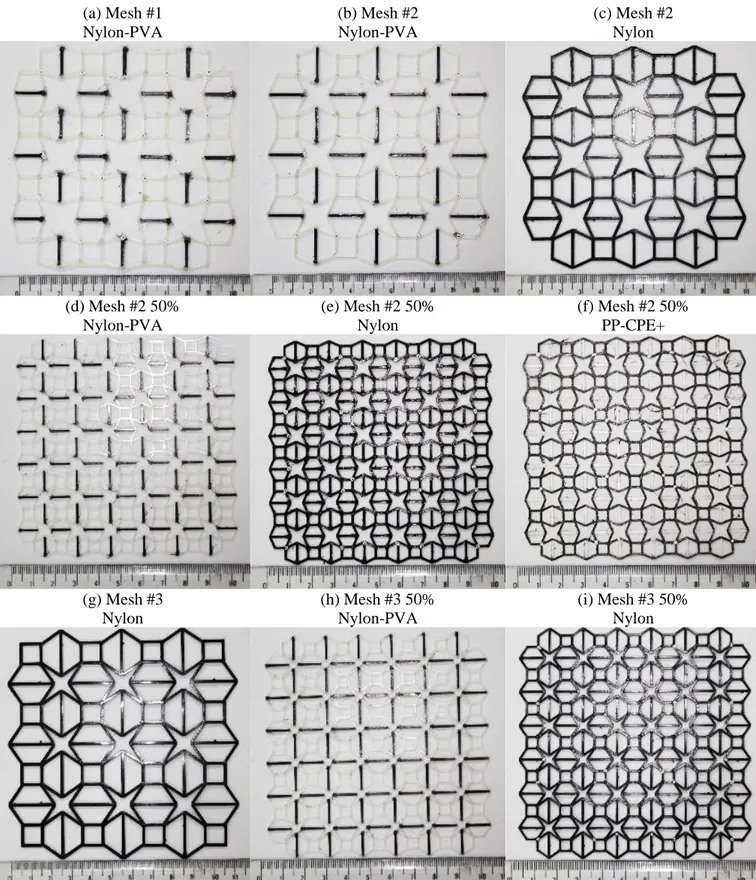
Figure 3-1 shows a portion of the meshes subjected to CTE testing. The full spectrum of meshes analysed include mesh #1, #2, #2 50%, #3 and #3 50%, in two dual-material combinations (Nylon-PVA and PP-CPE+) and in single-material meshes (Nylon and PP), in accordance with Table 3–2.
(a) Mesh #1 Nylon-PVA (b) Mesh #2 Nylon-PVA (c) Mesh #2 Nylon (d) Mesh #2 50% Nylon-PVA (e) Mesh #2 50% Nylon (f) Mesh #2 50% PP-CPE+ (g) Mesh #3 Nylon (h) Mesh #3 50% Nylon-PVA (i) Mesh #3 50% Nylon
Figure 3-1 Examples of the meshes tested in the present work. The mesh #2 50% in PP is omitted from this representation due to the transparent nature of the material, thus leading to a lack of contrast of the corresponding photographic record.
10 3.3.1. Effect of the out-of-plane motion
To determine the influence of the out-of-plane motion, the meshes displayed in Figure 3-1 (c, d and g) were tested. Figure 3-2 presents the measured CTE value for all the meshes considered, at 85 ºC. The results represented by plain-coloured columns in the figure correspond to tests performed without containment of the meshes. In such cases, the meshes were submerged in the oil and the upper glass plate (see detailed schematic of the experiment in Figure 2-2 and the fully detailed explanation in a. 2 of the Appendix) was omitted, the mesh therefore being allowed to deform in the Z direction. These results are compared to those concerning equal meshes tested according to the original constrained experiment configuration, with the meshes contained between two glass plates; the results from the constrained experiments are represented by the patterned columns in Figure 3-2 (b, d, f).
The results in Figure 3-2 (e and f) provide the first evidence of effective anepectic behaviour.
According to the data in Figure 3-2 (a) and (b), when testing mesh #2 made from a single-material, the CTE value is positive and comparable for both experiments (186 10−6 ºC−1 and 192 10−6 ºC−1). The observed difference corresponding to a 3% change for this case.
Similar results were achieved for the dual-material mesh #2 50% (Figure 3-2 (e) and (f)) and the single-material mesh #3 (Figure 3-2 (c) and (d)): comparing the results obtained in the unconstrained and constrained tests, the measured CTE maintained its sign, either negative or positive, respectively. The observed differences correspond to a 29% change for mesh #2 50% in Nylon-PVA, and 37% change for mesh #3 in Nylon.
Figure 3-2 CTE of mesh #2, #2 50% and #3 at 85 ºC, in the material combinations of Nylon-PVA and in the single-material mesh of Nylon. The patterned columns represent the meshes which were tested with contro l of the out-of-plane motion, this was achieved by placing the meshes between two stationary glass plates upon testing. The un -patterned columns represent the meshes tested without control of the mesh deformation in the Z direction, tested without the uppe r glass plate.
11 3.3.2. Effect of material combination
To elucidate how the different material combinations reacted to a temperature change, the meshes displayed in Figure 3-1 were tested. As previously mentioned, the different material combinations selected for this studied were chosen with reference to the criteria predicted by L. Ai
et al.[45], as most conducive to an effective NTE behaviour, combining a stiffer and less thermally
expansive material with another of more flexible and more thermally expansive behaviour.
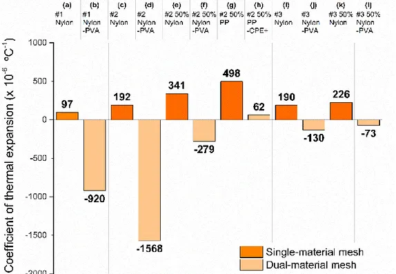
Figure 3-3 presents the measured CTE value for all the meshes considered, measured after heating from room temperature to 85 ºC. The results in Figure 3-3 (b), (d), (f), (j) and (l) provide evidence of effective anepectic behaviour. This result was never attained in any previous research, being the first non-virtual example of a polymer-based composite material exhibiting this type behaviour.
In order to ascertain whether the anepectic behaviour was indeed due to the nature of the dual-material combinations or if it simply resulted from geometric effects of the structures, there was a need to test the single-material version of the studied meshes, Figure 3-3 (a), (c), (e), (g), (i) and (k), and compare its behaviour with the corresponding dual-material.
According to the data in Figure 3-3 (a), when testing mesh #1 with a single-material CTE is positive (97 10−6 ºC−1), whereas when testing a dual-material mesh (in Nylon-PVA) the CTE becomes negative (−920 10−6 ºC−1), which confirms the previously reported observations.
Similarly, in Figure 3-3 (c), when testing mesh #2 with a single-material CTE is positive (192 10−6 ºC−1), whereas when testing a dual-material mesh (in Nylon-PVA) the CTE becomes negative (−1568 10−6 ºC−1), which confirms the previously reported observations. Similar results occurred with
mesh #2 50%: for Nylon the measured CTE (Figure 3-3 (e)) is positive (341 10−6 ºC−1) but becomes negative for the equivalent dual-material (Nylon-PVA) mesh (−279 10−6 ºC−1), showing that the anepectic behaviour is confined to the composite meshes. The results in Figure 3-3 (i), (j), (k) and (l) illustrate a similar effect, for mesh #3 and mesh #3 50%. When testing the single-material mesh #3
Figure 3-3 CTE of mesh #2, #2 50%, #3 and #3 50% at 85 ºC, in the material combinations of Nylon-PVA and PP-CPE+ and in the single-material mesh of Nylon and PP.
12
(in Nylon) the CTE is positive for both the full-size #3 mesh (190 10−6 ºC−1) and the halved, #3 50% mesh in Nylon (226 10−6 ºC−1) and negative for the equivalent dual-material (Nylon-PVA) mesh (−130 10−6 ºC−1 and −73 10−6 ºC−1, respectively). Consequently, when studying the
single-material versions of the aforementioned meshes the CTE values were all positive, and the equivalent dual-material meshes all reached negative CTE values, providing evidence of the success in fabricating anepectic dual-material meshes, from constituent materials with positive coefficients of thermal expansion.
By way of contrast, Figure 3-3 (g) shows, that testing mesh #2 50% with a single-material (in PP) the CTE was positive, at 498 10−6 ºC−1 but when testing the dual-material mesh (in PP-CPE+) the CTE remained positive, albeit with a smaller value of 62 10−6 ºC−1 (Figure 3-3 (h)), showing that the combination of PP-CPE+ did not succeed in having an anepectic behaviour, and as such wasn’t a combination worth pursuing for further testing.
This shows that the anepectic behaviour is only achieved through the adequate material combination in the designed mesh. The relation between the CTE and the Young’s modulus of the constituent materials in the composite mesh must be precise in order to result in the effective deformation of the more flexible constituent, by the stiffer constituent, when both dilate during heating, resulting in the overall mesh contraction by way of its particular geometry. For the case under analysis, while the stiffness ratios are similar (ENylon / EPVA = 0.38 vs. EPP / ECPE+ = 0.15) the
ratio of the CTE values is much larger (8.1) for the Nylon-PVA combination than for PP-CPE+ (for which it presents a value of 3.5). Thus, the requirement to anepectic behaviour seems to be that the combined materials exhibit similar (but different) stiffness but widely differing thermal expansion. Provided this requirement is respected, a choice of materials conducive to slight changes of the exact values of the stiffness and CTE ratios should allow fine tuning of the resulting anepectic behaviour.
3.3.3. Effect of mesh architecture
After ascertaining the importance of the adequate material combination to the emergence of the anepectic behaviour, the effectiveness of each geometry needed to be elucidated. This comparison is performed for meshes #1, # 2 and #3 in Nylon-PVA, the resulting CTE values being presented in Figure 3-4. A portion of meshes tested are displayed in Figure 3-1 (a) and (b).
Figure 3-4 CTE of mesh #1, #2 and #3 at 85 ºC, in the material combinations of Nylon-PVA.
13
As can be observed, all chosen dual-material meshes attained a negative coefficient of thermal expansion, mesh #2 being the extreme case, showing an extreme value of −1568 10−6 ºC−1 when the temperature varied between room temperature and 85 ºC, (Figure 3-4 (b)). In Figure 3-4 (a) mesh #1, in the same constituent materials, showed a CTE of −920 10-6 ºC-1. The same material
combination also displayed NTE with configuration in mesh #3, Figure 3-4 (c), with CTE showing a value of −130 10−6 ºC−1. Overall, the results in Figure 3-4 provide evidence of tuneable anepectic
behaviour through mesh design.
Furthermore, the results in Figure 3-4 show that, for the same material combination, a maximum value (in magnitude) of CTE is reached with mesh #2. The CTE value first decreases significantly with the increase of the angle θ, which changes from 15º in mesh #1 to 25º again increases mesh #2, (showed in Table 2–1), reaching an extreme value (in mesh #2), after which the CTE increases as θ progresses to 35º in mesh #3. This implies that an angle of 25º (or around this value) is more beneficial in attaining a more negative CTE, in agreement with predictions by L. Ai
et al. [45]. Once more, the observed behaviour reveals the possibility of tuning the magnitude of the
anepectic behaviour.
3.3.4. Effect of mesh scale
In order to identify how the anepectic effect is influenced by the mesh size, meshes #2 and #3, either single-material (Nylon) and dual-material (Nylon-PVA), were compared, in Figure 3-5, for both the full- and half-scale sizes.
Sensitivity differences between the two designs are already evident from the single-material meshes: while the CTE for #2 Nylon mesh changes from a full-size (Figure 3-5 (a)) 192 10−6 ºC−1 to a half-size (Figure 3-5 (c)) 341 10−6 ºC−1, which corresponds to a 78% change, for mesh #3 the
Figure 3-5 CTE of mesh #2, #2 50%, 33 and #3 50% at 85 ºC, in the material combinations of Nylon-PVA and in the single-material mesh of Nylon.
14
values are respectively 190 10−6 ºC−1 (full-size, Figure 3-5 (e)) and 226 10−6 ºC−1 (half-size, Figure 3-5 (g)), resulting in a 19% variation.
Such differences are exacerbated for the dual-meshes, where a size reduction of 50% led to negative CTE values for all dual-material meshes, although no generalized improvement could be observed: compared to the full size meshes, the size reduction led to a less markedly negative CTE. Again, this offers a different choice to fine-tune the anepectic behaviour. Peering over the CTE values measured for the different cases of Nylon-PVA meshes, one is also led to conclude that mesh #2, which at full-size scale (Figure 3-5 (b)) exhibits the highest magnitude negative CTE, at −1568 10−6 ºC−1, is the most sensitive to scale of the two geometries under comparison, CTE changing to −279 10−6 ºC−1 when the mesh is halved (Figure 3-5 (d)), corresponding to a 82% change. By
comparison, the relative change in CTE for mesh #3 is smaller, from a full-size mesh (Figure 3-5 (f)) −130 10−6 ºC−1 (result attained without out-of-plane control) to a half-sized mesh (Figure 3-5 (h))
−73 10−6 ºC−1, a 44% change.
The above observations show that a larger value of length parameter (for values around 10 mm for H1 andH2 and 1 mm for t, corresponding to the full size meshes) is more beneficial for
attaining a more negative CTE. The results in Figure 3-5, on the effect of scaling on a unit cell, provide evidence in achieving and tuning anepectic behaviour through mesh design.
3.3.5. Effect of plastic flow during heating
Mechanical properties of polymeric materials are highly sensitive to temperature; particularly above the glass transition temperature (Tg) all polymers will show plastic deformation. Therefore, the influence of this type of deformation on the response of the anepectic meshes must be clarified. For that purpose, two different material combinations were tested, using half-size mesh #2. Whilst the Nylon-PVA pair was chosen due to having close Tg values, PP-CPE+ was selected because the two materials exhibit widely differing Tg values, as shown in Table 3–1 above. For the sake of
Figure 3-6 CTE of mesh #2 50% from the variation of 27 ºC until 120 ºC, in the single-material mesh of PP (a) and in the material combination of PP-CPE+ (b) and Nylon-PVA (c).
15
comparison, the single-material case, based on PP, was also tested. The CTE values for these meshes are presented in Figure 3-6.
The observation of these results firstly confirms that, irrespective of being below or above Tg, single-material meshes never exhibit anepectic behaviour. On the other hand, for the dual-material cases, anepectic behaviour only manifests itself above the Tg level of both constituents.
After completing the tests above, the meshes were examined and found to have undergone plastic deformation, due to the polymer flow occurring above Tg. This prompted the execution of
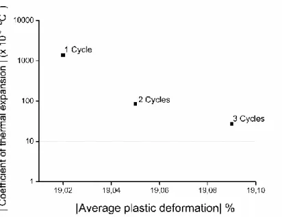
sequential heating and cooling tests, which were performed on mesh #2 50% in Nylon-PVA, to elucidate the effect on the anepectic behaviour of the plastic deformation of the elementary struts; the relevant results are shown in Figure 3-7.
The trend exhibited by the results shows that the anepectic effect becomes progressively less pronounced, probably due to the accumulation of irreversible deformation. This effect is most noticeable already after the first heating and cooling sequence, so that when the mesh undergoes subsequent heating the anepectic behaviour becomes negligible.
Ultimately the anepectic effect and its possible tuneability stems from an adequate design of the mesh, accurate selection and combination of material and the synergy of the plastic flow of the constituents occurring above Tg, which will bring about the desired designed deformation.
Figure 3-7 Variation of the measured value of the coefficient of thermal expansion for the Nylon -PVA #2 50% mesh, as the plastic deformation increases during consecutive heating and cooling cycles; the initial dimensions of the mesh (before heating) were taken as reference for the calculation of the avera ge plastic deformation.
17
4
4
C O N C L U S I O N S A N D
F U T U R E P E R S P E C T I V E S
A series of polymeric metamaterials with tuneable mechanical properties were designed, using star-shaped re-entrant bi-dimensional structures, utilizing constituents with positive thermal expansion, and were subsequently fabricated with a 3-D printing system, being tested so as to simultaneously display negative values of Poisson ratio and CTE, configuring an anepectic behaviour. Thus, to the author’s knowledge, the present work provides the first non-virtual example of a polymer-based composite material exhibiting anepectic behaviour. As such, an article on the current thesis has been submitted to “Smart Materials and Structures”.
Design variables for each mesh consisted of constituent materials properties and combinations, three different length parameters and one angular parameter. The effects of these geometrical parameters and material combinations on the CTE and Poisson’s ratio were studied through a series of room temperature active deformation and controlled heating passive deformation tests.
The anepectic behaviour could only be observed when the combined materials presented similar, yet different, stiffness values, together with widely different intrinsic CTE, the stiffer and less thermally expansive material forming a continuous re-entrant network, with connecting struts between contiguous stars made from the second material. Provided this requirement is respected, a choice of materials conducive to slight changes of the exact values of the stiffness and CTE ratios should allow fine tuning of the resulting anepectic behaviour. Furthermore, the anepectic behaviour was only observed above the glass transition temperature of both constituent materials. Due to the irreversible nature of the deformation occurring at such temperature ranges, when subjected to consecutive heating and cooling cycles, the anepectic effect displayed by the meshes became progressively less pronounced.
Geometry-wise, the observed CTE showed a marked dependence on the angular parameter, attaining a more negative value for an intermediate angle around 25º. Concerning the length parameters, the CTE became more negative for larger sized meshes. Future studies must optimize the mesh design. Regarding the length parameters, different values of H1 and H2 must be studied
(as this thesis focused on equal length values of H1 and H2) a value of H2 smaller by approximately
15 mm than H1 should be studied [45]. Several θ angular values, of around 25º, must also be
studied. Considering that when H2 is larger than H1 the main influence on the exhibited CTE is
due to the angle θ, whereas if H2 is smaller than H1 then it is H2 that most influences the mesh’s
CTE [45], the H1/H2 ratio deserves further investigation. Finally, changing parameter values may
not lead to a linear change of CTE, as the ratios and relations between each parameter must be considered and a full parametric study on the relation that each parameter maintains with every other parameter should be developed. Considering that when H2 is larger than H1 the main
influence on the exhibited CTE is due to the angle θ, whereas if H2 is smaller than H1 then it is
H2 that most influences the mesh’s CTE [45], the H1/H2 ratio deserves further investigation.
Finally, changing parameter values may not lead to a linear change of CTE, as the ratios and relations between each parameter must be considered and a full parametric study on the relation that each parameter maintains with every other parameter should be developed.
Ultimately the anepectic effect and the possibility for fine tuning stems from an adequate design of the mesh, accurate selection and combination of materials and the synergy of the plastic flow of the constituents occurring above Tg, which will bring about the desired designed deformation. To understand if the anepectic effect could be achieved without plastic flow of the
18
constituent materials, a future work should be developed, studying and utilizing different combinations of constituent materials with different Tg temperatures; if feasible, and maintaining biomedical applications in mind, such studies should focus on polymers which possess a glass transition temperature higher than 40 ºC. Therefore, future meshes should manifest their anepectic behaviour below the Tg of the constituents (proving that the effect does not rely upon the plastic flow of the constituents) and more, work in the temperature range of the human body (allowing them to be applied as devices in the Biomaterial field).
Regarding currently printable, filament-ready polymers, materials such as polyamides, ionomers [49] (thermoplastic) and cellulose polymers [50], fulfil the request of 40 ºC for Tg and current commercial availability (see Figure 4-1). Apart from adequate Tg, the selectable materials must also interact with each other in a synchronized combination that respects the base criteria (a combination of polymers with similar (albeit different) stiffness and widely differing thermal expansion). By way of illustration, several types of polyamides are currently available commercially, manufacturers offer slightly different variations of filament with slightly different material composition, as each chooses to stabilize and extrude their filament differently; therefore, not all 3-D printing polyamides possess the same mechanical and thermal properties.
Design and optimization of anepectic structures, with appropriately selected geometrical parameters and material combination, deserve further investigation. The models, materials and printing technology are expected to evolve further, and a great deal of work and research needs to be done by the scientific community on this matter. This work should open a path into further studies concerning polymer-based anepectic structures, mainly for the biomedical field, but the creation of metallic anepectic structures, e.g. for the aerospace and defence industry, also becomes a foreseeable prospect.
Figure 4-1 CTE-Young’s Modulus map of known materials. Represented in the solid gre en colours are the polymers which, according to the program (CES Edupack 2015), can currently be used to fabricate products via addictive manufacturing methods:
By deposition techniques: ionomer, polyethylene terephthalate (PET), polyvinylchloride (tpPVC), PLA, polyetheretherketone (PEEK), Nylons, PC, cellulose polymers (CA), polyurethane (tpPUR) and ABS.
By laser-based techniques: polytetrafluoroenthylene (PTFE), polystyrene (PS), polymethyl methacrylate (PMMA) and epoxies.
Not all 3-D printable polymers are represented in the graph, due to the constant developments in materials engineering.
19
1 0
R E F E R E N C E S
[1] J. N. Grima, P.-S. Farrugia, R. Gatt, and V. Zammit, “Connected Triangles Exhibiting Negative Poisson’s Ratios and Negative Thermal Expansion,” J. Phys. Soc. Japan, vol. 76, no. 2, p. 025001, Feb. 2007.
[2] C. S. Ha, E. Hestekin, J. Li, M. E. Plesha, and R. Lakes, “Controllable thermal expansion of large magnitude in chiral negative Poisson’s ratio lattices,” Phys. status solidi, vol. 252, no. 7, pp. 1431–1434, Jul. 2015.
[3] X. Ren, J. Shen, A. Ghaedizadeh, H. Tian, and Y. Min Xie, “Experiments and parametric studies on 3D metallic auxetic metamaterials with tuneable mechanical properties,” Smart
Mater. Struct., vol. 24, no. 9, p. 095016, Sep. 2015.
[4] A. Versluis, W. H. Douglas, and R. L. Sakaguchi, “Thermal expansion coefficient of dental composites measured with strain gauges,” Dent. Mater., vol. 12, no. 5, pp. 290– 294, 1996.
[5] A. W. Sleight, “Negative thermal expansion materials,” Curr. Opin. Solid State Mater.
Sci., vol. 3, no. 2, pp. 128–131, Apr. 1998.
[6] N. Yamamoto, E. Gdoutos, R. Toda, V. White, H. Manohara, and C. Daraio, “Thin Films with Ultra-low Thermal Expansion,” Adv. Mater., vol. 26, no. 19, pp. 3076–3080, May 2014.
[7] Y. C. Fung, Foundations of Solid Mechanics. Englewood Cliffs, Prentice-Hall, 1965. [8] K. E. Evans and A. Alderson, “Auxetic Materials: Functional Materials and Structures
from Lateral Thinking!,” Adv. Mater., vol. 12, no. 9, pp. 617–628, May 2000.
[9] K. Takenaka, “Negative thermal expansion materials: technological key for control of thermal expansion,” Sci. Technol. Adv. Mater., vol. 13, no. 1, p. 013001, Feb. 2012. [10] G. D. Barrera, J. A. O. Bruno, T. H. K. Barron, and N. L. Allan, “Negative thermal
expansion,” J. Phys. Condens. Matter, vol. 17, no. 4, pp. R217–R252, Feb. 2005.
[11] W. Miller, C. W. Smith, D. S. Mackenzie, and K. E. Evans, “Negative thermal expansion: a review,” J. Mater. Sci., vol. 44, no. 20, pp. 5441–5451, Oct. 2009.
[12] C. Closmann, A. W. Sleight, and J. C. Haygarth, “Low-Temperature Synthesis of ZrW2O8and Mo-Substituted ZrW2O8,” J. Solid State Chem., vol. 139, no. 2, pp. 424– 426, Sep. 1998.
[13] W. J. Clegg and A. Kelly, “Choosing Materials for Composites with a Greater Range of Properties,” Adv. Eng. Mater., vol. 4, no. 6, pp. 388–392, Jun. 2002.
[14] Q. Wang, J. A. Jackson, Q. Ge, J. B. Hopkins, C. M. Spadaccini, and N. X. Fang, “Lightweight Mechanical Metamaterials with Tunable Negative Thermal Expansion,”
Phys. Rev. Lett., vol. 117, no. 17, p. 175901, Oct. 2016.
[15] R. Lakes, “Foam Structures with a Negative Poisson’s Ratio,” Science (80-. )., vol. 235, no. 4792, pp. 1038–1040, Feb. 1987.
20
[16] K. E. Evans, M. A. Nkansah, I. J. Hutchinson, and S. C. Rogers, “Molecular network design,” Nature, vol. 353, p. 124, Sep. 1991.
[17] Terry Wohlers and T. Gornet, “History of Additive Manufacturing, Introduction of non-SL systems Introduction of low-cost 3D printers,” 2014, pp. 1–24.
[18] M. H. Fu, O. T. Xu, L. L. Hu, and T. X. Yu, “Nonlinear shear modulus of re-entrant hexagonal honeycombs under large deformation,” Int. J. Solids Struct., vol. 80, pp. 284– 296, Feb. 2016.
[19] C. Huang and L. Chen, “Negative Poisson’s Ratio in Modern Functional Materials,” Adv.
Mater., vol. 28, no. 37, pp. 8079–8096, Oct. 2016.
[20] R. Lakes, Roderic SLakes, “Negative-Poisson’s-Ratio Materials: Auxetic Solids,” Annu.
Rev. Mater. Res., vol. 47, no. 1, pp. 63–81, Jul. 2017.
[21] M. Shokri Rad, Y. Prawoto, and Z. Ahmad, “Analytical solution and finite element approach to the 3D re-entrant structures of auxetic materials,” Mech. Mater., vol. 74, pp. 76–87, Jul. 2014.
[22] K. K. Saxena, R. Das, and E. P. Calius, “Three Decades of Auxetics Research − Materials with Negative Poisson’s Ratio: A Review,” Adv. Eng. Mater., vol. 18, no. 11, pp. 1847– 1870, Nov. 2016.
[23] X.-T. Wang, B. Wang, X.-W. Li, and L. Ma, “Mechanical properties of 3D re-entrant auxetic cellular structures,” Int. J. Mech. Sci., vol. 131–132, no. March, pp. 396–407, Oct. 2017.
[24] M. Schenk and S. D. Guest, “Geometry of Miura-folded metamaterials,” Proc. Natl. Acad.
Sci., vol. 110, no. 9, pp. 3276–3281, Feb. 2013.
[25] S. Babaee, J. Shim, J. C. Weaver, E. R. Chen, N. Patel, and K. Bertoldi, “3D Soft Metamaterials with Negative Poisson’s Ratio,” Adv. Mater., vol. 25, no. 36, pp. 5044– 5049, Sep. 2013.
[26] O. Bouaziz, J. P. Masse, S. Allain, L. Orgéas, and P. Latil, “Compression of crumpled aluminum thin foils and comparison with other cellular materials,” Mater. Sci. Eng. A, vol. 570, pp. 1–7, May 2013.
[27] C. S. Ha, M. E. Plesha, and R. Lakes, “Chiral three-dimensional isotropic lattices with negative Poisson’s ratio,” Phys. status solidi, vol. 253, no. 7, pp. 1243–1251, Jul. 2016. [28] D. Rodney, B. Gadot, O. R. Martinez, S. R. du Roscoat, and L. Orgéas, “Reversible
dilatancy in entangled single-wire materials,” Nat. Mater., vol. 15, no. 1, pp. 72–77, Jan. 2016.
[29] G. Carta, M. Brun, and A. Baldi, “Design of a porous material with isotropic negative Poisson’s ratio,” Mech. Mater., vol. 97, pp. 67–75, Jun. 2016.
[30] K. Wang, Y.-H. Chang, Y. Chen, C. Zhang, and B. Wang, “Designable dual-material auxetic metamaterials using three-dimensional printing,” Mater. Des., vol. 67, pp. 159– 164, Feb. 2015.
[31] L. Wu, B. Li, and J. Zhou, “Isotropic Negative Thermal Expansion Metamaterials,” ACS
Appl. Mater. Interfaces, vol. 8, no. 27, pp. 17721–17727, Jul. 2016.