Introduction
Tissue engineering (TE) is an interdisciplinary
field that employs a combination of cells, scaffolds and stimuli to repair damaged tissues or organs. Scaffolds are supposed to act as a temporary artificial extracellular matrix (ECM), providing initial support for cells, which must adhere and proliferate three-dimensionally. In this context, fibrous scaffolds have caught researchers’ attention because of their microstructural similarity to the native ECM (Barnes et al., 2007).
Solution blow spinning (SBS) has been studied as an accessible and versatile alternative to electrospinning
(currently, the most commonly adopted technique). It consists of a spraying apparatus with concentric nozzles, where a polymer jet is accelerated using a stream of compressed gas. A syringe pump controls the injection rate, and the pressure is adjusted with a cylinder pressure regulator/air compressor. The fibers are extruded as the solvent evaporates, and are deposited on a target, which can be made of several types of material, not necessarily metallic. SBS is not a brand-new technique, but it was adapted for drug delivery purposes by Medeiros et al. in 2009, and it has been also used in the field of TE by other research groups ever since
(Medeiros et al., 2009; Tutak et al., 2013).
A couple of years after Medeiros’s publication, Srinivasan et al. (2011) stated that it would also be possible to use a commercial airbrush designed for painting (instead of the specifically built nozzle coupled to a syringe pump) with a pressurized nitrogen stream to create bundled fibers. In this case, the solution is fed gravitationally, therefore, the rate cannot be controlled, but the advantage is that the equipment is readily available.
In comparison to electrospinning, both techniques are considered: (1) safer for not employing high voltage; (2) more versatile because the collector does not need to be electrically conductive; (3) more productive, due
Production of fibrous polymer scaffolds for tissue engineering using
an automated solution blow spinning system
Alessandra Forgatti Hell
1*, Márcia Mayumi Omi Simbara
2, Paulo Rodrigues
1, Danilo Akio Kakazu
1,
Sônia Maria Malmonge
11 Center for Engineering, Modeling and Applied Social Sciences, Federal University of ABC, São Bernardo do Campo, SP, Brazil. 2 Center for Engineering in Circulatory Assistance, Dante Pazzanese Institute of Cardiology, São Paulo, SP, Brazil.
Abstract Introduction: Solution blow spinning (SBS) and airbrushing are two techniques that can be used as alternatives to electrospinning in the production of fibrous scaffolds for tissue engineering (TE). SBS seems particularly interesting due to its versatility, however, it has not been much explored and no automated SBS systems were found in the literature. Therefore, the present work aimed to develop such equipment and compare the results to those found for airbrushing, considering the same set of parameters. Methods: A new SBS set up, composed of a specially designed nozzle with automated movement, a syringe pump and a compressor, was used to produce fibrous poly (ε-caprolactone) (PCL) mats. The airbrushed fibers were produced under the same conditions, and samples of both types of mats were imaged using scanning electron microscopy (SEM) to compare them in terms of microstructure and fiber diameter. Results: The SBS system was robust and performed well, in terms of movement and fiber deposition. In comparison to airbrushing’s, SBS mats presented different microstructural characteristics (considering the parameters used). Conclusion: The biggest advantage over airbrushing may be its versatility and simple automation, which may improve sample reproducibility, especially considering scaled up processes. To further improve this apparatus, a better understanding of how process variables interfere in the microstructure is needed, as well as more sophisticated interface and operation.
Keywords Fibrous scaffolds, Solution blow spinning, Airbrushing.
This is an Open Access article distributed under the terms of the Creative Commons Attribution License, which permits unrestricted use, distribution, and reproduction in any medium, provided the original work is properly cited.
How to cite this article: Hell AF, Simbara MMO, Rodrigues P,
Kakazu DA, Malmonge SM. Production of fibrous polymer scaffolds for tissue engineering using an automated solution blow spinning system. Res Biomed Eng. 2018; 34(3):273-278. DOI: 10.1590/2446-4740.180039.
*Corresponding author: Alessandra Forgatti Hell, Center for
Engineering, Modeling and Applied Social Sciences, Universidade Federal do ABC, Alameda da Universidade, s/n, Bairro Anchieta, CEP 09606-045, São Bernardo do Campo, SP, Brazil. E-mail: [email protected]
to the high flow rate that can be used; and (4) useful to cover molds of complex shapes, because it can “paint” fibers over different geometries. Another important point is that they can be easily implemented, using a low cost, user-friendly equipment, which can also be portable
(Daristotle et al., 2016; Tutak et al., 2013).
Despite SBS’s potential, it has not been much explored research-wise. Also, automated SBS systems, which would ensure greater reproducibility of the results, were not found in the literature until the present moment. Considering this, the present work aimed to develop a semi-automatic SBS system to produce fibrous scaffolds for TE, using basic engineering concepts and widely available materials, and compare its pros and cons to the airbrushing technique.
Methods
In this work, only the nozzle and the device for its fixation and movement were developed. The other items of the system were commercially acquired: a syringe pump (BSV 700 FlexPump – Biosensor, Brazil) for flow control of polymer solution, and a compressor (Super 50 – Fiac, Brazil) for air supply.
SBS Semi-automated System
Nozzle
To allow a more versatile application (in terms of parameter variation) and equipment durability, some features were introduced. Firstly, the nozzle was designed to allow an easy disassembly for cleaning and needle exchanging, as well as the variation of the protrusion distance. Also, it is possible to change the tip of the nozzle, which enables the use of different geometries. The body of the nozzle is made of aluminum (for its lightness), and the internal parts are made of stainless steel AISI 306, because of its resistance to solvent attack (present in the solution).
Nozzle movement
The controlled movement is based on the principle of Computer Aided Manufacturing (CAM). The nozzle can move in two directions (horizontal and vertical), and this movement is performed by step motors (Akiyama NEMA 17 – Grupo Neoyama, Brazil) controlled by an Arduino® Uno R3 board through Arduino IDE’s (Integrated Development Environment) Serial Monitor. After an initial calibration with ultrasonic sensors (HC-SR04), it is possible to select motor speed, range of movement in both directions and the number of time it repeats the command.
Collector
The collector, which can be made of any material and shape, is fixed to a carriage, guided in the longitudinal direction to the nozzle. To maintain a constant working distance, there is a millimeter measuring stainless steel ruler that serves as reference, and there is also a positioning lock.
Structure
All components are fixed to structural profiles of extruded aluminum using specifically designed parts. These pieces were manufactured with a 3D MovtecH Cúbica printer (MovtecH, Brazil) using ABS (acrylonitrile butadiene styrene) as printing material. If necessary, other elements can be incorporated later.
Figure 1 shows the entire assembled system, with a detailed view of the nozzle and provides a closer look at the polymer jet being streamed towards the collector.
Sample preparation
Polymer solution
A solution of 4% w/v of poly(ε-caprolactone) (PCL) (Mn 80000 - Sigma Aldrich, USA) in chloroform (Synth, Brazil) was prepared for both techniques.
Solution blow spun fibers
The nozzle was connected to the air compressor and to the syringe pump, where the solution had been inserted. The parameters used in the process were: flow rate of 30 µL/min, distance from nozzle to collector of 10 cm, and pressure of 30 psi. The movement was assessed, but for the fabrication of the mats, it was chosen to keep a static fiber deposition, to narrow down the system variables and allow a better comparison to the airbrushing technique.
Airbrushed fibers
The airbrush was coupled to the air compressor, and the solution was poured into the reservoir. Apart from the flow rate, the same parameters were used.
Mat analyses
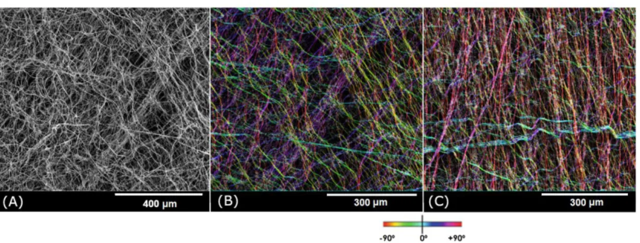
SBS and airbrushing samples were gold coated with a sputtering system (EM ACE200 - Leica Microsystems, Germany) and then imaged using scanning electron microscopy (SEM) (Quanta 250 – FEI, USA). Fiber diameter was manually measured using ImageJ (n = 50 fibers per image, 3 images for each fabrication technique). Two SBS images were processed via ImageJ’s plugin OrientationJ for qualitative fiber orientation analysis
Results
SBS system
The initial tests with the complete SBS system (including the movement) were satisfactory. The motors performed the commands and the programmed movements accurately, repeated times, in both directions.
The nozzle worked as expected and produced fibrous mats, as shown in Figure 2A. Interestingly, after processing the SEM images with OrientationJ
(Figures 2B and 2C), it was possible to observe that
fibers in the areas closest to the borders of the mats are more aligned, due to the air pressure. The color map indicates the angle of the fiber.
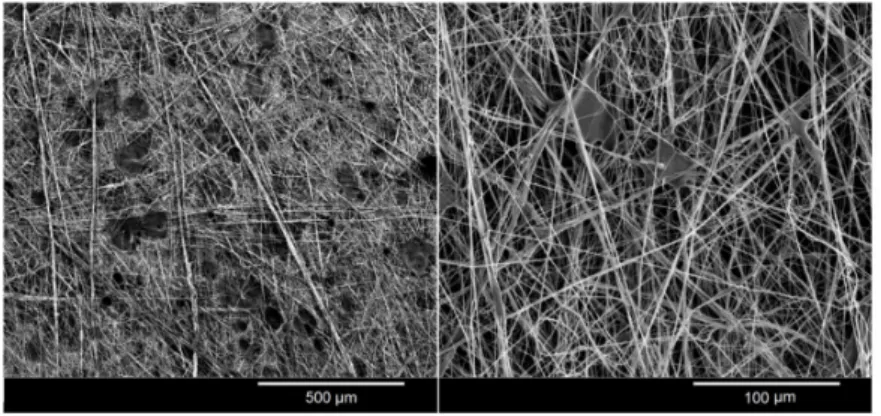
Nevertheless, system malfunctioning sometimes hindered fiber deposition, which resulted in either holes or dense regions among fibers (Figure 3).
SBS x Airbrushing
Mats produced with both techniques are very similar, have a whitish color and even with the naked eye it is possible to see that they are fibrous (Figure 4).
Figure 1. (A) Photograph of the semi-automatic solution blow spinning system, (B) detailed view of the nozzle project, and (C) photograph of the polymer jet leaving the nozzle.
Their microstructure (Figure 5A) is also very similar, but there is one difference that can be noted: for this particular set of parameters, airbrushing seems to produce more beads and fiber bundles than SBS.
Fiber diameter range was practically the same for both: 132-1607 nm for airbrushing, and 132-1268 nm for SBS, however, their distribution is slightly different
(Figure 5B).
Figure 3. Scanning electron microscopy images of defects from solution blow spun samples.
Figure 4. Fiber mats of 4% w/v poly(ε-caprolactone) in chloroform obtained by (A) airbrushing and (B) solution blow spinning.
The main characteristics of the two systems here described are shown in Table 1. While both can be used for the same purpose, there are some differences that should be noted. Airbrushing presents as advantages the lower cost and immediate availability; however, there are fewer parameters that can be adjusted, what could imply that it is less versatile and less reproducible (especially considering flow rate control).
Discussion
The automated SBS system proved to be capable of producing micro and nanofibers while remaining relatively simple and easily replicated. In the literature, fibrous PCL scaffolds produced with commercial airbrushes have already shown a favorable biological response, which leads to believe the samples obtained in the present work are also promising for TE (Tutak et al., 2013).
Even though most of the attempts were successful, system malfunctioning occasionally occurred and resulted in microstructural defects in the mats. Nozzle clogging caused either a reverse flow of the solution to the syringe pump or an irregular solution discharge towards the collector, and in this case, the solvent would not completely evaporate in its trajectory and would create dense regions and/or dissolve the fibers already deposited in the samples. Finding an optimal feed rate should avoid, or at least reduce, the occurrence of such events.
When it comes to the comparison of SBS with airbrushing, these two techniques share the same overall characteristics, but it is not possible to directly extrapolate a set of parameters (solution concentration, pressure, etc.…) from one to the other and expect the same results. They may eventually generate almost identical microstructural features, but under different conditions. For the set of parameters used in this work, airbrushing tended to generate more fiber bundles than
SBS, and produced more beads as well. This is neither good nor bad, considering there is a more appropriate morphology for each application, but it will definitely influence the scaffold’s mechanical properties.
In terms of fiber diameter, it is normally recommended that scaffolds’ fibers should be of the same magnitude (in diameter) of native structural ECM proteins (50-500 nm), and, in this case, both techniques partially satisfy that requirement, considering that most (but not all) diameters fall within that criteria. Airbrushing’s high outlier (1600-1800 nm) could possibly represent a bundle of two or more fibers that were so closely packed that looked as if they were a single fiber. Diameter ranges were similar, but airbrushing showed a narrower distribution than SBS, which could indicate a more controlled fiber deposition, at least for this set of parameters. It is possible that by adjusting SBS’s feed rate to an optimal value a reduced fiber diameter and narrower distribution could be obtained, as previously observed by Oliveira et al. (2011).
Considering all the other pros and cons of the two techniques too, airbrushing seems to be a great starting point, where one can learn a lot without spending much. However, when possible, it is advisable to optimize the system and improve its reproducibility, especially considering scaled up processes and clinical viability. Evidently, a commercial airbrush could well be adapted to achieve a controlled feed and automated trigger, but then the advantage of being readily available is simply lost. Other than that, investigating how different nozzle geometries affect the scaffold’s microstructure could help advance research in the field.
In future studies, it is essential to thoroughly assess the influence of system variables (pressure, feed rate, distance from nozzle to collector and nozzle geometry), of environmental conditions (temperature and humidity), and of the polymer solution (concentration and different solvents) on the resulting microstructure to then optimize
Table 1. Comparative summary of the data found for airbrushing and solution blow spinning in the present study.
Technique Airbrushing Solution blow spinning
Cost* (US$) Airbrush starts at US$ 25 US$ 260 nozzle, US$ 690 syringe pump
System variables Pressure
Distance from nozzle to collector Needle diameter
Pressure
Distance from nozzle to collector Needle diameter
Flow rate Nozzle design
Microstructure Fibers, bundles and beads Fibers and few bundles
Fiber diameter 132-1607nm 132-1268 nm
Availability Immediate – commercially available Project + Manufacturing
Transport Hand-held Hand-held, however the syringe pump must also
be transported
Assembly Simple Simple
the process. Regarding the automation, there are also improvements to be made, which include different nozzle trajectories, a rotary collector to allow fiber alignment, and a dedicated equipment to operate the system without the need of a computer.
Acknowledgements
The authors are grateful to the National Council for the Improvement of Higher Education (CAPES), the National Council for Scientific and Technological Development (CNPq) (process no. 402984/2016-1) and the Federal University of ABC (UFABC) for their financial support, and the Multiuser Central Facilities (UFABC) for the experimental support.
References
Barnes CP, Sell SA, Boland ED, Simpson DG, Bowlin GL. Nanofiber technology: designing the next generation of tissue engineering scaffolds. Adv Drug Deliv Rev. 2007; 59(14):1413-33. http://dx.doi.org/10.1016/j.addr.2007.04.022. PMid:17916396. Daristotle JL, Behrens AM, Sandler AD, Kofinas P. A review of the fundamental principles and applications of solution blow spinning. ACS Appl Mater Interfaces. 2016; 8(51):34951-63. http://dx.doi.org/10.1021/acsami.6b12994. PMid:27966857. Medeiros ES, Glenn GM, Klamczynski AP, Orts WJ, Mattoso LHC. Solution blow spinning: a new method to produce micro-
and nanofibers from polymer solutions. J Appl Polym Sci. 2009; 113(4):2322-30. http://dx.doi.org/10.1002/app.30275. Oliveira JE, Moraes EA, Costa RGF, Afonso AS, Mattoso LHC, Orts WJ, Medeiros ES. Nano and submicrometric fibers of poly(d,l-lactide) obtained by solution blow spinning: process and solution variables. J Appl Polym Sci. 2011; 122(5):3396-405. http://dx.doi.org/10.1002/app.34410.
Püspöki Z, Storath M, Sage D, Unser M. Transforms and operators for directional bioimage analysys: A survey. In: De Vos WH, Munck S, Timmermans J-P, editors. Advances in anatomy, embryology and cell biology: focus on bio-image informatics. Switzerland: Springer International Publishing; 2016. p. 69-93. http://dx.doi.org/10.1007/978-3-319-28549-8_3. Rezakhaniha R, Agianniotis A, Schrauwen JTC, Griffa A, Sage D, Bouten CVC, van de Vosse FN, Unser M, Stergiopulos N. Experimental investigation of collagen waviness and orientation in the arterial adventitia using confocal laser scanning microscopy. Biomech Model Mechanobiol. 2012; 11(3-4):461-73. http:// dx.doi.org/10.1007/s10237-011-0325-z. PMid:21744269. Srinivasan S, Chhatre SS, Mabry JM, Cohen RE, McKinley GH. Solution spraying of poly(methyl methacrylate) blends to fabricate microtextured, superoleophobic surfaces. Polymer (Guildf). 2011; 52(14):3209-18. http://dx.doi.org/10.1016/j. polymer.2011.05.008.