Dmytro Snisarenko
Graduated in
Preparation and characterization of
microfiltration flat polymeric membranes
for biomedical applications
Dissertation for obtaining the Master degree in Membrane Engineering
Erasmus Mundus Master in Membrane Engineering
Advisor: Luca Querze, New Product & Technology Manager,
GVS Filter Technology
Co-advisor(s): Isabel Coelhoso, Professor, FCT-UNL
João G. Crespo, Professor, FCT-UNL
Jury:
President: Isabel Coelhoso, Professor, FCT-UNL Examiners: Carla Portugal, Professor, FCT-UNL
Karel Bouzek, Professor, ICTP Patrice Bacchin, Professor, UPS
André Ayral, Professor, UMII
Members: Luca Querze, GVS Filter Technology
Dmytro Snisarenko
Graduated in
Preparation and characterization of
microfiltration flat polymeric
membranes for biomedical
applications
Dissertation presented to Faculdade de Ciências e Tecnologia, Universidade Nova de Lisboa for obtaining the master degree in Membrane Engineering
Preparation and characterization of microfiltration flat polymeric membranes for biomedical applications
The EM3E Master is an Education Programme supported by the European Commission, the European Membrane Society (EMS), the European Membrane House (EMH), and a large
international network of industrial companies, research centres and universities
(http://www.em3e.eu).
Copyright @ Name, FCT/UNL
A Faculdade de Ciências e Tecnologia e a Universidade Nova de Lisboa têm o direito, perpétuo e sem limites geográficos, de arquivar e publicar esta dissertação através de exemplares impressos reproduzidos em papel ou de forma digital, ou por qualquer outro meio conhecido ou que venha a ser inventado, e de a divulgar através de repositórios científicos e de admitir a sua cópia e distribuição com objectivos educacionais ou de investigação, não comerciais, desde que seja dado crédito ao autor e editor.
Acknowledgments
I would like to express my gratitude to Mr. Luca Querze and Mr. Davide Rinaldi for the useful comments, remarks and engagement through the whole process of this master thesis preparation.
Furthermore I would like to thank the services and help from Alessia Campisi working in HR department.
Additionally I want to mention the contribution of Ing. Nino Gaeta in the organization of my stay in GVS Filter Technology.
My deep appreciation also goes to all members of the membrane research group (Fausto Lentini, Felice Sidari, Elsa Caruso) for their advice and assistance.
I would like to thank Weibing Feng for SEM analysis and permporometry tests.
I would like to thank the examination committee for their advices and comments on my thesis.
I would like to thank all my best friends for their support and encouragement.
Abstract
The optimal methodology for flat supported hydrophobic microporous poly(vinylidene) fluoride (PVDF) industrial membranes (Fortex 0.1, Fortex 0.2, Fortex 1.2 and Fortex 3.0) production were developed with implementation of wet phase-inversion technique. The effect of different indicators of the production conditions, such as composition of polymer solution, quantity and type of additives, dissolving temperature, composition and temperature of the coagulation bath were studied. All the comparisons were performed in the narrow range of values in order to have better understanding of how slight deviation of each parameter can influence the performance of the industrially manufactured membrane.
During the development process it was observed that the increase of dissolving temperature results in formation of membrane with more open structure, justified by higher values of air flow (AF) and lower critical water entry pressure (water break through (WBT)). Moreover, the low molecular weight inorganic lithium salt has stronger effect on membrane performance than organic pore former applied.
After the optimization of production parameters for each type of membranes at the laboratory scale, the implementation of these conditions was realized at industrial scale. The good reproducibility of membrane characteristics prepared at laboratory and industrial scale was observed for three membrane types. The industrial trial for Fortex 0.2 membrane was not successful and this result was hypothetically related to the high viscosity of the casting solution. Additionally, it was demonstrated that absorbance of air moisture by polymer solution may significantly influence properties of manufactured membranes. Moreover, the industrially manufactured membranes as well as laboratory samples of Fortex 0.2 were characterized by means of scanning electron microscope, permporometry and Fourier Transform Infrared Spectroscopy. It was shown that usage of different solvent/non-solvent pairs (DMAc/water and DMAc/alcohol) was leading to the different membrane morphologies. Basing on permporometry test results, the largest active pores inside membranes were identified. Finally, it was shown that all the developed membranes possess β and γ crystalline phases and only Fortex 0.1 exhibited presence of α structure.
Table of Contents
Acknowledgements ... i
Abstract ... ii
Index of Figures ... v
Index of Tables... vi
Abbreviations ... viii
1. Introduction ... 1
1.1. Background and motivation ... 1
1.2. Objectives... 2
2. Literature review ... 3
2.1 Microfiltration membranes... 3
2.1.1 Historical development of membranes and membrane classification ... 3
2.1.2 Mass transport models through microporous membrane ... 3
2.1.3 Materials used for microfiltration membranes preparation ... 4
2.1.4 Porous supports used for membrane production ... 5
2.2. Properties of poly(vinylidene) fluoride ... 6
2.2.1 Thermal and chemical stability of poly(vinylidene) fluoride ... 6
2.2.2 Crystallinity and polymorphism of poly(vinylidene) fluoride ... 7
2.3. Phase inversion technique: immersion precipitation method ... 9
2.3.1. Mechanisms of membrane formation during phase inversion: thermodynamic and kinetic aspects ... 10
2.3.1.1 Thermodynamic aspect of membrane formation... 10
2.3.1.2 Kinetic aspect of membrane formation ... 11
2.4 Influence of preparation conditions on membrane morphology and performance... 12
2.4.1 Effect of solvent ... 12
2.4.2 Effect of additives in the casting solution ... 13
2.4.3 Effect of dissolving temperature ... 14
2.4.4 Effect of coagulation bath composition... 14
2.4.5 Effect of coagulation bath temperature ... 15
2.5 Microfiltration membrane characterization ... 15
2.5.1 Mean pore size and effective surface porosity ... 15
2.5.2 Pore size distribution ... 15
2.6 Hydrophobic microfiltration membranes for medical applications... 16
3. Materials and methods... 18
3.1. Materials... 18
3.2.1. Membrane preparation in laboratory scale ... 18
3.2.1.1. Casting solution preparation ... 18
3.2.1.2. Casting method and apparatus... 18
3.2.2. Membrane preparation at industrial scale... 19
3.2.3. Membrane characterization ... 19
4. Results and discussion... 21
4.1. Development of commercial membrane Fortex 3.0 ... 22
4.2. Development of commercial membrane Fortex 1.2 ... 23
4.3. Development of commercial membrane Fortex 0.1 ... 25
4.4. Development of commercial membrane Fortex 0.2 ... 30
4.5. Industrial manufacturing trials of developed membranes ... 32
4.6. Characterization of industrially manufactured membranes... 36
4.6.1. Morphology of prepared membranes ... 36
4.6.2. Liquid expulsion permporometry ... 38
4.6.3. Crystalline structure of manufactured membranes ... 39
4.7. Applications of developed membranes ... 42
5. Conclusions and future perspectives ... 44
Index of Figures
Figure 1. Membrane classification basing on the pore size and their comparison with conventional
filtration... 3
Figure 2. Depth filtration mechanism (a) and screen filtration mechanism (b)... 4
Figure 3. The intramolecular (A) and intermolecular (B) mechanisms of dehydrofluorination ... 6
Figure 4. The atomic structure of α (left) and β (right) forms of PVDF ... 7
Figure 5. Possible atomic organizations in β phase... 7
Figure 6. Possible techniques used for phase transformation... 8
Figure 7. Schematic representation of phase-inversion process... 9
Figure 8. Ternary diagram of polymer-solvent-nonsolvent system ... 10
Figure 9. Composition path of the casting solution in instantaneous (left) and delayed demixing (right)... 11
Figure 10. Schematic representation of pore size distribution ... 16
Figure 11. Housing for the air flow measurements ... 19
Figure 12. SEM microphotographs showing the cross section (A_1 and A_2) and top layer (B_1 and B_2) of Fortex 0.1 membrane... 36
Figure 13. SEM microphotographs showing the cross section (A_1 and A_2) and top layer (B_1 and B_2) of Fortex 0.2 membrane... 36
Figure 14. SEM microphotographs showing the cross section (A_1 and A_2) and top layer (B_1, B_2 and B_3) of Fortex 1.2 membrane ... 37
Figure 15. SEM microphotographs showing the cross section (A_1 and A_2) and top layer (B_1, B_2 and B_3) of Fortex 3.0 membrane ... 37
Figure 16. Pore size distribution of manufactured membranes ... 38
Figure 17. FT-IR spectrum of Fortex 0.1 membrane... 40
Figure 18. FT-IR spectrum of Fortex 0.2 membrane... 40
Figure 19. FT-IR spectrum of Fortex 1.2 membrane... 40
Figure 20. FT-IR spectrum of Fortex 3.0 membrane... 41
Figure 21. Combined spectrum of all four manufactured membrane types... 41
Index of Tables
Table 1. Polymers for microfiltration membranes with respective chemical structure... 4
Table 2. Hansen solubility parameters of common solvents for PVDF ... 12
Table 3. The starting points and targeting parameters for all the membrane types... 21
Table 4. Properties (air flow, water breakthrough, thickness) of Fortex 3.0 membranes prepared at different dissolving temperatures ... 22
Table 5. The influence of dissolving temperature on the performance of Fortex 1.2 membrane (1% of LiA) ... 23
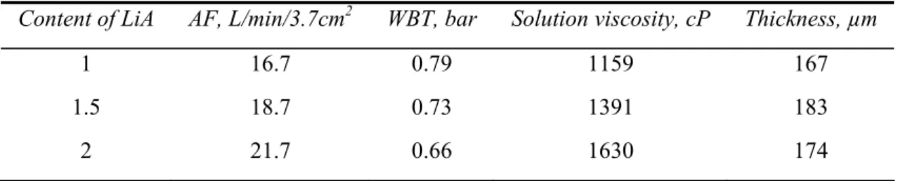
Table 6. The influence of the lithium salt content in casting solution on Fortex 1.2 membrane properties... 24
Table 7. The influence of dissolving temperature on the performance of Fortex 1.2 membrane (2% of LiA) ... 25
Table 8. Effect of coagulation bath composition on the performance of Fortex 0.1membrane prepared with use of polymer S1... 26
Table 9. Effect of coagulation bath composition on the performance of Fortex 0.1 membrane prepared with use of polymer S2... 26
Table 10. The influence of dissolving temperature on the performance of membranes prepared in standard alcohol/DMAc coagulation bath ... 28
Table 11. The influence of dissolving temperature on the performance of membranes prepared in coagulation bath DMAc:Water (15:85)... 28
Table 12. The influence of dissolving temperature on the performance of membranes prepared in coagulation bath DMAc:Water (30:70)... 28
Table 13. The influence of dissolving temperature on the performance of membranes prepared in coagulation bath DMAc:Water (50:50)... 28
Table 14. Influence of coagulation bath DMAc:Water (50:50) temperature on membrane properties 29 Table 15. Influence of dissolving temperature on membranes prepared without pore former and using DMAc:Water (50:50) coagulation bath... 30
Table 16. Fortex 0.2 membranes prepared with use coagulation baths of different composition ... 31
Table 17. Influence of type of pore former on membrane properties... 31
Table 18. Effect of dissolving temperature on Fortex 0.2 membrane prepared from polymer S1 and LiA as pore former ... 32
Table 19. First industrial trial of Fortex 3.0 membrane with use of polymer S1 ... 33
Table 20. Second industrial trial of Fortex 3.0 membrane with use of polymer S1 ... 33
Table 21. Influence of water content in casting solution on membrane properties... 33
Table 22. Industrial trial of Fortex 3.0 membrane with use of polymer S2 ... 34
Abbreviations
PS – Polysulfone PES – polyethersulfone PI – polyimide
PTFE – polytetrafluorethylene PVDF – poly(vinylidene fluoride) SEM – scanning electron microscopy
FT-IR – Fourier transform infrared spectroscopy XRD – X-ray diffraction
DMAc – N,N-dimethylacetamide HMPA – hexamethylphosphoramide TMU – tetramethylurea
DMSO – dimethylsulfoxide DMF – N,N-dimethylformamide NMP – N-methyl-2-pyrrolidone TEP – triethylphosphate
TMP – trimethylphosphate PVP – poly(vinyl pirrolidone) PEG – poly(ethylene glycol) AF – air flow
1
.
Introduction
1.1. Background and motivation
Over last decades, many researches have been performed in the field of novel membrane material development with the aim to achieve improved characteristics, such as high selectivity and high permeability. Nowadays, the membrane processes could be found in great variety of industrial process. Some of these applications require not just wonderful transport properties, but also high chemical, physical and thermal stability [1, 2]. Recently, poly(vinylidene fluoride) (PVDF) became one of the mostly used hydrophobic materials. Firstly, comparing with other materials such as polysulfone (PS), polyethersulfone (PES) and polyimide (PI), PVDF is relatively more hydrophobic [3]. Secondly, some other hydrophobic materials, such polypropylene, polyethylene, polytetrafluorethylene cannot be dissolved in commonly used solvents at low (room) temperatures. Thus, the membranes from these materials are produced by stretching and thermal methods, and the resulting membranes possess the symmetric structure with large pore sizes. In fact, PVDF is the only hydrophobic polymeric material, which could be dissolved in organic solvents with further asymmetric membrane preparation via phase-inversion process [4]. Moreover, this material attracted significant attention due to outstanding properties such as high mechanical strength, thermal and chemical resistance. Currently, PVDF membranes are extensively applied in various ultrafiltration and microfiltration processes, mainly for water and wastewater treatment. Additionally, this type of membrane material is a potential candidate to be used in membrane contactor applications [5, 6]. Finally, PVDF can be considered as pure polymer by possessing a low level of extractables, which allows its implementation in biomedical and bio-separation applications [3].
The membrane preparation basing on semi-crystalline polymer, such as PVDF is more difficult in comparison with glassy polymers. The main reason for such a complexity is in the fact that membrane could be formed by two different mechanisms: liquid-liquid demixing and/or crystallization (solid-liquid demixing) during phase-inversion processes [7]. By each mechanism specific membrane of different morphology could be obtained. The liquid-liquid demixing leads to the formation of asymmetric structure with dense layer on the top, while the crystallization process results in microporous structure with interconnected crystalline particles. Practically none of these mechanisms is an exclusive in the membrane formation, and its final structure is a result of combination of these mechanisms [4]. The domination of one mechanism over another is governed by different membrane preparation parameters, such as composition of dope solution, presence of additives, type of solvent and nonsolvent used, temperature of coagulation bath and dissolving temperature during the solution preparation. Thus, by varying each of these parameters can lead to the formation of membrane with completely different morphological and transport properties.
membrane production, it is almost impossible to have 100% of non-solvent in the coagulation bath throughout the whole manufacturing process, because of continuous wash-out of solvent from the membrane. Thus, it is essential for the industrial process to find suitable coagulation bath initially composed of mixture solvent/nonsolvent, which composition could be controlled by simultaneous addition of non-solvent during the membrane production.
1.2. Objectives
The objectives of this work are to develop the methodology of PVDF membranes production with predefined characteristics at laboratory level and transfer the procedure to the industrial scale production.
In order to achieve final target the following tasks were performed:
1) The influence of the preparation conditions on the resulting membrane properties. The effect of mixing temperature during the dope solution preparation, presence and type of additives and composition of coagulation bath on the resulting membrane properties were evaluated;
2) Laboratory research results transfer to the industrial scale. The reproducibility of the membrane properties developed in the laboratory during industrial production was evaluated.
2. Literature review
2.1. Microfiltration membranes
2.1.1. Historical development of membranes and membrane classification
The first information about membranes comes from 1748, when Abbe´ Nolet firstly used the term “osmosis” describing the transport of water through a semi-permeable diaphragm. Since that time the development of membranes had a lot of important milestones. One of them was the development of asymmetric membrane with thin dense top layer and porous support by Loeb and Sourirajan. This novel membrane gave ability to obtain one order of magnitude higher water flux at reverse osmosis process, meaning that this process became more practically and commercially attractive. Thus, a half of the century ago some fundamental research of the membrane science had already been conducted and some principals of membrane formation were investigated, but still membranes were used mainly in laboratory scale, due to problems with selectivity, cost and speed of the process. However, over the last half of the century the membrane science underwent great improvement in different aspects and the aforementioned problems were solved to the extent that membranes became extensively used in different separation processes [11].
In principle, all membranes can be classified according to the size of the pores on ones for: reverse osmosis, ultrafiltration and microfiltration. The range of pore sizes determining the application of membrane is depicted on Fig. 1, as well as the comparison with conventional filtration.
Fig. 1. Membrane classification basing on the pore size and their comparison with conventional filtration [11].
As it could be initially concluded from the Fig. 1 the reverse osmosis membranes possess pores of the size smaller than 2 nm (20 Ǻ), however in real membranes no pores could be observed (membrane is dense) and the transport occurs through the free volume areas, while ultrafiltration and microfiltration membranes possess pores of the ranges 2 – 100 nm and 100 nm – 10 μm, respectively. In other words, in case when the particles with sizes over 100 nm should be removed from the solution, the more open – microfiltration membranes may be used. In case, when the macromolecules of molecular weight from 104 to more that 106 should be filtered out of the solution, the membrane should be denser, thus the ultrafiltration membranes are more suitable for this application [12].
2.1.2. Mass transport models through microporous membrane
characteristics. This type of filtration model is more frequently observed. However, sometimes the microfiltration membrane has the smaller pores in the top layer than the size of the particles that have to be removed. In such a case the screen filtration is observed. This type of separation occurs on the surface of the membrane where filtered particles are accumulated [11].
Fig. 2. Depth filtration mechanism (a) and screen filtration mechanism (b) [11].
Aforementioned accumulation of particles on the membrane surface results in the phenomena called concentration polarization, the situation when flux through the membrane is decreased due to the formation of the “cake” (layer of particles stick to the membrane surface) that brings additional resistance to mass transfer. In other words, during the filtration process the solvent permeates through the membrane, while the solute is accumulated at the membrane surface leading to an increase in the solute concentration at the membrane surface and as a result the performance of membrane decreases significantly [12].
2.1.3. Materials used for microfiltration membranes preparation
The selectivity of microfiltration membranes are mainly determined by the pore size and by pore size distribution; however, choosing the appropriate material, such characteristics as adsorption, thermal and chemical stability should also be considered. These parameters are of high importance, because they determine the propensity of membrane towards the fouling (adsorption characteristics) and restrict the range of applications and possible cleaning methods applied for the membrane (chemical and thermal stability). In fact, the choice of material is first of all based on the fouling prevention and ease of cleaning process [12]. The typical materials used for the microfiltration membrane preparation are listed in the Table 1.
Table 1. Polymers for microfiltration membranes with respective chemical structure [4-12].
NAME OF POLYMER MATERIAL CHEMICAL STRUCTURE
Polycarbonate
Poly(vinylidene fluoride)
Polytetrafluorethylene
Polypropylene
Polyamide
Cellulose ester
Polysulfone
Poly(ether imide)
Polyetheretherketone
Each of material presented in the table above possesses one or more attractive properties. The first listed material – polycarbonate is usually selected due to its wonderful mechanical properties. Another important material for the microfiltration membrane preparation is cellulose and its derivatives (cellulose nitrate and cellulose acetate). These materials possess outstanding anti-fouling properties; however it is very sensitive to thermal and chemical influences [12]. Moreover, the polyamides should also be mentioned in the context of microfiltration membranes. According the chemical structure of monomers used for the polymer production the aromatic and aliphatic polyamides could be distinguished. For the purpose of microfiltration membrane production mainly the aliphatic polyamides are used. Although they possess good chemical stability, their thermal resistance is limited to the temperatures less than 100 °C which bring significant constrictions in terms of cleaning possibilities. Finally, the hydrophobic materials such as polytetrafluorethylene (PTFE), poly(vinylidene fluoride) (PVDF) and polypropylene are frequently used due to their relatively high crystallinity and high thermal and chemical resistance [12]. Since the poly(vinylidene fluoride) was used in current work, its chemical and thermal properties as well as its crystalline structure will be discussed in more details in the next chapters.
2.1.4. Porous supports used for membrane production
Porous support is a porous material used for composite membrane formation and improvement of their mechanical properties. Such a supports in the form of film of thickness 50-250 μm and different porosity are commonly produced from inert materials: polyethylene, polypropylene, aliphatic and aromatic polyamides etc. These materials are normally processed in films by means of physicochemical (i.e. hot pressing) or mechanical (sewing-knitting) methods. Moreover, sometimes other microfiltration and ultrafiltration membranes of different porosities are used as porous support.
In order to be used as support for asymmetric membrane the porous film should meet some requirements: 1) mechanically support thin selective layer of the membrane, 2) possess maximally open structure, which brings no additional resistance to mass transfer; 3) possess narrow pore size distribution, and, 4) be free from macrovoids, which can decrease the mechanical strength of membrane during use at high pressure applications [23].
some other methods could be utilized: interfacial polymerization, graft polymerization of monomers from gaseous phase, plasma polymerization, and precipitation of different compounds on the surface or inside the pores of the support.
Finally, polypropylene or polytetrafluorethylene porous supports could be used for production of supported liquid membranes by impregnation of needed organic solvent or solution. In this case, the porous support acts as a matrix carrying the liquid, which perform the functions of membrane [24].
2.2. Properties of poly(vinylidene) fluoride
2.2
.
1.
Thermal and chemical stability of poly(vinylidene) fluoride
Poly(vinylidene) fluoride (PVDF) is a semicrystalline polymer composed of repeating units -[CH2-CF2]- with the degree of crystallinity in the range of 35 – 70 %. Commercially available PVDF
is manufactured by emulsion or suspension radical polymerization of 1,1-difluoroethylene [25].
It is well-known that polymers containing fluorine side groups are more thermally and chemically stable than non-fluorinated ones. This property is related to the fact that fluorine is more electronegative atom than hydrogen, and consequently, the C–F bond is more stable that C–H. By this the overall polymer chain gains superior stability characteristics in comparison to non-fluorinated hydrocarbons. Thus, PVDF withstand exposure to harsh thermal, chemical and ultraviolet environment. It could be used at temperature range from -62°C to 149°C. Moreover, the continuous use under temperature of 149°C results in no oxidation and no thermal degradation [26].
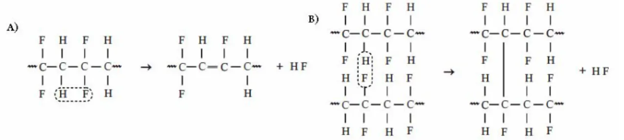
Some studies about thermal degradation of PVDF were performed to have better understanding of the limiting conditions for use of this material. The thermal induced polymer degradation was shown in several papers and all of them state that the mechanism for its degradation is the dehydrofluorination. This process could be intramolecular and intermolecular. Both variants are shown on the Fig. 3. The intramolecular dehydrofluorination leads to the formation of double (–C=C–) bond, while the intermolecular mechanism results in the polymer cross-linking [27].
Fig. 3. The intramolecular (A) and intermolecular (B) mechanisms of dehydrofluorination.
Poly(vinylidene) fluoride is well-known for its high chemical resistance. However, some chemicals still can cause degradation of the polymer. According to the information presented on Arkema (one of main PVDF suppliers) web-site, different organic (strong acids, aldehydes, ketones and esters) and inorganic (salts and amalgams) compounds are not recommended to be used in contact with PVDF. Some of these chemicals can cause problems if they are used in pure state (acetophenone, chlorosulfonic acid), while some of them can have negative effect even in the form of aqueous solution (bytilamine, chloroacetic acid) [28].
bonds. This conclusion was justified by utilization of analytical tools, such as FT-IR and UV-visible spectroscopy [30]. Additionally, Benzinger et al [31] performed the study about the effect of different acids, bases and oxidants on PVDF membranes. It was demonstrated that PVDF was stable during long-term (several months) test to all the analyzed compounds apart from concentrated solutions of sodium hydroxide. Finally, Li et al [32] showed the influence of temperature on PVDF stability being in contact with sodium hydroxide solution. It was observed that elevated temperatures are favoring and facilitating the PVDF degradation due to attack of NaOH.
2.2.2. Crystallinity and polymorphism of poly(vinylidene) fluoride
The spatial distribution of fluorine and hydrogen atoms inside the polymer backbone determines the crystalline structure of PVDF. There are at least four different types of crystals which PVDF can form:
α, β, γ and δ structures or phases [33].
The Fig.4 represents the atomic structure of α and β forms. The non-polar α form has monoclinic lattice with the trans-gauche (TGTG’) conformation of polymer chain. The sigh G’ shows the bond that turns the carbon polymer backbone for 60° angle from the plane. This deviation is governed by the repulsion forces present between the side groups of the polymer. In fact, such a conformation has lower energy, which could be an explanation for the fact that mainly αstructure is forming from the polymer melt. This form is believed to be the most stable; however, other structures are also stable.
Fig. 4. The atomic structure of α (left) and β (right) forms of PVDF.
The polar β structure has planar zigzag form, where all trans bonds are remaining on the same plane. Two different organizations inside βstructure are possible (Fig. 5): head-to-head and head-to-tail. The head-to-tail organization creates the very organized crystalline structure with improved packing density and reduced intermolecular strain. This type of organization possesses interesting piezo- and ferromagnetic properties. Basing on van der Waals forces, which are present between the atoms in PVDF chains, the β phase is more stable in intermolecular level, while αform is more likely to be formed at intramolecular level. The γ phase has orthorhombic lattice close to β one, but having slightly different sequence of trans and gauche bonds. This structural organization could be obtained by implementation of crystallization at high temperature. Finally, the δ phase is analogous to α phase with one main difference: δ phase is polar [34, 35]. In general, during the membrane formation αand β phases are mainly formed and understanding of how membrane preparation conditions can influence the formation of each phase is of high importance.
Since the PVDF backbone has only small side groups, this polymer is flexible, which gives ability to convert different phase from one to another. Some possible ways to alter the conformation of PVDF crystalline structure are shown on Fig. 6.
Fig. 6. Possible techniques used for phase transformation.
As it could be seen from this scheme that in order to convert one structure into another, different techniques could applied, such as drawing and annealing at different temperatures, applying electric field (poling) or annealing at high pressure [36].
Various analytical tools are used for the determination of different crystalline forms presence in the membrane. The main methods are Fourier transform infrared spectroscopy (FT-IR) and X-ray diffraction (XRD). It was shown by Gregorio [37] that each phase has characteristic bands on IR spectra: α phase could be determined at 531, 612, 766, 795, 855, and 976 cm-1, while the β phase – at 470, 511 and 840 cm-1, finally, the presence of γ phase can be justified by the presence of bands at 430 cm-1. The interpretation of XRD possesses rather large uncertainty, because lattice parameters of α and β structures are not uniform. Additionally, if both phases are present their diffractive peaks are overlapping in the area 2θ=20°. However, the presence of α phase can be justified by the presence of peak in the region 2θ=25-30° [38].
Numerous researches were performed to evaluate the influence of the membrane fabrication conditions on the formation of α and β phases, and ultimately on membrane characteristics. Tao et al
[35] has demonstrated that the type and power of solvent has strong influence on the membrane crystalline phase. In their work, four organic solvents with different affinity to PVDF were used. It was demonstrated that the lower Hansen solubility parameter disparity of pair PVDF-solvent, the lower the β phase content in final membrane. Consequently, the better dissolved PVDF favors the formation of α phase during phase inversion process.
Wang et al [39] performed the research related to the coagulation bath temperature on the PVDF membrane crystallinity and presence of particular crystalline forms. According to this investigation, the highest degree of crystallinity is observed at lowest analyzed temperature. Concerning the α and β phases formation, it was demonstrated that at the highest temperature of coagulation bath favored the formation of solely α phase, while at the lowest temperature the mixture of both these phases was observed. Similarly, Cheng [8] performed the studies of coagulation bath temperature on the different crystalline phase formation. It was demonstrated that at higher temperature α is more likely to be formed, while in the membrane prepared at lower temperature spherical crystallites with β crystal structure are mainly observed.
dimethylformamide/1-octanol was used. The obtained results demonstrated that by increasing the dissolving temperature the larger spherical crystallites are obtained, while the total membrane crystallinity remains without significant changes. The same observations were reported by Wang et al
[39] in their study of dissolving temperature on membrane morphology. It was shown that at higher temperatures larger PVDF particles were formed.
2.3. Phase inversion technique: immersion precipitation method
The history of PVDF membranes production started from around 1980s [3]. Currently, the most widespread technique in laboratory practice as well as in commercial membrane fabrication is phase inversion, in particular the immersion precipitation method, due to its simplicity and production process flexibility. These advantages give possibility to keep the cost of production on the low level, which is also attractive from commercial point of view [23].
Basically, the phase inversion process could be described by transformation of thermodynamically stable polymer solution from a liquid to a solid state under some influence. This transition may be induced by elevated temperatures (thermally induced phase separation), by influence of vapour (vapour-induced phase separation), by controlled evaporation of solvent or by immersion in the coagulation bath containing non-solvent (immersion precipitation). The later technique is the main one for the industrial production of the asymmetric membranes [3]. The schematic representation of phase inversion process is depicted on Fig. 7. The polymer solution, usually called as the casting or dope solution, is cast on the top of the appropriate support with use of a casting knife. The thickness of the polymer layer and, consequently, the thickness of the membrane are dependent on the adjustment of this casting knife. Then the film is immersed in a coagulation bath filled with nonsolvent where the polymer precipitation (phase inversion) occurs and the membrane is formed. The obtained membrane can further be subjected to washing, drying or/and post preparation treatment.
Various parameters can influence the morphology and the performance of produced membrane [12]. The influence of these parameters is not standard in all the cases and should be precisely studied for each system. Thus, the analysis of each parameter and its effect on the fabricated membrane is of high importance from both academic and industrial point of view.
Fig. 7. Schematic representation of phase-inversion process [12].
2.3.1. Mechanisms of membrane formation during phase inversion: thermodynamic and
kinetic aspects
The characteristics of membrane prepared with use of phase inversion technique are dependent on: 1) thermodynamic aspects of membrane formation, and 2) kinetics of the system, the rate of phase inversion during immersion precipitation [41]. In order to have understanding of the thermodynamic aspect of membrane formation, the ternary phase diagram can be used as a useful source of information [12]. The kinetic aspect should be understood as the rate of solvent-nonsolvent exchange, which is an important factor influencing the structure of pores in the fabricated membrane [42].
2.3.1.1. Thermodynamic aspect of membrane formation
From the thermodynamic point of view, the system polymer-solvent-nonsolvent could be depicted in a ternary phase diagram (Fig. 8). This diagram gives information about system composition, its behavior in response on addition of any of its components and enables prediction of phase state of the system depending on its composition.
Fig. 8. Ternary diagram of polymer-solvent-nonsolvent system [43].
The corners of the triangle represent pure components (polymer, solvent and nonsolvent), the axes of the triangle depicts the binary combinations of connected compounds, and any point inside the triangle shows the composition of the system containing all three components [44]. The key elements of this diagram are: binodal curve, spinodal curve, a critical point, tie lines, and a glassy (gelation) region. [43]. The binodal curve separates the homogeneous and metastable regions. The former region represents the range of system compositions, where it is thermodynamically stable, all three components are miscible and no apparent changes occurs with the course of time, while in latter region the system undergoes the phase separation by nucleation and growth. This behaviour is observed until system reaches spinodal curve, which represents the boundary of unstable region, where the system is separated on two equilibrium phases (polymer-rich and polymer-lean) due to thermodynamic instability. The points on the binodal curve showing the compositions of these phases are connected by tie lines. Finally, the point where binodal and spinodal meet is called the critical point [43, 45].
thermodynamically stable conditions slowly and enters the metastable region of the phase diagram between the binodal and the spinodal curves. In such a situation new nuclei are formed and become stable if the activation energy for nuclei formation is higher than their surface free energy [47].
Two different types of nucleation and growth can be distinguished in case of solid-liquid demixing phase separation process. If the system enters the metastable region of the phase diagram below the critical point, nucleation and growth of the polymer-rich phase occur in polymer-lean phase. In this case, the powdery agglomerates with low integrity will be obtained and, thus, membrane is not formed. In contrary, if the system enters the metastable region above the critical point the opposite phenomena is observed – polymer-lean phase is nucleating and growing in polymer-rich phase. As a result the matrix of membrane is formed from the polymer-rich phase, while the porous structure is created from the polymer-lean phase [43].
Moreover, going back to liquid-liquid demixing mechanism, in order to predict the morphology of the fabricated membrane, it is important to know the behaviour of polymer solution upon its contact with nonsolvent. In particular, the changes in its composition with time are of high importance. Depending on the time needed by system to move from stable to unstable region one can distinguish two different ways: instantaneous demixing and delayed demixing. The former one means that the membrane structure is formed immediately after its contact with the nonsolvent, while the latter way takes some time before the membrane get the final structure [12]. The composition path of the system in cases of instantaneous demixing and delayed demixing are depicted on Fig. 9.
Fig. 9. Composition path of the casting solution in instantaneous (left) and delayed demixing (right) [12].
Since the process of the exchange between cast film and coagulation bath starts at the interface polymer solution/nonsolvent, the first changes in composition are observed in the top of the membrane. On the Fig. 9 the point “t” represents the composition of the membrane on the upper layer, while point “b” respects to the bottom of the membrane. Additionally, according to the Fig. 9, in case of the instantaneous demixing, layer of the film located just beneath the top layer have crossed the binodal curve meaning that the liquid-liquid demixing started less than 1 second after the immersion in the bath with nonsolvent. In contrast, in the case of delayed demixing, all layers beneath the top layer are still in the one-phase region. Thus, it could be stated that no demixing occurs immediately after immersion. With the course of time, the compositions beneath the top layer will cross the binodal curve and, consequently, process of the liquid-liquid demixing will occur [12].
2.3.1.2. Kinetic aspect of membrane formation
Up to now, two different approaches to investigate the dynamics of phase separation are developed. The first approach, usually referred as cast-leaching, means the monitoring of the coagulation bath composition. Several works showed that the outflow of a solvent from a cast film has the diffusion character [50]. In other words, the mass transfer of solvent in coagulation bath from the polymer solution is rate limiting step in coagulation process. In the second approach, the optical microscopy is applied to follow the process of polymer film coagulation [51]. The studies in the frame of this approach demonstrated that the propagation rate of the film precipitation front was proportional to the square root of time (t1/2) up to 60% of the thickness and that the mass transfer had the diffusion character. Additionally, several different models describing the solvent-nonsolvent exchange were developed [49]. Finally, in 1996 the model describing the polymer concentration at the interface coagulation bath/cast film was proposed [52]. The application of this model brought to the conclusion that different solvent-nonsolvent systems results in different membrane structures.
2.4. Influence of preparation conditions on membrane morphology and performance
As it was discussed previously, various parameters of phase-inversion process can influence the structure and performance of fabricated membrane. Numerous research groups presented results of their studies of preparation conditions effect on the membrane morphology and separation characteristics. All these research results could be grouped with respect to the specific analyzed parameter.
2.4.1. Effect of solvent
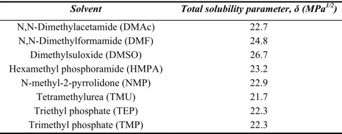
The choice of solvent is a crucial parameter that determining the membrane appearance and performance. The suitable solvent enables uniform distribution of polymer molecules in the solution, while the bad solvent use will lead to the aggregation of polymers chains. It was identified that eight solvents out sixty four analyzed can be considered as good solvents for PVDF [53]. They are N,N-dimethylacetamide (DMAc), hexamethylphosphoramide (HMPA), tetramethylurea (TMU), dimethylsulfoxide (DMSO), N,N-dimethylformamide (DMF), N-methyl-2-pyrrolidone (NMP), triethylphosphate (TEP) and trimethylphosphate (TMP). The propensity of each of these solvents to dissolve PVDF can be characterized by means of Hansen solubility parameters (Table 2 [54]). The higher value of δt means the higher solubility power of particular solvent.
Table 2. Hansen solubility parameters of common solvents for PVDF
Solvent Total solubility parameter, δ (MPa1/2)
N,N-Dimethylacetamide (DMAc) 22.7 N,N-Dimethylformamide (DMF) 24.8 Dimethylsuloxide (DMSO) 26.7 Hexamethyl phosphoramide (HMPA) 23.2 N-methyl-2-pyrrolidone (NMP) 22.9 Tetramethylurea (TMU) 21.7 Triethyl phosphate (TEP) 22.3 Trimethyl phosphate (TMP) 22.3
The effect of four different solvents on the PVDF crystalline structure was analyzed by Tao and coworkers [35]. The used solvents were: triethylphosphate (TEP), hexamethylphosphoramide (HMPA), trimethylphosphate (TMP) and N,N-dimethylformamide (DMF). The results of this work demonstrated that the polymorphism of PVDF membrane is dependent on the solubility power of the solvent. The better solvents, which were leading to more complete dissolution of polymer, were favoring the α phase formation, while the poorly dissolved PVDF solution tended to form the β phase.
2.4.2. Effect of additives in the casting solution
The addition of additives to the dope solution is one way to improve or change the performance of ultimate membrane. The additive can perform such functions as: pore formation, increase of solution viscosity and/or facilitate the process of phase inversion [3]. Additives used in PVDF membrane preparation could be divided into four categories: 1) polymeric additives, such as poly(vinyl pirrolidone) (PVP) and poly(ethylene glycol) (PEG); 2) weak nonsolvents such as glycerol; 3) weak cosolvents such as ethanol and acetone; and 4) low molecular weight additives, such as LiCl and LiClO4 [55].
The addition of PVP or PEG leads to the increase of solution viscosity. As a result the miscibility between the cast solution and nonsolvent is reduced. Thus, the kinetics of phase separation became hampered, while the thermodynamic aspect of membrane formation receives the dominating role [55]. In terms of membrane structure, it was demonstrated that addition of PVP leads to the decrease of mean pore size and the increase of the effective porosity [56]. Since PVP is of hydrophilic nature its presence in the casting solution enhance the influx of nonsolvent during the coagulation process, which leads to the formation of finger-like macrovoids [3, 55]. Additionally, PVP is a high molecular weight compound, meaning that it can’t be completely washed out from the membrane. The leftovers of this additive in the ultimate membrane can change its hydrophobicity and, consequently, make it inappropriate for the membrane distillation process [4].
The effect of glycerol addition to the casting solution was studied by Shih and coworkers [57]. In their work they used two different solvents for PVDF dissolution and water as nonsolvent. The results of this research demonstrated that membranes obtained using TEP as a solvent possessed increased mean pore size and effective porosity with increase of glycerol content in the casting solution. In contrary, while using DMSO as a solvent by increasing the glycerol content in dope solution the ultimate membranes with increased mean pore size and decreased effective porosity were obtained. These observations were related to different mutual affinity between used solvents and nonsolvent.
The effect of LiCl on casting solution, membrane morphology and performance was shown in numerous research papers. Its addition to the dope solution leads to the significant increase of viscosity. This effect is usually related to the formation of complexes between Li+ and polar solvent (i.e. DMAc) or/and the electron-donor group of PVDF [58]. The increase of LiCl content in casting solution leads to the formation of macrovoids, and, consequently, to higher porosity and increased maximum pore size [59]. This effect is related to the fact that LiCl has a good affinity to water, meaning that during the coagulation process the inflow of water is enhanced and, therefore, the interconnected structure is obtained [60]. However, this behavior is observed only up to certain content of LiCl in dope solution. It was shown that at higher concentration the formation of macrovoids is suppressed [61]. This phenomenon is attributed to the competition between thermodynamic and kinetic effects during the phase inversion process. Thus, it was concluded that at lower LiCl concentration the dominant mechanism was instantaneous liquid-liquid demixing, while at higher additive content the membrane formation was mainly governed by delayed demixing process.
Another salt of litium (LiClO4) is also widely used in PVDF membrane formation. The addition of
LiClO4 had the same effect on solution viscosity as of LiCl, due to same aforementioned reasons. At
low content of LiClO4 in dope solution the increase of mean pore size of and more sharp pore size
increase of LiClO4 content in the casting solution leads to the larger macrovoids formation in the
ultimate membrane [62].
2.4.3. Effect of dissolving temperature
The effect of PVDF dissolving temperature during the casting solution preparation on the membrane morphology was studied in some works. Wang et al 2009 [63] performed the research, which demonstrated the changes on the morphology of PVDF membranes prepared from four different temperatures (50°C, 70°C, 90°C and 120°C) with water as a nonsolvent. It was shown that all the membranes were of an interconnected structure. The cavities between the particles were of different size: starting from around 0.3-0.6 μm at the lowest dissolution temperature and increasing three to four times with every step of temperature increase. Additionally, Mi-mi Tao et al [35] applied three different dissolution temperatures (50°C, 80°C and 110°C) for the casting solution preparation with further analysis of their influence on membrane morphology and crystalline structure. It was concluded that the total number and the volume of macrovoids inside the membrane is increasing with the increase of dissolution temperature. Moreover, it was found that lower temperature favors the formation of β phase, while the higher temperature leads to the better dissolution of PVDF and, therefore, enhanced mobility of polymer chains which results in their arrangement in α form. Finally, Ahmad et al [9] studied the effect of PVDF dissolution temperature on the pore size distribution. The author applied various temperatures in the range from 20°C to 100°C with the step of 20°C. It was found that the narrow pore size distribution is obtained only at temperatures not exceeding 40°C, while at temperatures greater than 60°C the pore size distribution became much wider with the shift of average size towards larger pores.
2.4.4. Effect of coagulation bath composition
As it was stated previously, since PVDF is a semi-crystalline polymer, the membrane formation process occurs via two different mechanisms. In the immersion-precipitation method of phase inversion the composition of coagulation bath has a crucial effect on the ultimate membrane morphology and performance. In general, all the nonsolvent applied for the PVDF precipitation could be divided into two groups: strong and weak (soft) ones [23]. The typical example of strong nonsolvent is water and its presence in coagulation bath favor the membrane formation via instantaneous liquid-liquid demixing which results in asymmetric membrane structure with dense layer on the top and finger-like structure beneath [10]. On the other hand, the addition of solvent in coagulation bath can lead to the delayed demixing. Choi et al [6] demonstrated that by increasing the DMAc content in the coagulation bath the membrane morphology was gradually changing from finger-like to the sponge-like structure. This observation was attributed to the changes from the instantaneous to the delayed demixing process. In other words, the precipitation power of coagulation bath was approaching the one of weak nonsolvent.
In general, the typical compounds, referred as weak nonsolvent, are alcohols of different structure (C1-C8) [28]. It was demonstrated that using 1-octanol the membrane with symmetric structure composed of identical spherical particles was obtained indicating that the crystallization preceded liquid-liquid demixing [58]. Additionally, Deshmukh and Li [56] performed the study where for the PVDF membrane formation the mixture of strong and soft nonsolvents at different ratios was used. In particular, the effect of ethanol concentration in the mixed ethanol/water coagulation bath on membrane performance and morphology was evaluated. It was shown that by increasing the ethanol concentration from 0% to 50% the finger-like structure was changed to the sponge-like structure.
solubility parameter is, the slower is the process of liquid-liquid demixing, and, thus, the crystallization has enough time to occur and as a result the symmetric structure is formed.
2.4.5. Effect of coagulation bath temperature
The temperature of coagulation bath is one of the key parameters defining the ultimate membrane properties. Cheng [30] analyzed the coagulation bath temperatures in the range from 25°C to 85°C. It was demonstrated that the lower temperature was leading to the formation of sponge-like structure, while at elevated temperatures the finger-like structure was created. This result was explained by means of kinetics. At higher temperatures the exchange of solvent and nonsolvent is facilitated, and, therefore, the liquid-liquid demixing occurred at the early stage of membrane formation process. In contrary, at lower temperatures the mutual diffusion of solvent and nonsolvent is hindered, thus the dominating mechanism of membrane formation is crystallization. The same observation was done by Wang et al [65]. The authors analyzed three different temperatures of coagulation bath (15°C, 25°C and 60°C). The results of their research also revealed that due to differences in kinetics of solvent and nonsolvent exchange the different membrane morphology was obtained. Finally, the temperature of coagulation bath is also influencing the crystallinity of PVDF membrane. This effect in more details was described previously in chapter 2.2.2.
2.5. Microfiltration membrane characterization
The microfiltration membranes can be characterized with use of different techniques and their choice is normally made basing on the required membrane characteristics. Required characterization parameters for membranes could be divided into two groups: 1) structure-related parameters: morphology, pore size and pore size distribution, effective surface porosity, total porosity, crystalline structure (in case of semi-crystalline polymers) etc; and 2) permeation-related parameters: membrane permeability, molecular weight cut-off etc.
2.5.1. Mean pore size and effective surface porosity
Mean pore size and effective surface porosity are two important parameters influencing the permeation rates through the membrane. The gas permeation method is one of techniques applied to evaluate these two membrane parameters. There are two possible mechanisms of gas transport through the membrane: Knudsen diffusion and Poiseuille (viscous) flow [66]. The ratio of the pore radius (r) to the mean free path of gas molecule (λ) is the parameter which determines the mechanism of gas permeation [67]. In case r/λ>1, the dominating mechanism is the Poiseuille flow, while in case r/λ<1, the mechanism determining the gas permeation is Knudsen diffusion. The total gas flux in case of both mechanisms can be described as:
RT
l
P
P
r
Q
visμ
16
)
(
2 2 2 1 2−
=
(1)1 21/2
)
2
(
3
)
(
8
MRT
l
P
P
r
Q
KDπ
−
=
(2)where l is the length of the pore, µ is the gas viscosity, M – molecular weight of the gas, R is the universal gas constant, P1 and P2 are the gas pressure on the feed side and the permeate side, respectively.
2.5.2. Pore size distribution
Fig. 10. Schematic representation of pore size distribution [12]
As it could be seen from the figure above, two different specific pore sizes could be determined: nominal and absolute. The data about absolute pore size gives ability to tell that particles of the same or larger size are completely retained by membrane, while the nominal size indicates that particles of this size or larger are retained up to 95% to 98% [12].
There are number of methods allowing the determination of pore size distribution. The main of them are: gas-liquid displacement, mercury porosimetry, thermo-porometry, permporometry etc [68]. Each of these methods are based on the measurements of pressure needed to force a non-wetting liquid to flow through the pores of a membrane. The obtained data about applied pressure and corresponding membrane filling with the non-wetting liquid can be converted to the knowledge of pore sizes by applying the next equation:
r
P
=
2
γ
cos
θ
Δ
(3)where γ is the surface tension of the liquid, θ is the contact angle of the liquid on the inner surface of the pore, r is the radius of the cylindrical pore.
In more details the aforementioned techniques normally used for the determination of pore size distribution are described elsewhere [68].
In case of hydrophobic membranes the same principle is applied in the critical water entry pressure measurements. The water is brought to the direct contact with membrane surface and pressure is applied. The pressure at which the first bubble of water permeates though the membrane is called critical water entry pressure (CEPw). Knowledge about CEPw enables the determination of the largest
pore present in analyzed sample by implementing equation similar to previous one:
max
cos
2
r
P
=
−
γ
θ
Δ
(4)where r max represents the maximal pore size of the sample.
2.6. Hydrophobic microfiltration membranes for medical applications
Sometimes such filters are initially connected to intravenous tubing, while others must be attached just before use. In general, the size of filter membranes is varying from 5 to 0.22 μm. Theoretically, filters with pore size range of 1 to 5 μm are able to retain large particles and debris, but not fungi or bacteria. Filters that possess pores around 0.45 μm enable the removal of fungi and most bacteria. Finally, the filters, pore of which are not exceeding 0.22 μm, remove all fungi and bacteria [70]. In addition, the latter type of microporous membranes is considered sterilizing grade. Moreover, some suppliers also produce 0.1 µm membranes to insure the complete mycoplasma removal. Since under the certain pressure membrane wetting may occur, and consequently, bacteria will be able to pass through, majority of medical device manufacturers utilize the vent membranes with pore sizes in the range 0.1 or 0.2 µm [71].
However, it should be noted that the mechanism of bacterial retention by hydrophobic membranes from a gas stream is different in comparison to hydrophilic membranes in liquid filtering. Microorganisms usually are not present in free state in the air; they are usually attached to particles of aerosol or of the dust. Thus, during the air filtering majority of pathogens can be retained by membrane with pore sizes larger than microorganisms. In some cases, even membranes with pore sizes of 5 µm perform the 99.99% bacterial retention. Consequently, membranes with larger pore sizes may be used in specific cases having an advantage of higher air flow per unit of time [71].
In such application as intravenous injections, an injection solution has to be delivered with even pace. However, when the solution is delivered from a rigid vessel, air should flow into this vessel in order to prevent the vacuum formation inside the system. In this type of containers, the special sterile inlet for the air should be present and vent membranes offer such a possibility. In case of their usage, the air is sucked inside the vessel only when the liquid is delivered to the patient; when system is closed and the level of liquid is stable, no air is permeating through the vent membrane. Additionally, the hydrophilic filters used in intravenous systems apart from bacteria and particles remove air from the injection solution, and these formed air bubbles has to be removed from the system. In such cases, the use of vent membranes is also a good solution to the emerging problems [69].
Finally, apart from considerations of bacterial retention mechanism, the venting membranes selection should be also based on its intended use. Different solutions in terms of composition and nature can be in contact with the membrane (water, buffer solution, solution containing the proteins or drugs, blood, urine etc). Every solution has specific propensity towards wetting the membrane and, therefore, causing its failure. Thus, in some cases, a vent membrane is placed above the liquid surface in order to
3. Materials and methods
3.1. Materials
Poly(vinylidene fluoride) (PVDF) powder supplied by two different supplier (further named as S1 and S2) was used as polymer material. N,N-Dimethylacetamide (DMAc, Lot. 121058 and 118329) supplied by Brenntag was used as a polymer solvent without further purification. As a pore forming agents salt of lithium (LiA, Lot. 110865) purchased from Brenntag and another low-molecular-weight organic compound (Lot. 118075 and 114386), further denoted as organic pore former (OPF), were used. Since LiA is a highly hygroscopic compound, it was dried in thermostatic chamber during 24 hours at temperature of 80°C before use. Water used for the coagulation bath was obtained by reverse osmosis. The alcohol applied for coagulation was used as received. Depending on the membrane type two different non-woven supports named H (average thickness 120 μm) and S (thickness 150 μm) were used.
3.2. Methods
3.2.1. Membrane preparation in laboratory scale
3.2.1.1. Casting solution preparation
PVDF solutions were prepared at different temperature regimes by mixing the polymer powder in the solvent (DMAc) in a glass beaker, followed by constant mechanical stirring until complete polymer dissolution (normally 2 hours). The range of the dissolving temperatures was dependent on the membrane type. In general the bottom limit was set as 20°C and the upper limit to 40°C. The dope composition was varied by adding different additives to the dope solution or/and by changing the polymer concentration. In case of LiA use, it was dissolved in DMAc before polymer addition. However, in case of OPF usage it was added after polymer addition because of its high volatility. After complete polymer dissolution the casting dope was kept at room temperature for at least 18 hours to remove air bubbles. In case if room temperature was higher than dissolving one, the solution was kept on water bath at the temperature not exceeding the dissolving one. The viscosity of prepared and degassed polymer solution was evaluated by viscometer (Brookfield, DV-E viscometer) at 25°C. If the dissolving temperature was lower than 25°C the measurements of viscosity were conducted after membrane preparation in order to prevent the alterations of the solution properties.
3.2.1.2. Casting method and apparatus
3.2.2. Membrane preparation at industrial scale
The whole process of the casting solution preparation at industrial scale was conducted in 4 steps: components loading, mixing, filtration and degassing. The mixing procedure was performed during 6 hours instead of 2 hours in the laboratory. After preparation, the solution was transferred from the mixer to the storage tank. Between mixer and storage tank the filter was placed to remove large particles and non-dissolved agglomerates. Obtained solution was degassed at room temperature. Before membrane casting at industrial scale, the laboratory validation of prepared solution in terms of viscosity and membrane properties was done. During the industrial manufacturing the speed of support movement was set in agreement with standard membrane manufacturing protocol. The polymer solution was automatically cast onto a polyester non-woven fabric with the aid of the casting rolls with precise thickness control. The obtained film was immersed in the coagulation bath for at least 25 minutes. The nonsolvent mixture was continuously changed and circulated in order to keep the ratio solvent/nonsolvent and quantity of additives in coagulation bath in previously determined limits. For the determination of solvent and additives quantity in the coagulation bath the refractometer and conductometer “HI 8733” Hanna Instruments, USA, respectively, were used. Subsequently, the precipitated supported membrane was immersed in water washing bath to remove traces of solvent and additives for at least 30 minutes. The membrane was collected by rotating roll and subjected to continuous drying.
3.2.3. Membrane characterization
The membranes prepared in the laboratory were characterized in terms of air flow, critical water entry pressure and thickness. For the determination of air flow the circular sample with area of 3.7 cm2 were cut and placed in the cell. This housing was assembled as shown on Fig. 11.
.
Fig. 11. Housing for the air flow measurements
The measurements of gas permeability through the membrane were performed under pressure of 0,930 bars (700 mmHg) for membranes Fortex 0.1 and Fortex 0.2 and 0,347 bars (260 mmHg) for membranes Fortex 1.2 and Fortex 3.0. The critical water entry pressure (water breakthrough (WBT)) was measured using the cell TA234 equipped with pump of maximum pressure equal to 5 bars. As soon as the sample was placed inside the device the pressure was continuously increased. WBT was considered as pressure at which the first water droplet appeared on another side of the membrane.
The membrane thickness was determined with micrometer Mitutoyo, Japan..
The morphology of prepared membranes was examined using Scanning Electron Microscopy (SEM). The samples were mounted on SEM stubs, and sputtered for 60 seconds for examination under an SEM (JEOL 6360). The images were taken under proper accelerating voltage and working distance. Some of the samples were fractured in liquid nitrogen to reveal the cross-sections for SEM observation.
The crystalline structure of fabricated membrane was analyzed by Fourier transform infrared spectroscopy. FT-IR spectra of fabricated membranes were recorded over the range of 4000–400 cm-1 with Bruker model Alpha ATR Diamond.
4. Results and discussion
The membrane formation by the phase inversion process induced by the nonsolvent means the transition of initially homogeneous solution into two equilibrium phases, because of solvent/nonsolvent exchange. One phase, usually referred as polymer-rich, results in the polymer matrix, while the second phase (polymer-lean) forms the pores inside. During the process of phase separation the polymer molecules can arrange in different structures which determine the morphology and properties of ultimate membrane. In principal, two different mechanisms of the membrane formation can be distinguished in case of PVDF material: liquid-liquid demixing and solid-liquid demixing (crystallization). Each of these mechanisms has a specific resulting structure and could be influenced by various parameters of membrane preparation process. The target of present research is to find the optimal production parameters which will allow fabrication of membranes with desired properties in terms of water repellency (or water breakthrough) and air permeability. In principal, the water breakthrough parameter of the membrane indicates the pressure at which the largest pore started to be wetted by water and this pressure is reciprocally proportional to the pore radius. The air permeability gives information about membrane porosity. In case of symmetric membrane, formed by solid-liquid demixing mechanism, this parameter indicates the porosity of the whole membrane, while in case of asymmetric membrane, resulted from liquid-liquid demixing process, only porosity of denser top layer is considered. In other words, if value of air flow is changed due to some alterations of membrane preparation conditions, this changes should be attributed to variation of total porosity of symmetric membrane or surface porosity of asymmetric one.
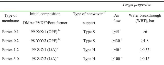
In order to achieve the target, the effect of different parameters on the ultimate membrane properties was studied. The techniques applied for the optimization of membrane production were: variation of polymer material (PVDF from different suppliers), changes of polymer dissolution temperature, modification of the casting solution composition by addition of additives of different nature and quantity, and alterations of coagulation bath composition. The starting point for each membrane type development as well as desired membrane properties were based on previous research conducted by R&D department of GVS Filter Technology Company and are presented in Table 3.
Table 3. The starting points and targeting parameters for all the membrane types
Target properties
Initial composition Type of nonwoven f Type of
membrane DMAc:PVDFa:Pore former support
Air flow
Water breakthrough (WBT), bar
Fortex 0.1 99-X:X:1 (OPF) b Type S ≥45 d >6
Fortex 0.2 98-Y:Y:2 (OPF) b Type S ≥430 d ≥1.8
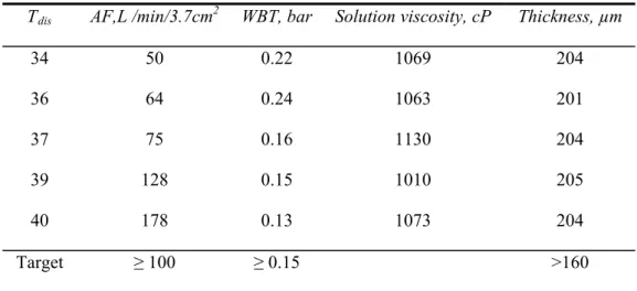
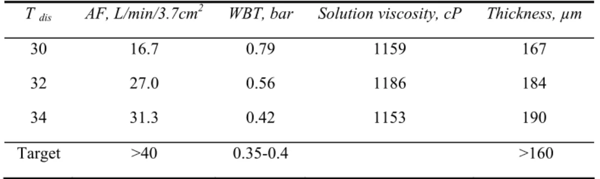
Fortex 1.2 99-Z:Z:1 (LiA) c Type H ≥40 e ≥0.35
Fortex 3.0 98-Z:Z:2 (LiA) c Type H ≥100 e ≥0.15
a
With respect to signed “Nondisclosure agreement” the exact composition of casting solution is hidden; however, relation between these values is X>Y>Z;
b
Organic pore former (OPF) was suggested for Fortex 0.1 and Fortex 0.2 membranes; c
The salt of lithium was suggested for Fortex 1.2 and Fortex 3.0 membranes; d
measured in L/h/3.7 cm2 under the pressure of 0.930 bar (700 mmHg); e
measured in L/min/3.7 cm2 under the pressure of 0.347 bar (260 mmHg);
f the choice of nonwoven support was dictated by the peculiarities of further membrane processing into final
![Fig. 1. Membrane classification basing on the pore size and their comparison with conventional filtration [11]](https://thumb-eu.123doks.com/thumbv2/123dok_br/16476599.732063/15.892.126.759.559.754/fig-membrane-classification-basing-pore-comparison-conventional-filtration.webp)
![Table 1. Polymers for microfiltration membranes with respective chemical structure [4-12]](https://thumb-eu.123doks.com/thumbv2/123dok_br/16476599.732063/16.892.101.799.808.1145/table-polymers-microfiltration-membranes-respective-chemical-structure.webp)
![Fig. 7. Schematic representation of phase-inversion process [12].](https://thumb-eu.123doks.com/thumbv2/123dok_br/16476599.732063/21.892.193.699.729.916/fig-schematic-representation-phase-inversion-process.webp)
![Fig. 9. Composition path of the casting solution in instantaneous (left) and delayed demixing (right) [12]](https://thumb-eu.123doks.com/thumbv2/123dok_br/16476599.732063/23.892.213.685.512.730/fig-composition-casting-solution-instantaneous-delayed-demixing-right.webp)