Susana Costa de Oliveira
Licenciatura em Engenharia de Micro e Nanotecnologias
Biomimetic Mineralization:
Encapsulation in Calcium Carbonate Shells
Dissertação para obtenção do Grau de Mestre em
Engenharia de Micro e Nanotecnologias
Orientador:
Professora Doutora Isabel Maria das Mercês Ferreira, Professora
Associada, Faculdade de Ciências e Tecnologia da Universidade Nova de Lisboa
Co-orientador: Professora Doutora Susana Isabel Pinheiro Cardoso de Freitas,
Professora Associada, Instituto Superior Técnico da Universidade Técnica de
Lisboa
Júri:
Presidente: Prof. Doutor Rodrigo Ferrão de Paiva Martins Arguente: Doutora Verónica Cristina Baião Martins Romão Vogal: Prof. Doutora Isabel Maria das Mercês Ferreira
iii
Biomimetic Mineralization: Encapsulation in Calcium Carbonate Shells
Copyright © Susana Costa de Oliveira, Faculdade de Ciências e Tecnologia, Universidade Nova de Lisboa, 2015
v
Acknowledgments/Agradecimentos
Antes de mais quero agradecer à minha orientadora, Professora Isabel Ferreira pelo apoio dado nesta etapa e por me ter deixado tentar concretizar o que imaginei. Desde montes de objetivos traçados, falhados e frustrações, cheguei até aqui e sei que evoluí com toda esta experiência. Resiliência é a palavra-chave desta tese.
Quero também agradecer ao meu co-orientador, Professor João Paulo Borges, que esteve sempre pronto para partilhar conhecimento, e como não podia deixar de ser, deixo uma linha especial para a Doutora Ana Baptista, que esteve sempre disponível mesmo quando não podia. A todo o restante grupo, Paulo Duarte, Inês Ropio, Filipe, Xana, Marisa, um obrigado, pois todos ajudaram de alguma forma, a que este projeto andasse sempre um pouco mais para a frente. Não podia ainda deixar de referir a Professora Carmo Lança, a Professora Helena, a Professora Suzete, o CJ e a Coro pela ajuda prestada e pelo acesso à câmara e ao microscópio, e tenho ainda de deixar um agradecimento à Ana Almeida pela análise dos ângulos de contacto, ambas ajudas essenciais para este trabalho.
Por fim mas não por último, quero agradecer imenso à instituição INESC-MN, à Professora Susana, que me recebeu e me deu acesso às instalações como se desde sempre tivesse feito parte da vossa casa. Obrigado por ter permitido que eu pudesse aprender com o seu grupo, ter ido para o INESC-MN desenvolver o dispositivo de microfluídica foi um passo importante que eu queria para este projeto, e uma aprendizagem fundamental ter passado da teoria à prática - deixo aqui também os parabéns pela organização das instalações. De todas as pessoas que aí conheci tenho de agradecer (e muito) ao Tomás e ao Tiago que me deram muito do seu tempo sem nada em troca, partilhando o seu conhecimento comigo e ajudando ativamente a resolver questões técnicas que foram surgindo. Obrigado ainda ao Zé e ao Eng. Fernando pela ajuda com o fabrico da máscara e pela boa disposição, à Virgínia pelas mais variadas ajudas e em particular com o perfilómetro e à Andreia pelo tempo disponibilizado na mill.
A vossa ajuda e paciência permitiu-me estar aqui hoje.
Aos amigos,
Do Lab, Dj Fi in tha House, Tomás-Talheres-de-Peixe, Susana sista do bronze, Cláudia Nails on Gels e à mascote Ana Sardine Hip Hop 2000, que tornaram os dias muito mais divertidos! “Porque quando uma pessoa acredita e trabalha, as coisas acontecem!”, T.M.; Do Ceni, Rachel, Inês, Tomás, obrigado pelas pipe connections e apoio moral, e ao AFM
master Mestre Tomás Calmeiro um muito obrigado pelo melhor filme 3D-AFM que já vi; À team fibras, B e Richie, que se há-de encontrar no gym para mais aventuras: #6pack_thereturn
E aos mais antigos: Melissa, Ana A., Carlos, Diogo I., Miguel e Diogo S.
vii
Abstract
Calcium carbonate biomineralization is a self-assembly process that has been studied to be applied in the biomedical field to encapsulate biomolecules. Advantages of engineering mineral capsules include improved drug loading efficiencies and protection against external environment. However, common production methods result in heterogeneous capsules and subject biomolecules to heat and vibration which cause irreversible damage.
To overcome these issues, a microfluidic device was designed, manufactured and tested in terms of selectivity for water and oil to produce a W/O/W emulsion. During the development of this work there was one critical challenge: the selective functionalization in closed microfluidic channels. Wet chemical oxidation of PDMS with 1M NaOH, confirmed by FTIR, followed by adsorption of polyelectrolytes - PDADMAC/PSS - confirmed by UV-Vis and AFM results, render the surface of PDMS hydrophilic. UV-Vis spectroscopy also confirmed that this modification did not affect PDMS optical properties, making possible to monitor fluids and droplets. More important, with this approach PDMS remains hydrophilic over time. However, due to equipment constrains selectivity in microchannels was not achieved.
Therefore, emulsion studies took place with conventional methods. Several systems were tried, with promising results achieved with CaCO3 in-situ precipitation, without the use of polymers or
magnesium. This mineral stabilizes oil droplets in water, but not in air due to incomplete capsule formation.
ix
Resumo
A biomineralização do carbonato de cálcio é um processo auto-regulado que tem sido estudado para aplicar na área biomédica para encapsulamento de biomoléculas. Entre as vantagens destas cápsulas encontram-se a melhor eficiência de encapsulamento e a proteção contra fatores externos. Contudo, os métodos tradicionais de produção resultam em cápsulas heterogéneas, e sujeitam as biomoléculas a calor e vibração, o que causa danos irreversíveis. Para ultrapassar estes problemas, um dispositivo de microfluídica foi desenhado, fabricado e testado em termos da seletividade para a água e o óleo para produzir um emulsão A/O/A. Durante o desenvolvimento deste trabalho houve um desafio crítico: a funcionalização seletiva em canais de microfluídica selados.
A oxidação por solução química do PDMS com 1M NaOH, confirmada por FTIR, seguida da adsorção de polielectrólitos - PDADMAC/PSS - confirmada por UV-Vis e AFM, tornou a superfície do PDMS hidrofílica. A espectroscopia UV-Vis também confirmou que o PDMS mantinha as suas propriedades óticas, possibilitando monitorizar os fluídos e as gotas. Mais importante, com esta modificação química o PDMS mantém a hidrofilicidade ao longo do tempo. Devido a constrangimentos de equipamento, a seletividade nos microcanais não foi alcançada.
Devido a isso, fez-se um estudo de emulsões por métodos convencionais. Vários sistemas foram testados, com resultados promissores para a precipitação in-situ do CaCO3, sem uso de
polímeros ou magnésio. Este mineral estabiliza gotas de óleo em água, mas não no ar devido à formação de uma cápsula incompleta.
xi
Abbreviations
3D Three dimensional
Ad 5 Adenovirus 5
AFM Atomic Force Microscope
BL Bilayer
BSA Bovine Serum Albumin
CaCO3 Calcium carbonate
CaP Calcium phosphate
DMAc Dimethylacetamide
DMSO Dimethyl Sulfoxide
DNA Deoxyribonucleic Acid
EDS Energy Dispersive Spectroscopy
fps Frames per second
FTIR Fourier Transform Infrared Spectroscopy
I 1,2 Intersection 1, 2
IBU Ibuprofen
INESC-MN Instituto de Engenharia de Sistemas e Computadores para os
Microssistemas e as Nanotecnologias
IPA Isopropyl alcohol
JEV Japanese Encephalitis Vaccine
LbL Layer-by-layer
MAA Methacrylic acid
MilliQ Ultrapure water
NaOH Sodium hydroxide
Out Outlet channel
O/W Oil in water
PAA-Na Polyacrylic acid sodium salt
PAH Poly(allylamine hydrochloride)
PBS Phosphate-buffered saline
PDADMAC Poly(diallyldimethylammonium chloride)
PDMS Polydimethylsiloxane
PEEK Polyether ether ketone
PEG-b-PMAA Diblock poly(methacrylic acid) and poly(ethylene glycol)
PGMEA Propylene glycol monomethyl ether acetate
PMMA Polymethyl methacrylate
PSS Polystyrene sulfonate
PVA Poly(vinyl alcohol)
xii
RT Room temperature
SBF Simulated Body Fluid
SDS Sodium Dodecyl Sulfate
SEM Scanning Electron Microscope
Si Silicon
TEM Transmission Electron Microscopy
UV Ultraviolet
UV-Vis Ultraviolet-visible
VW,A,B,C,D,E,F,G,I,J,K Volume of Water or respective solutions
W/O, W/O/W Water in oil, water in oil in water
w/w, v/v, w/v Weight or volume per total weight or volume of solution
WCA, DWCA Water contact angle, Dynamic WCA
xiii
Symbols
CaCO3 Calcium carbonate
Mg2+ Magnesium ion
pH Potential of hydrogen
CO2 Carbon dioxide
O2 Oxigen
º Degree
m Meter (SI) - cm, mm, µm
G Gauge
L Liter (SI) - mL, µL
Mw Molecular weight
g Gram
mol Mol
HCl Hydrochloric acid
H2O2 Hydrogen peroxide
H2SO4 Sulfuric acid
NaOH Sodium hydroxide
ρ Density
H2O Water
η Viscosity
cP Centipoise
@ At
ºC Degree Celsius
CaCl2.2H2O Calcium chloride dihydrate
Na2CO3 Sodium carbonate
MgCl2.6H2O Magnesium chloride hexahydrate
h Hour
’, min Minutes
M Molar
rpm Revolutions per minute
’’, s, sec Seconds
Hz Hertz
N1 Newton
λ Wavelength
Å Angström
V Volts
A Ampere
-OH Hydroxyl group
-COOH Carboxilic Acid group
-CH3 Methyl group
-CH2 Methylene group
rms Roughness mean square
Ca Calcium (element)
Ca2+ Calcium ion
[X] Concentration of X
xv
Table of Contents
1 Introduction... 3
1.1. Biomimetics and Biomineralization ... 3
Mimicking Shells and Pearls: Calcium Carbonate ... 3
State of the Art Applications ... 4
1.2. Microfluidics ... 5
Droplet Microfluidics ... 5
Device Geometries, Materials and Surface Chemistry ... 6
2 Experimental Section ... 9
2.1. Materials ... 9
2.2. Methods ... 9
COMSOL Multiphase Fluids Simulations ... 9
Development of Microfluidic Device for W/O/W Emulsion ... 9
Mineralization Applied to Emulsions: CaCO3 Capsules ... 11
2.3. Characterization ... 13
Profilometer ... 13
WCA ... 13
UV-Vis spectroscopy ... 13
FTIR ... 13
AFM ... 14
Optical Microscopy ... 14
XRD ... 14
SEM-EDS ... 14
TEM ... 14
3 Results and Discussion ... 15
3.1. COMSOL Simulations and Microfluidic Device Assembly ... 15
3.2. PDMS Surface Properties Characterization ... 16
Preliminary Studies on Modifying PDMS Surface ... 16
Proposed Method for PDMS Selective Surface Modification ... 17
Microfluidic Device Selective Modification... 24
3.3. Mineralization Applied to Emulsions: CaCO3 Capsules ... 26
Mineralization of CaCO3 ... 26
Simple Emulsions ... 28
xvi
Conclusions and Future Perspectives ... 35
References ... 37
Appendix 1 ... 41
Appendix 2 ... 42
Appendix 3 ... 45
Appendix 4 ... 47
Appendix 5 ... 56
Appendix 6 ... 57
Appendix 7 ... 59
Appendix 8 ... 60
Appendix 9 ... 61
Appendix 10 ... 62
Appendix 11 ... 64
Appendix 12 ... 65
Appendix 13 ... 66
Appendix 14 ... 67
Appendix 15 ... 68
Appendix 16 ... 69
Appendix 17 ... 70
xvii
List of Figures
Figure 1.1. SEM images of CaCO3 anhydrous polymorphs: (a) calcite; (b) vaterite; (c) aragonite;
(d) magnesium-doped amorphous calcium carbonate. [5] ... 3
Figure 1.2. CaCO3 synthesis methods: (a) precipitation, (b) slow carbonation, (c) reverse (W/O)
emulsion and (d) CO2 bubbling method. The biomimetic method is represented by (a), (b) and (c).
[9] ... 4
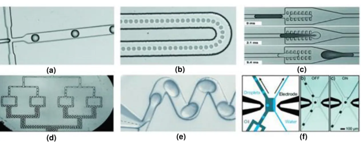
Figure 1.3. Droplet microfluidics operations: a) production; b) transport; b) fusion; d) fission; e)
mix; f) sort. Adapted from [23] and [22]. ... 6
Figure 1.4 Device geometries for droplet production: (a) regular junction; (b) head-on
T-junction; (c) T-junction for two species of droplets; (d) co-flow without flow-focusing; (e) co-flow with flow-focusing; (f) step-emulsification. Adapted from [20]. ... 6
Figure 1.5. W1/O/W2 emulsion stabilized by (a) soft materials (polymers or surfactants
represented by white and orange lines) or (b) solid particles; (c) and (d) represent possibilities of each phase with microfluidic devices by controlling the flow of fluids. ... 7
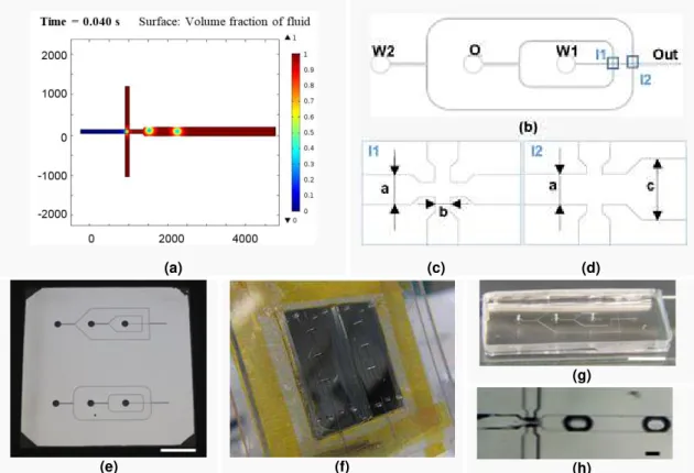
Figure 3.1. (a) Simulation of flow-focusing device of intersection 1 (I1) - More details in Appendix
2; (b) AutoCAD drawing of microfluidic device with round corners: inlets W1, O, W2 named after
fluid phase of required emulsion (Water 1, Oil, Water 2) and outlet named Out; (c) Magnification
of first Intersection, I1, same width for equal channels; (d) Magnification of second intersection, I2. Channel width dimensions: a = 100 µm, b = 50 µm, c = 200 µm. More details of dimensions in
Appendix 3; (e) Mask showing both geometries deseigned (scale bar = 1 cm); (f) Manufacture of PDMS devices: photograph showing SU-8 mold (120.2 ± 6.9 µm height) mounted between
PMMA plates with outlet needles inserted before PDMS curing; (g) Microfluidic device after bonding (scale bar = 1 cm); (h) Water/Oil test on I1: only water droplets were produced (scale bar
= 100 µm). ... 15
Figure 3.2. Immersion of PDMS substrates in acid solutions: (a) A and (b) B. Both acid
modifications form air bubbles from H2O2 decomposition; Modification A was applied into micro
channels: (c) air bubble (yellow cross) was injected in microfluidic channels through outlet against water (blue); (d) air blocks upper channel and HCl solution advances to left channel. White arrows
show fluids’ direction. It can be seen hydrophobic nature of PDMS by dark lines of water-based fluids against the walls. Scale bar = 200 µm. ... 16
Figure 3.3. (a) PVP film detaches from PDMS surface; (b) Modification D - when placed in water
for few minutes PVP dissolves; (c) Modification E– PVP film swells if cross-linked in UV 254 nm
for 24h; (d) PVP traveled for other channels during temperature process as shown by hydrophilic nature of wetting walls (yellow cross). Scale bar = 200 µm. ... 17
Figure 3.4. DWCA for one droplet of PDMS chemically oxidized with NaOH; 90º line in black.
xviii
Figure 3.5. (a, c, d, e, f) UV-Vis spectra recorded in 190-900 nm range of modified PDMS
substrates with thickness of 2.069 ± 0.027 mm. Respective modifications are indicated as follows: Concentration of NaOH solution in Molar (time of immersion in minutes), number of bilayers (time of immersion in minutes for each layer); (b) Photographs of PDMS 4 × 1 cm2 substrates correspondent to spectrum in (a). Note whitish color for “10M NaOH, 15min” photograph. ... 19
Figure 3.6.DWCA results for oxidation in 1M NaOH (15’) followed by adsorption of 1, 2, 3 BL for 5’ (blues) and 15’ (reds). Respective modifications are indicated as follows: Number of bilayers (time of immersion in minutes for each layer). Detailed WCA values in Appendix 8. ... 20
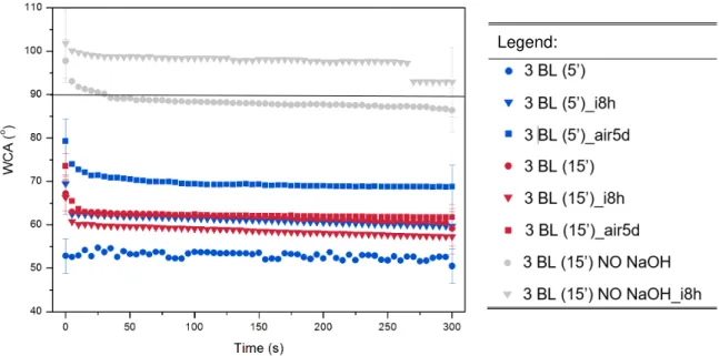
Figure 3.7.DWCA results for oxidation in 1M NaOH (15’) followed by adsorption of 3BL for 5’ (blue dots) and 15’ (red dots), with 8h immersion (X = i8h: triangles) in MilliQ and air storage for
5 days (X = air5d: squares). Comparison with non-oxidized samples (NO NaOH). Respective modifications are indicated as follows: Number of bilayers (time of immersion in minutes for each layer)_X. Detailed WCA values in Appendix 8. ... 21
Figure 3.8. FTIR spectrum in 4500-500 cm-1 range for (a) unmodified PDMS (black), and oxidized
PDMS with 1M NaOH (15’) and for extreme time of 24h as in [32]; (b) Detail of 3750-2700 cm-1
region; (c) Detail of 1750-1250 cm-1 region. Near 2350 cm-1 there is the peak of CO2 for 1M NaOH
(24h) resultant from absence of a baseline subtraction before that sample analysis. ... 22
Figure 3.9. Schematic diagram showing the oxidation of PDMS by alcohol, ester or carboxylic
acid groups. Based on [40]. ... 23
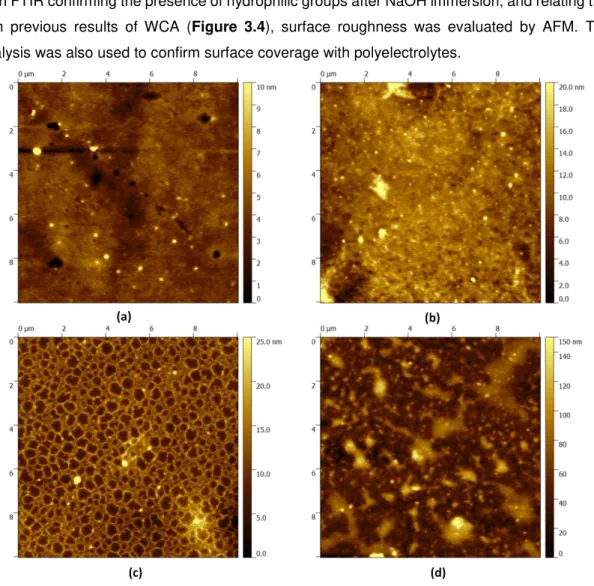
Figure 3.10. AFM 10 × 10 µm2 topographic images of (a) unmodified PDMS, rms = 1.15 nm; (b) modified PDMS in 1M NaOH (15’), rms = 2.54 nm; (c) with 3 BL (5’) deposition, rms =3.27 nm; (d) with 6 BL (5’) deposition, rms= 20.4 nm. 3D images in Appendix 9. ... 23
Figure 3.11. Microscope images of (a) hydrophobic unmodified microchannels: water droplets;
(b) 1M (15’), 1 BL (15’) injected in W2 and MilliQ as blocking solution injected in W1 and O: water droplets; (c) 1M (15’), 3 BL (15’) injected in Out and MilliQ in W1 and O: oil droplets; (d) Equal
modification to (b) injected in Out but with oil as blocking solution injected in W2: produces
droplets of the chemical solution; (e) Reaction between NaOH aqueous soution and oil stopped droplet production promoting chemical attack on left channel; (e) advancing oil contaminated outlet channel, limiting the modification. Water as colored liquid. Scale bar = 200 µm. ... 24
Figure 3.12. Without any vibration the fluids that are (a) controlled only on the Out (red) (b) start
flowing to channel behind I2, (c) eventually filling that channel with chemical solution. This turns
that channel also hydrophilic as seen in (d) and oil droplets form. Scale bar = 200 µm. ... 25
Figure 3.13. SEM micrographs of CaCO3 synthesized by precipitation reaction between 0.5 M
aqueous solutions of CaCl2.2H2O and Na2CO3at (a) 300 rpm, 30’; (b) 300 rpm, 2h; (c) 1200 rpm, 30’; (d) 1200 rpm, 2h. More in Appendix 11. ... 26
Figure 3.14. SEM micrographs of CaCO3 synthesized by precipitation reaction between 0.5 M
aqueous solutions of CaCl2.2H2O and Na2CO3 with 1200 rpm for 2h and [Mg]/[Ca] of (a, d) 2 (b,
xix
Figure 3.15. XRD analysis of (a) Calcite; (b) CaCO3 synthesized for different mixing speed and
time of reaction in absence of magnesium and; (c) Calcite and Aragonite; (d) CaCO3 synthesized
with magnesium inclusion with [Mg]/[Ca] of 2, 4 and 8 for a reaction at 1200 rpm during 2h. (a) and (c) from database: http://rruff.info/. ... 28
Figure 3.16. Photographs of W/O emulsion (a) immediately after emulsified and (b) 24h later.
Emulsion ID: 1 - PVA, 2 - PAA-Na, 3 - PVA + salts, 4 - PAA-Na + salts, 5 - CaCO3. ... 29 Figure 3.17. W/O emulsion stabilized with 10% (w/v) oleic acid in oil phase: (a) Photograph and
microscope image immediately after preparation and (b) 3 days after preparation. Other results in Appendix 15. ... 29
Figure 3.18. Photographs of O/W emulsion (a) immediately after emulsified and (b) 24h later.
Emulsion ID: 1 - PVA, 2 - PAA-Na with fluctuating oil droplets, 3 - PVA + salts, 4 - PAA-Na + salts, 5 - CaCO3 with depositing oil droplets. ... 30 Figure 3.19. Microscope images of oil droplets stabilized by CaCO3 particles for (a) initial time;
(b) 24h after preparation; (c) under crossed polarizer showing crystal birefringence and incomplete surface coverage. Notice dispersion in sizes. ... 30
Figure 3.20. Photographs of O/W emulsion (a) immediately after emulsified and (b) 7 days later.
Emulsion ID: 5 - CaCO3, 6 - [Mg]/[Ca] = 2; 7 – [Mg]/[Ca] = 4; 8 – [Mg]/[Ca] = 8. ... 31 Figure 3.21. Microscope images of oil droplets of emulsion 6 at (a) initial time; (b) after 7 days;
(c) under crossed polarizer showing birefringence. Other emulsions were similar and can be seen in Appendix 17. ... 31
Figure 3.22. (a) CaCO3 capsule before posterior mineralization; (b) after mineralization in ionic
solutions; (c) capsule grows triggered by an organic matrix; (d) capsule grows with aid of organic matrix. ... 32
Figure 3.23. CaCO3 (a) in 10 × PBS, disrupted at 24h (turbid solution); (b) formed agglomerates
in CaCO3 2.5 mM solution; (c) remained intact with lot of CaCO3 capsules in solution; (d) formed
agglomerates. ... 32
Figure 3.24. (a) Microscope image of collapsed droplets mineralized with “PVP 1300”; (b)
Crossed polarizer showing crystals; (c) SEM image after CaCO3 oil capsules dried in air- without
further mineralization – it can be seen a soft layer from oil between crystals; (d) TEM image of a CaCO3 particle/capsule. ... 33 Figure A1.1. Typical W/O/W double emulsion method to prepare microspheres containing protein
xx
to provide a hazardous condition inducing protein denaturation (I). Irreversible aggregation (H) between protein molecules can be formed if stabilizer or cryoprotectant is not added. Normally, microspheres made by double emulsion have a broad range of particle size distribution as well as different protein amount in each microparticle. In a release test, a burst release of protein at the initial period (b24 h) is mostly due to the protein release (K) from the proteinaceous film on the particle surface (D). With time, proteins are release from particles (J) by diffusion and degradation (L) of polymer (e.g., PLGA). Microparticle degradation cumulates acidic products inside particles (M), which further facilitates protein denaturation (N). Protein adsorption onhydrophobic polymer surface (O) often leads to incomplete release of protein drugs.”, quoted from
[49] ... 41
Figure A2.1. T-junction geometry with microfluidic channels of 50 µm width and depth. Simulation
parameters: no slip boundary condition; Qd = 20 µl/h; Qc = 50 µl/h. Results showed for times indicated in respective picture. ... 42
Figure A2.2. T-junction geometry with microfluidic channels of 50 µm width and depth. Simulation
parameters: wetted wall boundary condition; Qd = 20 µl/h; Qc = 50 µl/h. Results showed for times indicated in respective picture. ... 42
Figure A2.3. Flow focusing microfluidic device with inlet channels of 100 µm width and depth and
(a, b, c, d) an expansion chamber of 400 µm width with 90º walls (similar to step-emulsification). Simulation parameters: Qd = 6.66 µl/h; Qc = 7 x Qd µl/h; boundary condition: wetted wall (focusing
channel) = 3π/4; wetted wall (vertical walls of expansion chamber) = π. (e) Fluid becomes
unstable with increasing flow rate: Qd = 50 µl/h; Qc = 4 x Qd. µl/h. Results showed for times indicated in respective picture. ... 43
Figure A2.4. Flow focusing microfluidic device with inlet channels of 100 µm width and depth and
an expansion chamber of 200 µm width with 45º or 30º walls. Simulation parameters: Qd = 6.66 µll/h; Qc = 7 x Qd µl/h; boundary condition: wetted wall (focusing channel) = 3π/4; wetted wall (walls of expansion chamber) = π. No difference in droplet production was observed. Results
showed for times indicated in respective picture. ... 44
Figure A3.1. AutoCAD drawing with dimensions of microfluidic devices for W/O/W emulsion: (a)
with curve channels and (b) straight channels. Inlets have all same diameter and are named after emulsions phase. In (c) there is a magnification of first intersection, I1, and (d) the second
intersection, I2. “WX” refers to the width of respective channel and “LX” refers to the length of
marked path, with X dimension in micrometers. ... 45
Figure A3.2. AutoCAD drawing of PMMA plates: (a) top: drill and contour; (b) medium: open holes of devices’ size; (c) bottom: pocket for SU-8 mold. All measures in millimeters. ... 46
Figure A5.1. Flow confinement for outlet functionalization, where (a) chemical solution is injected
either by outlet (Out) or (b) by inlet W2, while blocking solution is injected in inlets O and W1; (c)
xxi
solutions are injected through Out, blocking solution through inlet O, inlet W1 is blocked and W2serve as outlet. Metallic part of 21G needles were used to connect tubes to inlets of the microfluidic device, and outlet tube was connected to a 26G and a 28G needle placed inside the device. ... 56
Figure A6.1. Photographs analysed for WCA of PDMS modified with (a, d, g, j, m, p) A; (b, e, h,
k, n, q) B; (c, f, i, l, o, r) C. Scale bar = 500 µm. ... 57 Figure A6.2. Photographs analysed for WCA of PDMS modified with (a, d, g, j, m, p) D; (b, e, h,
k, n, q) E; (c, f, i, l, o, r) F. Scale bar = 500 µm. ... 58 Figure A7.1. UV-Vis spectra in 190-900 nm range for modified PDMS with thickness of 0.869 ± 0.024 mm. Chemical treatment included 6 BL deposition of 5’ per layer after oxidation with 1M NaOH for 15’. (a) Polyelectrolyte solution without salt; (b) Polyelectrolyte solution prepared in 0.5M NaCl - absorbance seems to increase exponentially. ... 59
Figure A9.1. AFM 3D topographic images of (a) 2 × 2 µm2 unmodified PDMS; (b) 10 × 10 µm2
modified PDMS in 1M NaOH (24h) shows clearly increased roughness compared to (c) where
modification occurred for only 15’; (d) after 3 BL (5’), magnification in (e); (f) after 6 BL (5’)
deposition, magnification in (g). ... 61
Figure A11.1. SEM micrographs of CaCO3 synthesized by precipitation reaction between 0.5 M
aqueous solutions of CaCl2.2H2O and Na2CO3at (a) 300 rpm, 30’; (b) 300 rpm, 2h; (c) 1200 rpm, 30’; (d) 1200 rpm, 2h. ... 64
Figure A12.1. EDS for sample (a) 300 (2h) and [Mg]/[Ca] of (b) 2, (c) 4 and (d) 8. ... 65
Figure A13.1. Unsuccessful attempt to stabilize O/W emulsion with pre-synthesized CaCO3
xxiii
List of Tables
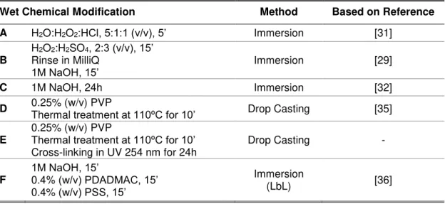
Table 2.1. Wet chemical modifications applied to PDMS substrates. For A), B), C) and F) at the
end of modification substrates were rinsed in MillliQ water and dried at RT. ... 10
Table 2.2. Prepared solutions for emulsions, volume ratios and identification. ... 12
Table 2.3. Mineralization aqueous solutions. ... 12
Table 3.1. WCA values obtained for PDMS with wet chemical modifications based on literature,
with example of photographs analyzed(scale bar = 500 µm). ... 16
Table 3.2. Legend with correspondent values of initial WCA. ... 18
Table A8.1. DWCA with and without oxidation with 1M NaOH for 15 minutes, and also with
immersion of 3 BL substrates for 8h, followed by 5 days storage in air. ... 60
Table A10.1. Approaches carried for turning the outlet channel of the microfluidic device
hydrophilic. ... 62
Table A10.2. Approaches carried, after hydrophilic modification, for turning the channel between
I1 and I2 hydrophobic. ... 63
Table A14.1. W/O emulsions: 1, 2, 3, 4, 5 microscope images and respective photographs. When
2 or more images are displayed for same emulsion, top image correspond to a sample of top of the emulsion, medium image of medium sample, and bottom image of sample extracted from the bottom (in same scale). ... 67
Table A15.1. W/O oleic acid emulsions (1, 5, 10 % (w/v)) microscope images and respective
photographs. When 2 images are displayed for same emulsion, top image correspond to a sample of top of the emulsion and bottom image of sample extracted from the bottom of the emulsion (in same scale). ... 68
Table A16.1. O/W emulsions: 1, 2, 3, 4, 5 microscope images and respective photographs. When
2 or more images are displayed for same emulsion, top image correspond to a sample of top of the emulsion, medium image of medium sample, and bottom image of sample extracted from the bottom (in same scale). ... 69
Table A17.1. O/W emulsion number 5, 6, 7, 8 microscope images and respective photographs.
When 2 images are displayed for same emulsion, top image correspond to crossed polarizer and bottom image without polarizer (in same scale). ... 70
Table A18.1. O/W PAA-Na emulsions (5 and 20% (w/v)) microscope images and respective
1
Objectives
One of the aims of this work is to develop a microfluidic device to produce monodisperse droplets directed to encapsulation. The development of such advanced system will allow the homogenous production of W/O/W emulsion, for future application in multifunctional particles for biomolecules encapsulation. For this type of emulsion, a selective microchannel surface modification is required. So, the first challenge is to achieve a stable wet chemical modification, and then apply it to closed microchannels.
Regarding encapsulation, this work takes biomimetic mineralization as inspiration to construct CaCO3 microcapsules. The influence of Mg2+ and organic matrices, namely PVA, PAA-Na and
3
1 Introduction
1.1. Biomimetics and Biomineralization
Nature presents uncountable examples of living organisms and structural materials with superior properties, which inspire the development of new advanced materials, devices and processes. This approach, known as biomimetics, is not new. Along with the development of micro and nanotechnology came the possibility to study the microstructure of the materials in natural organisms and to mimic these to develop new improved materials. [1] Some current popular examples of biomimetics include the lotus flower effect for water repellence, the gecko feet structure for high adhesion tape, insect eyes and wings microstructure for antireflective surfaces and sea shells and pearls for high mechanical strength composites and protective capsules. [1] Taking sea shells and pearls as examples, their formation either through biological or biomimetic controlled processes is referred to as biomineralization. This is a self–assembly process by which these living organisms produce mineralized hard tissues under physiological conditions. [2]
Mimicking Shells and Pearls: Calcium Carbonate
There is a variety of natural mineralized structures, like teeth and bone (composed of calcium phosphate minerals), sea shells, pearls and egg shells (composed of calcium carbonate), and others. [3] These mineralized structures are a ceramic–organic assembly that have calcium as common element and a complex multi-organic component that act as a glue. This last controls the size of minerals, their structure and morphology. [3] [4]
In particular, calcium carbonate appears in six different polymorphs, of which three are hydrated forms (calcium carbonate monohydrate, calcium carbonate hexahydrate and amorphous calcium carbonate) and three are anhydrous polymorphs (calcite, aragonite and vaterite in Figure 1.1).
Figure 1.1. SEM images of CaCO3 anhydrous polymorphs: (a) calcite; (b) vaterite; (c) aragonite;
(d) magnesium-doped amorphous calcium carbonate. [5]
(a) (b)
4
Regarding the regulating organic component in sea shells, there is a range of biopolymers involved, like acidic proteins with carboxyl groups, collagen, keratin, chitin and also silk fibroins. [6] [7] However, the function concerning each organic matrix, the cooperative role between them and the conjoin influence of the system specific parameters - like the concentrations of precipitants, presence of promoting or inhibitor ions as Mg2+, pH andtemperature - remains unclear. [4] [8]
Inspired by natural biomineralization, researchers have been using biomimetic methods (Figure 1.2) for mineral synthesis. Using additives to mimic the organic matrix role, various types
of crystal morphologies and sizes were synthesized. An extensive review can be found in reference [9]. Additives used include surfactants as SDS, synthetic polymers as PEG-b-PMAA, biomolecules as cellulose and proteins as DNA and BSA. The function of these additives is to interact with calcium ions, triggering CaCO3 heterogeneous (site specific) nucleation and
subsequent growth into nano or microparticles. [3] [4]
Figure 1.2. CaCO3 synthesis methods: (a) precipitation, (b) slow carbonation, (c) reverse (W/O) emulsion
and (d) CO2 bubbling method. The biomimetic method is represented by (a), (b) and (c). [9]
State of the Art Applications
Nowadays calcium carbonate is used as paper, plastic and paint additive to reinforce mechanical properties; in biomedical and pharmaceuticals for bone regeneration and drug delivery, and for biosensors used in food industry and environmental analysis. [7] [9]
In the biomedical field, particularly referring to the encapsulation for drug delivery, typically soft materials as polymers are used. However inorganic based capsules have been attracting attention due to their biodegradability, biocompatibility, simple preparation, low-cost procedures under mild conditions and simple triggering mechanisms by pH or mechanical force. [10]
Calcium-based minerals as CaCO3 and CaP are used to produce hollow shell-like capsules or
compact particles (beads) to encapsulate bioactive molecules using emulsion methods. [2] CaCO3 capsules were already produced with O/W emulsion using MAA polymer to trigger
mineralization and PVP in ionic solution to grow a thick shell [11]. Other methods include using pristine commercial CaCO3 particles with posterior mineralization by CO2 bubbling method [10]
or ionic solution [12] without the aid of polymers. These methods allow the encapsulation of hydrophobic substances as limonene [10]. To encapsulate hydrophilic biomolecules W/O/W double emulsions are employed [13], as in the synthesis of hydroxyapatite-graft-poly(D,L-lactide) capsules with mineralization carried in SBF [14].
5
As for compact mineral particles, those are used mainly as sacrificial templates to assemble polymeric capsules and to improve drug loading, as in BSA mineralization [15] or IBU loading on previously prepared CaCO3 particles [16]. But mineral particles are also used to directly protectbiomolecules as JEV, Ad 5 and yeast [3]. A detailed review can be found in [3] and [17].
Constructing biocompatible capsules offers protection to biomolecules against environmental degradation, allows a controlled release and reduces the risk of unwanted immune response. Traditional methods of encapsulation as spray and freeze-drying, crystallization, encapsulation into liposomes or polymeric particles, do not produce equal particles, which will result in heterogeneous properties. Besides that, encapsulated biomolecules are often exposed to high temperatures, gas–water interface or organic solvents, surfactants, and reactive cross-linking agents (Appendix 1). These factors can turn biomolecules unviable, for example in case of proteins it can lead to their denaturation.
So, the main challenge here is to control the properties of produced capsules, through homogenous production, regarding size, shape, morphology and biomolecule content, preserving the properties of encapsulated biomolecules during the process. [17]
One way to get that particle control and safe biomolecule manipulation is through microfluidics.
1.2. Microfluidics
Microfluidics is the science and technology of systems that manipulate small amounts of fluids in channels with dimensions of tens to hundreds of micrometers. These systems are generally characterized by a low Reynolds number, which makes all fluid flows essentially laminar. [18] The need of such field, was born from the necessity to carry out separations and detections with high resolution and sensitivity. Advantages of these systems include the use of very small quantities of fluids (sample and reagents) for fast and low-cost medical and environmental analysis, in a very precise environment (pH, ionic strength, concentration, etc.). [19]
Droplet Microfluidics
Manipulation of multiphase flows is one strength of microfluidic systems. If immiscible fluids are pumped into the device, it is possible to generate droplets with a discrete fluid dispersed in a second continuous phase fluid (Figure 1.3 - a). Then, through a number of operations, specifically
transport, fusion, fission, mix and sort it is possible to manipulate the droplets (Figure 1.3 – b to f). [19]
6
Figure 1.3. Droplet microfluidics operations: a) production; b) transport; b) fusion; d) fission; e) mix; f) sort. Adapted from [23] and [22].Device Geometries, Materials and Surface Chemistry
Typical geometries of these microfluidic devices include T-junctions, co-flow and step emulsification devices, as represented in Figure 1.4. [20]
Figure 1.4 Device geometries for droplet production: (a) regular T-junction; (b) head-on T-junction; (c) T-junction for two species of droplets; (d) co-flow without flow-focusing; (e) co-flow with flow-focusing; (f) step-emulsification. Adapted from [20].
For the T-junctions, the design and demands to manufacture the device as well as fluids manipulation are simpler. However, for larger flexibility in generated droplets, co-flow devices must be chosen, even though these require more complex channel geometries and more fluidic inlets. [20]
Besides device geometry, to achieve a stable droplet production and also the type of emulsion desired, the wettability of the walls of the microchannels is crucial. This factor depends on the material’s surface chemistry. Microfluidic devices are commonly made out of glass or silicon-glass, polymeric and metallic materials. [20] But for research purposes, it is important to minimize the technological and temporal effort using soft lithography techniques. This can be done with polymeric materials like PDMS, PMMA and PEEK, with the first being the most popular
(a) (b) (c)
(d) (e) (f)
(a) (b) (c)
7
due to its enhanced chemical resistance [24] and low fabrication cost when compared to others. [25] [26]Concerning the type of emulsion possible, since PDMS is hydrophobic, water droplets in an oil continuous phase will be generated. The importance of PDMS surface chemical modification, is to manufacture devices capable to produce complex emulsions for multifunctional particles, and
also prevent protein adsorption to channels’ walls in biological applications.
For this purpose, a variety of protocols can be found in literature to render PDMS hydrophilic and produce oil droplets instead. Some examples include UV radiation and O2 plasma treatments
which can lower PDMS water contact angle from 105º to 27°. By these methods hydrophobic recovery is commonly achieved in few hours, even though it has been reported hydrophilic stability up to 15 days. [27] Other methods include chemical vapor deposition, metal and metal oxide coatings, but these are time consuming and expensive, requiring specialized equipment and facilities. [28]
To solve these issues, wet chemical approaches rises as promising candidates since these are simpler and can be applied in closed channels, as many times as needed. For this goal, acid [29] [30] [31] and basic solutions [32] were used to change PDMS functional groups, turning its surface hydrophilic. More complex chemical treatments to the walls of microchannels include sol–gel routes to deposit thin glass coatings [33] [34], polymeric grafting with PVP [35] or acrylic acid coatings [33], and layer-by-layer deposition of polyelectrolytes. For this latter case a positively charged polymer and a negatively charged one are required, as PAH/PSS. [18] [36] The main drawback of this last method is that PDMS has to be oxidized first, to introduce hydroxyl groups capable to bond with polyelectrolytes, and this is mainly done during bonding process by O2 plasma, which is a clear disadvantage. [36]
Another issue is related to selective modification of microchannels, which with wet chemical approaches is achieved with flow confinement, controlling the flows of fluids only in certain channels. [33] [36] After that step, the microfluidic device should be capable of producing a double emulsion (Figure 1.5).
(a) (b) (c) (d)
Figure 1.5. W1/O/W2 emulsion stabilized by (a) soft materials (polymers or surfactants represented by white and orange lines) or (b) solid particles; (c) and (d) represent possibilities of each phase with microfluidic devices by controlling the flow of fluids.
In this work, a microfluidic system is designed, constructed and tested in terms of selectivity to fluids of emulsion for droplet production. However some challenges have to be overpassed, related to the wet chemical modification applied, to the selective functionalization of microfluidic channels, the emulsion compatibility with microfluidic device material and the stability of produced mineral capsules.
9
2 Experimental Section
2.1. Materials
Glass and silicon substrates (5 × 5 cm2, 0.7 mm thick, International Wafer Service), needles (21G
26G and 28G, Itec), 1 ml and 5 ml syringes (Injekt-F, BBraun), teflon tubes, MilliQ purified by E-POD (Elix).
SU-8 (Micro-Chem), PGMEA (Mw = 132.16 g/mol, assay > 99.5% Sigma-Aldrich),PDMS (Sylgard
184 Silicone Elastomer Kit, Dow Corning), IPA (Mw = 67-63 g/mol, assay ≥ 99.5 %, Fisher
Scientific), HCl 37% (Mw = 36.461 g/mol, Carlo Erba Reagents), H2O2 35% (Mw = 34.01 g/mol,
Valente e Ribeiro), H2SO4 (Mw = 98.08 g/mol, assay = 95-97%, Sigma-Aldrich), NaOH pellets
(Mw = 40 g/mol, ρ = 1.99 g/mL, Eka), PVP (Mw = 1300 000 g/mol, Sigma-Aldrich), PDADMAC
solution 20% in H2O (Mw = 100 000-200 000 g/mol, ρ = 1.04 g/mL, η = 60-180 cP @ 25 °C,
Sigma-Aldrich), PSS (Mw = 70 000 g/mol, ρ = 0.801 g/mL @ 25 °C, Sigma-Aldrich), CaCl2.2H2O
(Mw = 147.01 g/mol, assay > 99.0%, Sigma-Aldrich), Na2CO3 (Mw = 105.99 g/mol, assay ≥ 99.5%,
Sigma-Aldrich), MgCl2.6H2O (Mw = 203.3 g/mol, assay > 99%, Roth), PVA (Mw = 95000 g/mol,
95% hydrolyzed, Acros Organics), PAA-Na (Mw = 5100 g/mol, ρ = 0.55 g/mL @ 25 °C,
Sigma-Aldrich), PVP K15 (Mw = 6000 – 15000 g/mol, ρ = 0.6-0.7 g/mL @ 25 °C, ISP), oleic acid (Mw = 282.46 g/mol, assay = 97%, Fisher Scientific), commercial vegetable oil Alvolino used
without further purification or treatment.
Current lab equipment included scale (Kern), oven (Memmert), magnetic stirrer (Agimatic-N, P-Selecta), centrifuge (1-13, Sigma), flow controllers (model KDS-100-CE, KdScientific), ultrasonic processor (UP400S, Hielscher-Ultrasound Technology) and disperser (Ultra-Turrax, IKA).
2.2. Methods
COMSOL Multiphase Fluids Simulations
COMSOL Multiphysics® Software (version 4.4v, https://www.comsol.com) was used to simulate
droplet production capability of microfluidic devices with different geometries and wetting wall conditions. The protocol followed for simulation can be found in http://altsoft.co.kr/wp-content/uploads/2014/02/COMSOL_V4.4_heat.pdf (pages 28-48). Simulations were carried with default water and vegetable oil applying mass conservation. Time-dependent studies were carried from 0 to 0.160 s with 0.002 s step. More details of input data along with results in Appendix 2.
Development of Microfluidic Device for W/O/W Emulsion
Microfluidic Device Assembly
10
The optimized protocol and the equipment for manufacturing the mask and the SU-8 mold using soft lithography methods, and the PDMS microfluidic device, were provided by INESC-MN (Illustrated Run Sheets in Appendix 4). A brief experimental description follows.Mask was manufactured by coating a glass substrate with aluminum using Nordiko 7000, followed by patterning a deposited photoresist layer with Lasarray DWL 2.0 (Direct Write Laser system, Heidelberg). On a silicon substrate SU-8 was spin coated using WS-650MZ-23NPP/LITE spin-coater and patterned by contact UV lithography with previously fabricated mask. Three PMMA plates (10 × 10 cm2, two with 2 mm one with 4 mm thick) were micro machined using TAIG
Micro Mill (Super tech & Associates) controlled by a high frequency motor and the controlling software Mach2Mill CNC control program (ArtSoft Corporation, 2000-2004). With DesKAM2000 a certain function - contour, pocketing or drilling - was associated to each designed area in AutoCAD file (Appendix 3 - Figure A3.2)
For device fabrication, PDMS was prepared by mixing the base and the curing agent in 10:1 (w/w) ratio, which was then degassed and injected trough the top PMMA plate hole. A PDMS non-patterned layer was also prepared in a petri dish. Curing process was carried at 70ºC for 1h and 30 minutes in an oven. Microfluidic devices were assembled by bonding the two PDMS substrates (patterned and smooth) after corona discharge for 2 minutes per surface.
Post-Bonding Selective Channel Modification
Preliminary tests to evaluate surface modification were carried in PDMS substrates, prepared as previous mentioned on a smooth rectangular dish, and cut with 4 × 1 cm2. Prior to chemical
modification these were cleaned in ultrasound bath of IPA, at 30ºC for 30 minutes.
Different types of chemical solutions were tested namely acid, basic and polymeric. On the basis of the layer-by-layer method, a novel method was tested combining a first step of chemical oxidation with adsorption of polyelectrolytes. Details of prepared solutions and methods of chemical modification are in Table 2.1.
Table 2.1. Wet chemical modifications applied to PDMS substrates. For A), B), C) and F) at the end of modification substrates were rinsed in MillliQ water and dried at RT.
Wet Chemical Modification Method Based on Reference
A H2O:H2O2:HCl, 5:1:1 (v/v), 5’ Immersion [31]
B
H2O2:H2SO4, 2:3 (v/v), 15’
Rinse in MilliQ
1M NaOH, 15’ Immersion [29]
C 1M NaOH, 24h Immersion [32]
D 0.25% (w/v) PVP
Thermal treatment at 110ºC for 10’ Drop Casting [35]
E
0.25% (w/v) PVP
Thermal treatment at 110ºC for 10’
Cross-linking in UV 254 nm for 24h Drop Casting -
F
1M NaOH, 15’
0.4% (w/v) PDADMAC, 15’
0.4% (w/v) PSS, 15’
Immersion
11
A more detailed study was conducted for modification F (Table 2.1). The influence of severalparameters was evaluated, in particular NaOH solution concentration (1, 3, 6, 10 M) and time of immersion (5 and 15 minutes), time of immersion in each polyelectrolyte solution (5 and 15 minutes) and number of bilayers adsorbed (1 to 3). To study duration capabilities of the modification, hydrophilic character of substrates was evaluated in three distinct times. In this case immediately after modification, after 8h immersion in MilliQ (with 100 rpm agitation) and also following 5 days storage in air.
For hydrophilic outlet channel modification, the setup in Appendix 5was used. This included flow controllers, syringes, tubes, and needles. As a blocking solution water or oil were used and as wet chemical treatment modification F (Table 2.1) was applied, with 1 or 3 polyelectrolyte bilayers.
Mineralization Applied to Emulsions: CaCO
3Capsules
Mineralization of CaCO
3To study the influence of mixing speed and time of reaction in CaCO3 crystal size, a modified
protocol of [16] for synthesizing CaCO3 microparticles was used. Aqueous solutions of
0.5 M CaCl2.2H2O (A) and Na2CO3 (B) were prepared. Equal volumes of A and B were rapidly
mixed, with solution B added to solution A. The reaction took place for mixing speeds of 300 and 1200 rpm, during 30 minutes and 2h.
To study the influence of magnesium in CaCO3 synthesis, aqueous solutions of 1, 2 and
4 M MgCl2.6H2O (C) were prepared and added to solution A in equal volume. Solution B was
added as before, with equal volume to total volume of solution A and C together. This time, a mixing speed of 1200 rpm was used for a 2h reaction.
After precipitation reaction, CaCO3 minerals were triple centrifuged and washed at 10000 rpm for
2 minutes, and finally dried at RT.
Simple Emulsions
With the future goal of a double W/O/W emulsion, simple emulsions were studied to evaluate how to stabilize W/O and O/W interface, through mineralization, adding polymers or both. To try stabilization by CaCO3 minerals, both pre-synthesized and in-situ precipitated crystals were used.
For first case, protocol similar to [10] was followed (volumes and mass fractions were maintained). Briefly 0.2 g of CaCO3 pre-synthesized particles were dispersed in 4 ml of MilliQ. A volume of
0.4 ml of vegetable oil was added and the mixture was sonicated with cycle value of 1 and amplitude of 100% for 1 minute.
For emulsions with polymers and in-situ precipitation of CaCO3, the ratio between two phases
was maintained at 1:10 (v/v) for W/O and O/W.
12
Table 2.2. Prepared solutions for emulsions, volume ratios and identification.Solution ID Aqueous solution of Volumes Emulsion ID
A 1% (w/v) PVA VW = VA 1
B 1% (w/v) PAA-Na VW = VB 2
C 1% (w/v) PVA in 0.5 M CaCl2.2H2O VW = VC + VD
VC = VD 3
D 1% (w/v) PVA in 0.5 M Na2CO3
E 1% (w/v) PAA-Na in 0.5 M CaCl2.2H2O VW = VE + VF
VE = VF 4
F 1% (w/v) PAA-Na in 0.5 M Na2CO3
G 0.5 M CaCl2.2H2O VW = VG +VH
VG =VH 5
H 0.5 M Na2CO3
I, J, K 1, 2 and 4 M of MgCl2.6H2O
VW = VG +VI, J, K +VH
VG + VI, J, K = VH
VG = VI, J, K
6, 7,8
Because of immediate precipitation reaction between calcium containing solutions and carbonate containing solutions, for cases where salts were involved, CaCl2.2H2O aqueous solution was
added first to glass, followed by oil volume fraction and in last place Na2CO3 aqueous solution.
The mixtures were rapidly sonicated with same parameters as before. The tip of sonicator was washed with acetone between samples preparation.
For emulsion 5, 6, 7, 8, since these were respective to main goal of producing mineral capsules
with diameter similar to that of microfluidic outlet channel, Turrax was used with 3000 rpm for 1 minute, to obtain larger particles.
Continuous Mineralization
Emulsion stabilized by CaCO3 particles (Table 2.2 - 5) was subjected to a posterior crystallization
process, based on protocol in [11] and [14]. Emulsion 5 was incubated in a 0.1% (v/v) ratio in
different solutions. Incubation was carried for 3 days with reposition of aqueous medium every 24h as indicated in Table 2.3.
Table 2.3. Mineralization aqueous solutions.
Ionic Solutions 0.5% (w/v) PVP in B
ID A B C D
10 × PBS 2.5mM CaCl2.5mM Na2.2H2O
2CO3
High Mw
“PVP 1300” PVP K15 Low Mw
Refreshed
with A B B B
13
2.3. Characterization
Profilometer
Using Alpha Step 200 profiler (Tencor Instruments, INESC-MN) six height measures were taken of SU-8 mold in the 6 inlets available. SU-8 height result is presented as mean value with standard deviation.
WCA
For preliminary tests WCA was registered with a Casio EX-F1 Exilim Pro using the setup described in [38]. Photographs were taken after 30 seconds of placing a 5 µl droplet in the PDMS substrate. The photograph was converted to grayscale and contrast was enhanced using Adobe Photoshop Elements 8.0. Images were analyzed with Image J (version 1.48v, http://imagej.nih.gov/ij/)) software using Drop Analysis- DropSnake plugin, which allows an active contour to shape the drop. In this study, 12 to 16 dots per droplet were used, 6 droplets per substrate were dispensed and photographed, and each image was measured 6 times. WCA results are presented as mean value with standard deviation by propagation of uncertainty. For modification F (Table 2.1), dynamic water contact angle measurements were performed using
an OCA15 contact angle measuring instrument (DataPhysics Instruments GmbH, Filderstadt, Germany). Water microdrops (volume ≈ 5 μl) were generated with an electronic micrometric
syringe and deposited on the sample surface. A film was recorded during 300 seconds at a rate of 2 fps, starting from the moment of the drop deposition. WCA was determined by fitting the shape of the drop to the Young-Laplace equation, which relates interfacial tension to drop shape. A total of six drops were dispensed and each drop was placed in a different region of the sample. The results correspond to the mean value with standard deviations. Image acquisition, analysis and contact angle determination were performed using the SCA15 v.4.3.12 and v.4.3.16 software (Dataphysics Instruments GmbH, Filderstadt, Germany). All measures were taken immediately after chemical modification and substrate drying at RT, except for substrates stored for 5 days in air.
UV-Vis spectroscopy
Oxidation effect and polyelectrolyte film growth was monitored in T90+ UV/VIS Spectrometer, PG Instruments Ltd, with UVWin software. Spectrums were acquired in 190-900 nm range, with an air baseline and an unmodified PDMS spectrum registered before different modifications.
FTIR
To elucidate about surface modification, FTIR was performed on a Thermo Nicolet 6700 spectrometer in ATR. The equipment was operated from 4500 to 525 cm -1 with a 2 cm-1 step. A
14
AFM
To evaluate the effect of modification F (Table 2.1) on PDMS roughness and surface coverage,
images of PDMS unmodified and modified surfaces were acquired using Asylum Research MFP-3D Standalone AFM system. This equipment was operated in alternate contact mode, using commercially available Si probes (Olympus AC160TS) with a resonant frequency of 300 kHz and a spring constant of 26.1 Nm-1 at 1 Hz scan rate. Areas of 10 x 10 µm2 and 2 x 2 µm2 were
scanned and images plane fitted. 3D images were also generated.
Optical Microscopy
Optical microcopy for general monitoring was conducted with CETI microscope coupled with PC-Ocular Camera (Type 049002-VGA by Meade Instruments (Rhede, Germany), connected to
a laptop for live recording using Window Movie Maker 12 software
(http://windows.microsoft.com/pt-pt/windows-live/movie-maker). This setup was used to monitor microfluidic channels selective modification.
For studies on emulsions, images were acquired with Olympus Optical Microscope (U-TV0.5XC-3, Tokyo, Japan) coupled with the light source Olympus- KL2500 and using the micro-imaging software, Olympus Stream Basic. Emulsions were analyzed immediately after preparation and for a time where alterations were observed. Sample preparation required to place a small sample volume in a microscope slide, without coverslip in case of mineralized capsules.
XRD
Samples of CaCO3 obtained by precipitation reaction with and without magnesium, were
characterized by X-ray diffraction (X'PerPRO, PANalytical) with CuKα radiation (λ = 1.5418 Å) at 45 kV and 40 mA, with the linear detector X'Celerator. The diffraction pattern was collected in Bragg-Brentano configuration in 2θ ranging from 20° to 90° at a scanning rate of 0.0167º.
SEM-EDS
Images of synthesized CaCO3 minerals and capsules were obtained using the scanning electron
microscope of high resolution EOL JSM-7001F/Oxford 250/HKL INCA Energy, at Microlab-IST. A drop of the diluted sample was placed into the sample holder using a carbon tape. The solvent was left to evaporate at RT and a very thin layer of gold-palladium was deposited on top of the sample to enhance the detection.
TEM
15
3 Results and Discussion
3.1. COMSOL Simulations and Microfluidic Device Assembly
Results from simulation can be consulted in Appendix 2. Some main conclusions follows. For water droplets production, a wetted wall condition had to be introduced in the simulation using a contact angle of 90º with walls (hydrophobic channels). If a smaller angle was chosen, the droplets slide through microchannels or appeared as plugs (elongated). To produce spherical droplets, water contact angle with the walls, as well as flow rates, have to be taken into account. With this information, it is possible to predict that to produce oil droplets instead, hydrophilic/lipophobic channels are required. Comparing between different geometries, it was easier to use flow-focusing device to produce spherical droplets, with channel after intersection with 45º walls and dimensions similar to droplet size (Figure 3.1 - a). Using protocols provided
by INESC-MN, and considering microscope equipment available, it was possible to scale down dimensions in half compared to the ones used for simulation. Figure 3.1 shows the process for
development of the device from simulation to drawing and finally the assembly and test.
(a) (c) (d)
(e) (f)
(g)
(h)
16
3.2. PDMS Surface Properties Characterization
Preliminary Studies on Modifying PDMS Surface
Water Contact Angle
For this work the outlet channel of the microfluidic device has to be hydrophilic. Thus a selective surface modification has to be found to be applied in closed channels. Table 3.1 summarizes the
chemical solutions tested and both measured and expected WCA. Images analyzed are in Appendix 6.
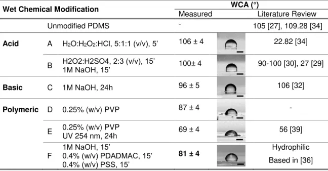
Table 3.1. WCA values obtained for PDMS with wet chemical modifications based on literature, with example of photographs analyzed (scale bar = 500 µm).
Wet Chemical Modification WCA (°)
Measured Literature Review
Unmodified PDMS - 105 [27], 109.28 [34]
Acid A H2O:H2O2:HCl, 5:1:1 (v/v), 5’ 106 ± 4 22.82 [34]
B H2O2:H2SO4, 2:3 (v/v), 15’1M NaOH, 15’ 100± 4 90-100 [30], 27 [29]
Basic C 1M NaOH, 24h 96 ± 5 106 [32]
Polymeric D 0.25% (w/v) PVP 87 ± 4 -
E 0.25% (w/v) PVP UV 254 nm, 24h 69 ± 4 56 [39]
F 1M NaOH, 15’0.4% (w/v) PDADMAC, 15’
0.4% (w/v) PSS, 15’
81 ± 4 Hydrophilic
Based in [36]
- Acid solutions
During modification A and B, air bubbles formed by reactants interfered in a way PDMS was little
or nothing affected, so WCA remained unchanged. This modification couldn’t be selectively applied to microchannels because air bubbles destabilized the fluids flows (Figure 3.2).
(a) (b) (c) (d)
17
- Basic solutionsIn modification C, oxidation was expected and WCA obtained is similar to the reported value in
literature, with PDMS maintaining its hydrophobicity. This seems contradictory. Further FTIR and AFM analysis may help to clarify this issue.
- Polymeric solutions
PDMS does not have functional groups to attract non-ionic PVP, so drop casting was chosen to
deposit a thin PVP film followed by temperature treatment at 110ºC for PVP grafting (Figure 3.3 - a). In Figure 3.3 - b and c, comparing modification D and E, one can see that
cross-linking prevented PVP dissolution. This is the reason that explains a higher WCA comparing
D to E recipe, with WCA value between the one of PVP film (68°) and PDMS. With PDMS
absorbing for wavelengths lower than 250 nm, it is impossible to use E recipe in closed channels.
Besides that, in microfluidic device it is also impossible to control PVP solution flow when subjected to heat (Figure 3.3- d), and so a controlled selective modification cannot be achieved.
(a) (b) (c) (d)
Figure 3.3. (a) PVP film detaches from PDMS surface; (b) Modification D - when placed in water for few minutes PVP dissolves; (c) Modification E– PVP film swells if cross-linked in UV 254 nm for 24h; (d) PVP traveled for other channels during temperature process as shown by hydrophilic nature of wetting walls (yellow cross). Scale bar = 200 µm.
Since for oxidation in microfluidic device, with closed channels, only modification C is possible of
being applied, in test F a new approach is proposed. This combines chemical oxidation stabilized
with adsorption of oppositely charged polyelectrolytes. Results obtained for just 1 BL (a pair of adsorbed polyelectrolytes: PDADMAC and PSS) render PDMS hydrophilic.
Proposed Method for PDMS Selective Surface Modification
Based on previous results for modification F (Table 3.1), a deep study on the chemical oxidation
of PDMS followed by surface modification with polyelectrolytes was performed.
Oxidation by NaOH
- Dynamic Water Contact AngleIt has been described the role of NaOH to oxidize the surface of PDMS. Common oxidation processes referred in Introduction are known to introduce –OH, –COH, –COOH hydrophilic
groups by –CH3 substitution. [40] This experiment was set to find a condition where PDMS turned
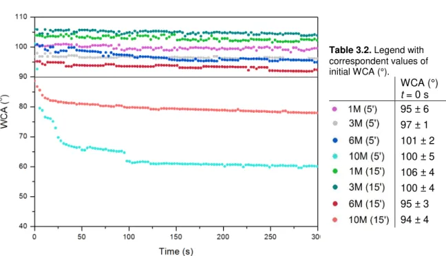
hydrophilic in shorter time possible. It was verified that WCA could change in a dramatic way over time for some substrates, so a 5 minute video was recorded for one of the droplets. Figure 3.4
18
Table 3.2. Legend with correspondent values of initial WCA (°).WCA (°)
t = 0 s
95 ± 6 97 ± 1 101 ± 2 100 ± 5 106 ± 4 100 ± 4 95 ± 3 94 ± 4
Figure 3.4. DWCA for one droplet on PDMS chemically oxidized with NaOH; 90º line in black. Oxidation treatment indicated as follows: Concentration of NaOH solution in Molar (time of immersion in minutes).
It can be assumed that deviation for results in Figure 3.4 are the same registered for initial time
(t = 0 s). No correlation of WCA is observed between NaOH concentration and time of immersion.
Also, WCA results for time zero and for when the angle became stable don’t always match (see
sample 10M (5’) vs. 10M (15’)). A reason for all of that may be the dissolution of non-cross-linked chains of PDMS in such oxidizing solutions, which creates heterogeneity in surface modification. Associated to this, low molecular weight PDMS chains can migrate from the substrate to surface which decreases the available hydrophilic polar groups. [27] A less plausible reason is hydrophobic recovery, which is a phenomenon vastly reported in literature. This process refers to recombination of newly introduced –OH groups and reversal of hydrophilic PDMS to hydrophobic in few hours. [27] However, WCA analysis was conducted immediately after substrate drying, which took only a few minutes, and therefore that hypothesis is not probable.
For the application required it is more significant to analyze transient PDMS behavior, which refers to analyzing WCA when stable. In that case it was possible to render PDMS surface hydrophilic with 10M NaOH immersion for 5 or 15 minutes. Even though it could be expected that a prolonged
immersion time resulted in a lower WCA, that didn’t happen. WCA results for these samples may be explained by the possible breakage of PDMS chains resulting in increased surface roughness. There must be a competing event between oxidation and surface roughness, the first contributing to lower WCA and the second to increase it. If this is true, it explains that a more hydrophilic substrate was obtained for immersion in 10M NaOH only for 5 minutes instead of 15, since a prolonged time in such concentrated solution may have increased a lot the roughness. As for
19
Oxidation Followed by LbL of Polyelectrolytes
- UV-Vis Spectroscopy
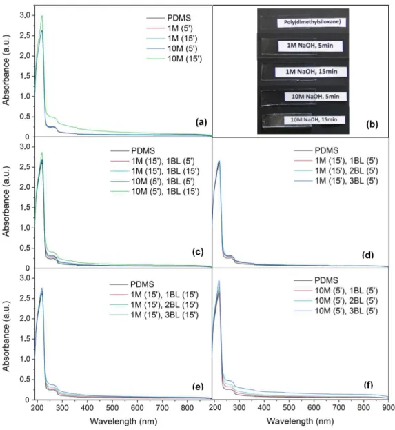
UV-Vis spectroscopy of samples was used to set best conditions for hydrophilic PDMS modification, keeping its optical properties (transparency) unchanged as possible. This was monitored by absorbance increase in PDMS samples when modified with NaOH and deposition of polyelectrolytes for 1, 2, or 3 BL, which is possible since PSS has a maximum absorbance at 224 nm. [41] The results are in Figure 3.5. Note that 1BL means an adsorbed pair of a positive
(PDADMAC) and negative (PSS) polyelectrolyte.
Figure 3.5. (a, c, d, e, f) UV-Vis spectra recorded in 190-900 nm range of modified PDMS substrates with thickness of 2.069 ± 0.027 mm. Respective modifications are indicated as follows: Concentration of NaOH solution in Molar (time of immersion in minutes), number of bilayers (time of immersion in minutes for each layer); (b) Photographs of PDMS 4 × 1 cm2 substrates correspondent to spectrum in (a). Note whitish color
20
From Figure 3.5 - a and b it can be seen that at extreme conditions - higher concentration andlonger time of immersion, 10M (15’) - PDMS substrate turns white, which excludes such modification to be carried. To select conditions for polyelectrolyte adsorption study, it was chosen as oxidation parameters immersion in less concentrated solution for longer time (1M NaOH for 15 minutes), and in higher concentrated solution for less time (10M NaOH for 5 minutes). The goal here was to verify if similar results could be obtained in shorter times using a concentrated NaOH solution.
As shown in Figure 3.5 - c,for 10M (5’), 1 BL (15’) there’s a greater increase in absorbance which
eliminates that condition as a viable option for modification, since more layers need to be deposited, which would correspond to even higher absorbances.
For the remaining three hypothesis, 3 BL were deposited. It can be noted that increasing time of immersion leads to an increase in absorbance, related to the thickness of film adsorbed, as shown by Figure 3.5 - d vs. e. Also, using 10M NaOH solution even for short time, resulted in higher
absorbances (Figure 3.5 - f), even when polyelectrolyte adsorption occurred for only 5 minutes.
This means that thicker layer of polyelectrolyte was adsorbed. However this last substrate turned white, and this condition was eliminated. This sets as best conditions the immersion in 1M NaOH for 15 minutes, with polyelectrolyte adsorption for 5 or 15 minutes per layer. As for absorbance variation in general, which increases only slightly between bilayers, it was reported elsewhere a variation of less than 0.1 magnitude, similarly to this study. [41] It is noticeable in literature about this matter, that has been referred along this work, the use of polyelectrolyte solutions with salt (as NaCl).This factor lowers polymers solubility in water contributing for a thicker layer deposited (Appendix 7). This in turn results in less transparent PDMS and for this case was not considered.
- Dynamic Water Contact Angle
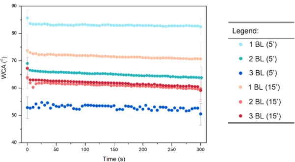
DWCA was measured for 1, 2 and 3 BL deposited for 5 or 15 minutes. Results are in Figure 3.6.
Figure 3.6. DWCA results for oxidation in 1M NaOH (15’) followed by adsorption of 1, 2, 3 BL for 5’ (blues) and 15’ (reds). Respective modifications are indicated as follows: Number of bilayers (time of immersion in minutes for each layer). Detailed WCA values in Appendix 8.
![Figure 3.8. FTIR spectrum in 4500-500 cm -1 range for (a) unmodified PDMS (black), and oxidized PDMS with 1M NaOH (15’) and for extreme time of 24h as in [32]; (b) Detail of 3750-2700 cm -1 region; (c) Detail of 1750-1250 cm -1 region](https://thumb-eu.123doks.com/thumbv2/123dok_br/16697870.743893/46.892.158.749.308.602/figure-ftir-spectrum-unmodified-oxidized-extreme-region-region.webp)