“A modified debugging infrastructure to assist real time fault injection campaigns”
André V. Fidalgo
1,2, Gustavo R. Alves
1, José M. Ferreira
2anf@ isep.ipp.pt [email protected] [email protected]
1
Instituto Superior de Engenharia do Porto
2
Faculdade de Engenharia da Universidade do Porto
Abstract
Fault injection is frequently used for the verification and validation of the fault tolerant features of microprocessors. This paper proposes the modification of a common on-chip debugging (OCD) infrastructure to add fault injection capabilities and improve performance. The proposed solution imposes a very low logic overhead and provides a flexible and efficient mechanism for the execution of fault injection campaigns, being applicable to different target system architectures.
1 Introduction
In safety critical applications dependability is of fundamental importance. Dependable systems are designed to handle errors that originate from software or hardware faults and recover from them, while maintaining acceptable operating conditions. The possibly destructive nature of a failure and the long error latencies impair identifying the cause of failures in field operation and in the normal time that it takes for a failure to occur. To identify and understand possible errors, it is desirable to experiment on an actual device as to better study and improve its dependability. This approach can be applied either in the development phase, where models or prototypes are used, or on the deployment phase if faults can be deliberately injected in useful time without damaging the equipment. This experiment-based approach requires knowledge of the system architecture and behavior, and especially of the mechanisms implemented to provide tolerance to faults, errors or failures, i.e. the events leading to a service failure on microprocessor based systems [1]. Specific instruments and tools must be used to induce these hazards and monitor their effects. In the case of microprocessor based systems, access to the internal resources is of utmost importance. Many of today’s microprocessors provide such access through dedicated built-in debug circuitry, which is often designated as on-chip debug (OCD). Using these OCD infrastructures for fault injection purposes is an efficient solution for verifying and validating fault tolerant designs. This paper proposes to upgrade these infrastructures by adding specific functionalities to improve the fault injection process.
The rest of the paper is organized as follows: the next section gives an overview of fault injection methodologies used on microprocessor based systems; section 3 presents the system used for our case study and our proposal to modify existing OCD infrastructures for enhanced fault injection support; section 4 presents the experimental results obtained so far and finally section 5 discusses these results and lays the basis for future work.
2 Fault Injection Methodologies
A mean to achieve dependability is the use of fault-tolerant components. In this sense fault injection can be used to:
Identify design or implementation faults.
Verify & validate and fault tolerance capabilities. Estimate how often failures will occur and evaluate the
consequences of such failures.
A fault injection mechanism must be adapted to its target system and must include the following components: A fault injector: the device used for the actual fault
injection and that requires some type of communication channel with the target to be able to affect it. This channel may be non-physical and in some techniques it may be bi-directional returning some type of information to the fault injector. The fault injector is normally capable of injecting different types of faults according to a given fault model, defined beforehand. A workload generator: outputs commands and data to
the target system. These can be signals, synthetic code, benchmarks or complete applications.
A data collector: retrieves the necessary information from the target system to characterize the fault injection and the target response. An associated data analyzer is used when the collected data requires processing and in most cases this analysis is performed off-line, at a later time.
Fault injection is normally structured in campaigns, each being composed of a series of experiments during which the target system runs (a specific workload is activated) and a specific fault (or set of faults) is inserted at specific trigger conditions. The target system behavior is monitored and information is recorded as comprehensively as necessary and possible, as to later understand and evaluate the effects of the inserted faults. Existent microprocessors fault injection techniques are commonly classified in three broad groups, namely: Simulation based fault injection.
Software based fault injection (SWIFI)
Physical fault injection (sometimes designated as hardware based).
Simulation based fault injection is mostly used in the early phases of a design when the target system exists only in model format. To use this technique it is necessary: a model of the target itself, normally in some HDL format; the necessary simulation tools to insert faults; adequate processing capabilities to run the simulation [2].
Software based fault injection consists of reproducing at a logical level the errors originated by physical faults using software commands already available on the target device. SWIFI allows the injection of errors on all resources accessible by software like registers, program and data memory, most peripherals and some timers [3].
Physical fault injection is a more realistic approach in the sense that it tries to replicate real world faults. All physical techniques perform an actual fault insertion on the circuit or emulate their immediate consequences (errors) through internal or external action. Access to the circuit elements is usually performed either trough specific hardware equipment [4] or using debug and test infrastructures included on the target chip [5]. Physical fault injection may also be performed without a direct connection between the fault injector and the system under test, either through laser [6], heavy-ion radiation or electromagnetic fields [7].
Simulation techniques can be used on an early phase of development but are often time-consuming and may lack fault coverage as they are intrinsically dependant on the quality of the available model. SWIFI techniques are less expensive but require modifications to the running code which in fact modifies the target system and faults can only be inserted in the resources accessible by software. Physical fault injection usually allows a better representation of real world faults but it is usually more expensive and sometimes less controllable.
The hardest part of fault injection in microprocessors is how to access those internal elements where faults are more probable, generally the memory elements and communication buses, without disturbing the running applications. OCD infrastructures provide a solution for this problem as they allow access to most microprocessor elements and are designed for use without taking any resources from the processor. The functionalities provided by the OCD vary between implementations, but usually include run control, breakpoint support, code tracing and access to memory and internal registers. In most implementations, the microprocessor must be halted and placed into a special debug mode during OCD interactions. OCD also requires some external hardware, to support the communication between the chip and a debugger host. OCD infrastructures are generally based on different architectures and access ports, normally requiring specific hardware and often with proprietary parts. Each microprocessor developer generally has its own name for this technology, such as BDM, OnCE, and MPSD, and other simply add debug capabilities to existing JTAG test ports. Debuggers are available from multiple sources normally as a combination of hardware and software tailored for a specific target system.
OCD infrastructures provide access to internal resources in parallel with the target hardware and running software, being an excellent mechanism for modifying register and / or memory values (i.e. insert faults) and subsequently retrieve the data necessary for results analysis. An added value is the non-intrusive nature of this form of fault injection, as it requires no modification to the target system. As a technological solution, the major problem with OCD is the lack of a consistent set of capabilities and
a standard communications interface across processor architectures.
An industry consortium called NEXUS has been working on the establishment of a standard for OCD. It's formally called IEEE-ISTO 5001 [8]. If widely adopted, it may be possible to use the same remote debugger to access the core of multiple different processors and to use a common set of debugging features for all of them. This standard is still in a proposal phase, but already presents an interesting possibility for the development of common fault injection methodologies for the verification & validation of dependable microprocessor-based systems. Most fault injection techniques that use OCD rely on halting the processor, either by the use of external control signals or using breakpoints, and subsequently modify the targeted registers or memory locations to emulate a fault. The usual approach involves a host machine running the fault injection campaign and a debugger accessing the target infrastructure.
A microprocessor compliant with class 2 or above of the NEXUS standard must provide trace information on-the-fly and may allow memory access through the OCD with the processor running. Experimental work has been done in our research group and in the DISCA-UPV [9] using real-time fault injection on a MPC565 based system, which is the most widely used NEXUS compliant microprocessor. The obtained results confirmed most of the expected potentialities and simultaneously identified some shortcomings both in fault triggering and performance. It proved possible to insert faults in memory space on-the-fly and then use the trace information gathered as an effective mean to analyze program flow, before and after the actual fault activation. However, both NEXUS compliant debuggers used [10] [11] communicate with the PC running the fault campaigns either through Ethernet or USB connections, which imposes a critical limitation on real time access on high performance systems. As the PC manages most debugging functions, it proves difficult to read memory contents and write back a modified value before the initial data is actually overwritten by the application running on the target system. The magnitude of the problem depends of the running application and memory position targeted, but in some cases it is impossible to insert the desired fault without halting program execution. Fault activation is also a difficulty as even when reading trace data without halting the processor, this information is not readily available, as it must reach the host machine before it can be acted upon and this delay can be measured in milliseconds or more, which effectively prevents its use for fault triggering. A solution to counter these limitations would be either speeding-up the debug data flow or moving the decision making elements nearer to the target device.
3 Case Study 3.1 Target System
Two areas where it is possible to improve the fault injection capabilities in microprocessor systems with built-in debugging mechanisms are the debugger and the OCD itself. In an effort to cover the most ground we opted
to conduct experiments on both areas and compare the obtained results. The use of NEXUS compliant devices benefits from the useful debugging features defined in the standard and increases the area of immediate applicability of the developed concepts and solutions. As neither the actual commercial NEXUS debuggers nor the compatible CPUs are easily modifiable, we selected an alternative microprocessor core where a NEXUS compliant OCD could be implemented. A customized debugger was also required, as available devices require specific libraries for each target. We opted for developing the OCD and the debugger as VHDL modules, aiming to keep them simple, both to be easily portable and to maintain a high level of compatibility with different target architectures. In this way a complete proof-of-concept solution can be tested and the requirements for its migration to existent or in development systems will also be evaluated.
As the microprocessor target we selected the cpugenerator [12] building tool, which is publicly available through opencores [13]. This tool allows the automatic creation of 4, 8, 16 or 32 bit RISC microprocessor cores. It is possible to configure several microprocessor parameters like bus type, interrupt support and memory configuration. Depending on configuration, this microprocessor is expected to run between 23 and 138 MHz on a Xilinx[14] Virtex2 device, when synthesized with ISE 7.1i.
The OCD infrastructure was designed to be compliant with the NEXUS 5001 standard proposal. As there is no mandatory implementation, it is based on the infrastructure present on the MPC565 microcontroller, which is a well-documented compliant device. The version actually implemented on our target system is Class-2+ compliant and is also configurable to adapt itself to the target system, being compatible with different CPU configurations, with only minor adjustments.
The debugger consists of one controller module and two memory banks for data input and output. An external clock is required as a source for the clock signals used for communicating with the OCD. As the debugger main purpose is fault injection campaign managment, it is built with reduced support for direct control, the emphasis being on executing scripted commands and reacting automaticly to specific messages or signals from the OCD. This last possibility is an important feature that is lacking in most other debuggers, as it is not required for commom debugging operations. At this phase the debugger supports only the NEXUS messages actually implemented on our OCD, with all messages sent from the debugger being preloaded on a memory bank that acts as a script for each debugging session. Two messages have special meaning to the debugger, being interpreted as internal commands, not sent to the NEXUS port. One allows for a delay interval before sending the next message and the other instructs the debugger to wait for an signal from the NEXUS port before sending the next message. The messages output from the OCD are also stored on a separate memory that can latter be used by an external tool for program flow analysis and fault effects diagnosis The data provided by the trace plus eventual error messages plus the knowledge of the running application make it possible to reconstruct the exact program flow. A typical fault injection scenario is presented on Figure 1,
where boxes #1 and #2 may represent simulation modules, physical devices or parts of the same FPGA.
PC Debugger Target System OCD #1
USB / Ethernet NEXUS
#2
Figure 1 – Debugger and Target System
The target application for testing is the matrix_addFT program, which is a fault tolerant version of a matrix adder application. The fault tolerance is achieved by duplicating each arithmetic operation and then comparing the obtained results, with any difference triggering an error detection routine. Although not as powerful as hardware fault tolerance, this solution allows for some degree of dependability without modifications to the hardware, at the cost of memory space and some performance penalty.
The NEXUS standard defines a minimum set of debugging features, the interface port and the communication protocol. The implemented features include all common OCD features plus access to memory in real time. The interface with the outside world is made using the AUX port option, which provides two message data buses for OCD data input and output along with independent clock and control signals. Two additional event pins allow halting the processor and exact timing for watchpoint / breakpoint signaling. An additional (RSTI) pin is used for resetting the OCD infrastructure.
The communication protocol is message based, with each message consisting of a six-bit header that indicates the message purpose and additional variable length data packets if required. The infrastructure accepts command messages and outputs response and status messages. All mandatory messages were implemented as well as additional optional (developer-defined) messages, as allowed by the NEXUS proposed standard, used for internal register access and OCD configuration.
The implemented OCD infrastructure is divided in three main modules and two bus access modules as seen on Figure 2. The thinner arrows represent the several control and status signals and the thicker arrows represent data and trace information flow. The FI module represented is not included in the original OCD as it gives form to the OCD-FI version explained further ahead on this paper.
The MQM (Message Queuing and Management) module is both the NEXUS message handler and the OCD controller. It translates all debugging operations into messages and vice versa, manages the message queues and provides the necessary control signals to the other modules. The message queues are implemented using FIFO (First-In First-Out) memory blocks and in the case of an overflow, an error message is sent from the MQM module to the debugger, via the NEXUS port.
The RCT (Run Control & Trace) module is responsible for CPU run control and bus snooping. It receives commands from both the MQM and RWA modules and outputs trace data and watchpoint hit signals. This module controls the CPU core clock and the signals required to identify branch and exception occurrences on the running application. The RCT module will enter DEBUG mode when requested by the MQM module, a breakpoint is hit or on reset, if configured to do so. In DEBUG mode all OCD resources are available although the application execution is halted. The RCT also includes several configuration registers, including OCD status and breakpoint conditions. It is possible to use up to two instruction and one data breakpoint and both types can be activated at the Nth occurrence of their trigger condition. Additionally a watchpoint may be generated in the same manner as either type of breakpoint. The bus snooper is used to monitor data and instruction bus activity and the RCT module uses this information for breakpoint / watchpoint generation and program trace. Program trace is performed using branch trace messaging as defined in the NEXUS 5001 standard, counting executed instructions and signaling on taken branches or exception occurrences. The RWA (Read & Write Access) module is used to access both OCD registers and CPU resources (memory and registers). A register (RAW_reg) is used to store the data and address of the next read / write operation, as this information takes several clock cycles to be transmitted by the MQM module. This register is loaded whenever a message requesting a read or write operation is received. In normal conditions the actual operation is executed immediately on the rising edge of a signal sent from the MQM module after the RAW_reg register update is complete. Conflicts in RAM access are handled by the bus master with the OCD taking priority on access by default. As inputs and outputs are handled by the processor as directly mapped addresses it is possible to access those resources in the same manner as the processor would. An access to a CPU core internal resource requires the RCT module to be in DEBUG mode.
The bus snooper and bus master modules are responsible for interfacing with the microprocessor buses. The complete OCD infrastructure provides a common set of debugging features and interface options that can be adapted to different target systems, and upgraded to support additional features or elements.
3.2 Fault Injection Module
The selected fault model is used in most common fault scenarios for microprocessor based critical systems [15] and consists of single bit-flip faults at random memory elements at also random moments during the application
execution. The actual fault trigger can be any instruction occurrence of the running application, covering the entire execution time. The fault location can be any resource accessible for writing through the OCD, including memory, internal registers and stack. The fault injection campaigns are randomly generated by an external tool and then described as a script with the necessary messages to be sent to the OCD infrastructure, both for configuration and data collection.
Any fault injection campaign must be initialized by loading the application into memory and setting up the OCD environment as required by the faults to be inserted. If the fault is to be inserted on an internal register or the stack, a breakpoint replaces the watchpoint, and the EVTO signal is replaced by a message acknowledging the entry on DEBUG mode following a breakpoint hit. Additionally, an extra message must be sent to restart the application execution after the fault injection process. The choice of starting the processor in debug mode or in execution mode depends on the instruction address that triggers the fault injection procedure. If it cannot be assured that enough time is available for setting up the required OCD registers then the processor must start in debug mode.
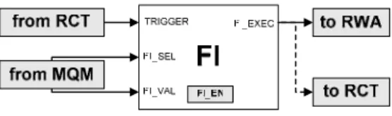
Although the debugger allows a fast reaction to trigger condition(s), the actual fault insertion still requires the transmission and decoding of at least one complete message. The On-Chip Debug and Fault Injection (OCD-FI) concept proposed on this paper consists of a hardware module to insert faults on the occurrence of the trigger condition(s) without further commands from the debugger and it is implemented within the OCD circuitry reusing some of the already implemented debugging functions. It requires the implemented OCD to execute write operations by pre-loading one or more registers and the write operation itself to be executed on the activation of a specific control signal. Additionally the OCD must internally signal breakpoint or watchpoint occurrences. The Fault Injection (FI) module is represented in Figure 3. It monitors the watchpoint or breakpoint signal(s) so that, when enabled, it can activate a fault injection action.
Figure 3 – Fault Injection Module
The input signals FI_SEL and FI_VAL are used to access the FI_EN register, which enables and configures the FI module. The TRIGGER input prompts the execution of the FI operation. The output signal (FI_EXEC) is used to activate a memory write operation in order to insert a single bit-flip fault at a given address. This approach requires that both the data value to be written and the respective memory address have to be determined beforehand and preloaded in the OCD register (RAW_reg) that is used for data writing. To do this, a previous analysis of the running application is necessary to determine the target memory position contents at the injection instant. In this manner it is possible to determine
the value that should be stored so that a single bit-flip is caused on the target. The required address and data vector must be downloaded to the OCD infrastructure prior to the watchpoint occurrence, and the RAW_reg register must not be rewritten until the actual fault activation. Once the fault is inserted, the FI module disables itself and all the OCD resources can then be used normally. All the fault injection set up can be done with the target processor running normally, but the fault activation may only take place after this set up is performed. The program trace is not affected and operates normally before, during and after the fault injection process, reacting exactly as if a “real” fault was inserted.
For internal register or stack faults it is only necessary to add a breakpoint with the same address as the watchpoint, to assure the processor is halted at the fault injection instant.
From the messages output by the NEXUS port it is possible to reconstruct the program flow and diagnose fault effects verifying if the fault was acknowledged by the error detection routine, and after the application runs its course it is possible to use the OCD to check if all results are correct.
Two extra and optional NEXUS messages are used, one to enable and configure the FI module and another to set up the address and data values for the actual fault injection. Fault triggering can be done using either a breakpoint or a watchpoint. The watchpoint option allows the injection of faults without stopping the target system but can only be used for memory, as access to internal register requires the system to be halted. The signal used for fault activation can also be used for exiting the DEBUG mode and restart program execution, as represented in Figure 3 as a dotted line. In this form the OCD-FI infrastructure allows the insertion of faults in all resources mapped in the OCD, with a minimum time delay.
Dependability verification it structured into fault campaigns, each one defining a set of fault injection executions where a specific fault location and trigger is selected. In each execution the processor is reset and the application runs from start. As stated before, the FI module can be programmed prior to the application start or in runtime, the only limiting factor being the fault activation instant. To determine the target memory value at the moment of the injection beforehand it is possible to either use the knowledge of the running application code or perform a prior faultless execution up to the fault triggering instant and use the OCD to read the relevant memory contents. The fault trigger condition is selected beforehand from the executed application code. These fault campaigns can then used for experimental evaluation of the target device fault tolerant characteristics and preliminary results were used to analyze the fault injection procedure itself.
4 Experimental Results
The target system, the debugger, the fault injection module and the different memories were designed as VHDL models using the ISE 7.1i development environment and simulated using the Modelsim 6.0a simulation engine. Two CPU configurations were used
differing only in terms of bus width, both including full interrupt support and internal stack. Both configurations include separate ROM and RAM banks on the target system, the first for storing the program code and the later for application data.
The fault campaigns were structured as follows:
All experiments part of the same campaign target either RAM or internal registers.
As a simplifying step the fault campaigns are also divided between those where the fault is activated before setting up is possible and those where this can be done with the processor running.
The OCD is configured once at the beginning of the campaign, with the configuration depending on the fault injection target (memory or registers).
A campaign is loaded into memory and the experiments are executed sequentially.
The instruction address that triggers each fault injection is randomly generated from the actually executed ROM space and each target memory position is also randomly selected from the used RAM space.
The results are retrieved after all the experiments are complete, their analysis being performed externally to check if the final results are correct and if the fault was detected by the fault tolerance routine.
Each set of fault campaigns was executed on each of the configurations and repeated using both the original OCD and the OCD-FI infrastructure. After simulating several fault campaigns the following conclusions, relative to the fault injection processes, were reached:
The OCD-FI infrastructure does not affect the maximum microprocessor clock frequency, being possible to use the same frequency for all clocks.
Each infrastructure requires a minimum number of MCKI clock cycles for system set up prior to each fault injection operation and for the writing operation itself, as represented in Table 1. Set up time supposes that all configuration registers are already set up (prior to the fault injection campaign) and writing time is measured from the watchpoint hit to the writing instant of the intended value into memory.
OCD OCD-FI
CPU Set up Writing Set up Writing
8 bit 13 14 28 2
32 bit 14 21 36 2
Table 1 – Fault Injection Delay (in CLK cycles) If targeting internal microprocessor registers, execution
must be halted for only 2 additional clock cycles if using the OCD-FI infrastructure, which increases slightly the time interval required to run each fault campaign. If using only the OCD for register access, the time
interval during which the processor must be halted is 2 clock cycles higher that the time required for memory writing.
When using only the OCD and memory as the target, some experiments return meaningless results because the CPU writes on the memory cell being targeted before the fault is inserted. This did not happen with the OCD-FI.
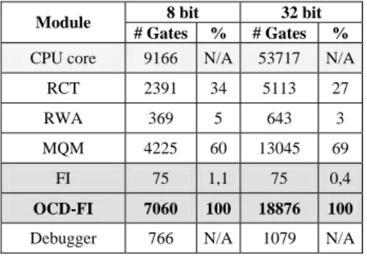
The number of equivalent gates for each module and each CPU configuration is given by Table 2. The Bus Snooper and Bus Master modules gate counts are included in the RCT and RWA counts, respectively.
8 bit 32 bit Module
# Gates % # Gates %
CPU core 9166 N/A 53717 N/A
RCT 2391 34 5113 27
RWA 369 5 643 3
MQM 4225 60 13045 69
FI 75 1,1 75 0,4
OCD-FI 7060 100 18876 100
Debugger 766 N/A 1079 N/A
Table 2 – Area Overhead
From the above values it is possible to confirm that the logic overhead of the FI module on the OCD infrastructure is minimal. It is also possible to see that a simple debugger tasked only with fault injection campaigns management and results storage requires comparatively little space on a programmable device. The area of the OCD itself it is somewhat large for the implemented CPU cores, as the used configurations are rather simple in terms of register and instruction support. This effect is less notorious as the CPUs increase in complexity, because the OCD area is mostly dependant of the size and complexity of the communication buses.
5 Conclusions and Future Work
From the available results it is possible to conclude that the proposed OCD-FI infrastructure is an efficient mechanism for verifying and validating the fault tolerance characteristics of microprocessor based systems. The FI module main advantage is the extremely fast reaction time and when compared with other alternatives, it provides an efficient methodology for fault injection, both in terms of reusability, resource coverage, performance and cost. If the necessary HDL modules are available the OCD-FI, can be used for injecting faults in the simulation phase, prototyping phase or on the final device if the FI module makes it that far. Faults can be inserted on most CPU resources with a minimum time delay, allowing non-intrusive and fast fault injection campaigns. The achieved performance is better when targeting memory space and when the faults are not injected early in the application execution, and if this is the case, fault campaigns can be executed almost as fast as it takes to run the target application, without stopping it.
The compliance with the NEXUS proposed standard provides a common basis for development and enhancement of the proposed methodology. In this sense, the OCD-FI concept can be extended to any NEXUS compliant microprocessor and other architectures, providing a very low logic overhead derived from the fact that the more complex functions are performed by the OCD infrastructure. As this is already required for debug purposes, the added FI module provides considerable advantages with little area overhead. It should be easy to add to most devices, and with eventual modifications it is
a lightweight solution for most microprocessor architectures. As an added feature, the debugger may be included into the same programmable device as the target system therefore assuring the best performance and reducing necessary resources and associated costs, the only limitation being the availability of memory blocks for data storage.
As a downside, we have the need of an adequate OCD infrastructure and the required availability of both the OCD and the target CPU in some type of HDL description. If injecting faults on a physical device, an external debugger is also required along with an adequate communication channel.
Actually we are working on experimenting with different scenarios and on extending the OCD-FI concept to different microprocessor architectures including versions supporting hardware fault tolerance mechanisms.
References
[1] “Basic concepts and taxonomy of dependable and secure computing”; A. Avizienis, J.C. Laprie, B. Randell, C. Landwehr; IEEE Transactions on Dependable and Secure Computing, Volume 1, Issue 1; Jan 2004.
[2] “Comparison and application of different VHDL-based fault injection techniques”; J. Gracia, J.C. Baraza, D. Gil, P.J. Gil; IEEE International Symposium on Defect and Fault Tolerance in VLSI Systems; San Francisco, USA; Oct 2001.
[3] “Experimental evaluation of a COTS system for space applications”; H. Madeira, R. R. Some, F. Moreira, D. Costa, D. Rennels; International Conference on Dependable Systems and Networks; Bethesda, USA; June 2002.
[4] “Experimental Validation of High-Speed Fault-Tolerant Systems Using Physical Fault Injection”; R. J. Martínez, P. J. Gil, G. Martín, C. Pérez, J. J. Serrano; Seventh IFIP Working Conf. Dependable Computing for Critical Applications: DCCA-7; San Jose, USA; Jan. 1999.
[5] “Evaluation of the Thor Microprocessor Using Scan-chain-Based and Simulation Based Fault-Injection”; P. Folkesson, S. Svensson, J. Karlsson; 8th European Workshop on Dependable Computing (EWDC-8); Goteborg, Sweden; April 1997.
[6] “A Technique for Automated Validation of Fault Tolerant Designs Using Laser Fault Injection (LFI)”; J. R. Samson , W. A. Moreno, F. J. Falquez; 28th Annual International Symposium on
Fault-Tolerant Computing; Munich, Germany; June 1998.
[7] “Application of Three Physical Fault Injection Techniques to the Experimental Assessment of the MARS Architecture”; J. Karlsson, P. Folkesson, J. Arlat, Y. Crouzet, G. Leber and J. Reisinger; 5th IFIP Working Conference on Dependable Computing for Critical Applications; Urbana-Champaign, USA; September 1995.
[8] “The Nexus 5001 Forum Standard for a Global Embedded Processor Interface version 2.0”, IEEE-ISTO 5001 2003.
[9] “INERTE: Integrated NExus-Based Real-Time Fault Injection Tool for Embedded Systems”; Yuste P., de Andrés D., Lemus L., Serrano J. J., Gil P. J.; The International Conference on Dependable Systems and Networks; San Francisco, USA; June 2003.
[10] www.isystem.com/Products/Emulators/iC3000/ [11] www.lauterbach.com
[12] Giovanni Ferrante, “CPUGEN 2.00”, 2003. [13] www.opencores.org
[14] www.xilinx.com
[15] “How to characterize the problem of SEU in processors & representative errors observed on flight”; R. Velazco, R. Ecoffet, F. Faure; 11th IEEE International On-Line Testing Symposium; Saint Raphael, France; July 2005.