ABSTRACT: The software in satellite applications has become increasingly larger, more complex and more integrated, so its veriication and validation require exploration of new approaches. In this paper we present a Model-Based Testing (MBT) approach applied to the Communication Module of the ITASAT-1 university satellite. The models are Finite State Machines (FSM) representing the software behavior. In order to manage the dificulties to model the software behavior the approach employs the Conformance and Fault Injection (CoFI) testing methodology associated with the JPlavisFSM tool in the real context of a satellite’s critical software. The former advises the modularization of the modelling into different types of behavior into different FSMs, while the latter integrates several FSM-based methods to derive test cases, provides facilities to design and to check properties of the models and computes metrics. The main result of this case study was the evaluation of the drawbacks on the design of the testing models supported by CoFI and JPlavisFSM. The models, test sets, metrics with the application of our approach applied to the Communication Module are presented. The paper discusses the beneits as well as the points requiring new researches.
KEYWORDS: Finite state machine, Model-based testing, Test-case generation methods, Testing methodology.
FSM-Based Test Case Generation
Methods Applied to Test the
Communication Software on Board the
ITASAT University Satellite: A Case Study
Arineiza C. Pinheiro1, Adenilso Simão1, Ana Maria Ambrosio2INTRODUCTION
he increasing development of university satellites has allowed researchers to experiment new approaches in space area. In traditional satellite development, experimental methods are usually avoided to prevent risks and cost increase, whereas university satellites open an opportunity to explore new approaches using a real system (Alencar, 2013).
he sotware for satellite applications has become increasingly more complex, as it includes more functions and is more integrated. he development of satellite-related sotware usually requires a series of rigorous tests, along with all the satellite development phases. he development tendency of this kind of sotware points out the use of formal models for the designing and testing. To adopt formal models, such as the Finite State Machines (FSMs), not only does it beneit the identiication of ambiguities and gaps in the requirements (Morais and Ambrosio, 2010; Morais, 2011; Pontes et al., 2012), but it also makes the automatic generation of test cases feasible (Ambrosio
et al., 2005; Romero et al., 2012) by applying the vast theory of automatic test case generation.
he speciication of test cases for embedded sotware in satellites should take into account characteristics such as: real-time requirements, integration of technologies and fault tolerance mechanisms. he occurrence of failures in this kind of sotware may cause large losses, so they should be thoroughly tested using systematic and rigorous approaches, in which
1. Instituto de Ciências Matemáticas e de Computação/USP – São Carlos/SP – Brazil 2.Instituto Nacional de Pesquisas Espaciais– São José dos Campos/SP – Brazil.
Author for correspondence: Ana Maria Ambrosio | Instituto Nacional de Pesquisas Espaciais | Avenida dos Astronautas, 1.758, CEP: 12.227-010 –São José dos
Campos/SP | Brazil | Email: [email protected]
various testing techniques are combined to exercise diferent aspects of the system.
he Model-based Testing (MBT) is an approach that reduces cost with the automation of test cases generation and with the reuse of models created during the sotware designing and testing activities; besides that, it provides high fault detection and traceability. In MBT, the test designer can specify the test model using diferent modeling notations, such as FSMs, Labeled Transition Systems (LTS), Uniied Modeling Language (UML) state machines, etc. FSM is a formal modeling technique, adopted due to its rigor and simplicity. FSM-based testing has been studied for several decades (Moore, 1956; Chow, 1978) and it has still presented contributions (Simão et al., 2009; Simão and Petrenko, 2010; Yin et al., 2010; Pedrosa and Moura, 2010; Hierons and Ural, 2010; Simão et al., 2005) such as a tool that integrates diferent FSM-based methods into a single sotware product named PLAVIS (PLAtform for Sotware Validation & Integration on Space Systems); similar work is given in Santiago
et al. (2008).
In MBT, supporting tool plays an essential role, since the cost of building the models for testing only should be balanced by the possibility of generating and executing larger test suites (Utting and Legeard, 2007). However, the difficulties still remain to build the models. In our work, we have applied the Conformance and Fault Injection (CoFI) methodology (Ambrosio, 2005) in order to guide the tester to create the models associated with the JPlavisFSM tool (Pinheiro, 2012). CoFI was irstly proposed to lead a tester to understand the problem well enough while creating a set of FSMs representing normal and abnormal behavior of sotware on-board a satellite. It deines detailed steps to apply FSM-based testing tools, in a systematic way and it has been applied in several cases (Ambrosio et al., 2007; Pontes et al., 2009; Anjos et al., 2011; Mattiello-Francisco et al., 2013). JPlavisFSM tool comprises not only four methods to automatically generate test cases starting from a given speciication in FSM but also the Mutation Testing technique (Fabbri et al., 1994), that allows the adequacy evaluation of a test cases set.
This paper presents a case study in which the CoFI methodology and the JPlavisFSM tool are combined to test the Communication Module of the ITASAT-1 satellite (Sato et al., 2011). All the steps applied to design the models have been illustrated. We employed the JPlavisFSM tool to the test case generation, exploring all the FSM-based methods available. The main result of this case study was the
identification of the drawbacks to create the testing models that is the key activity to successfully apply MBT techniques to satellite-related software. On the modelling work, we found that the previous knowledge on the testing methods theory had facilitated the modelling process, which took 16 days only. The length of time to understand the system under test, to do the modeling and to generate the test cases accounted for 33 days. We did not evaluate how the models impacted on the quality of the tests, as the tests were not executed against the implementation of the Communication Module software, because the implementation was not finished before the conclusion of this work. However, we evaluated the quality of the test sets by mutation analysis applied to FSM.
The remainder of this paper presents the background, the CoFI and the JPlavisFSM tool, the case study, and inally, discusses the MBT applicability and the conclusions.
BACKGROUND
In this section, we introduce the main concepts necessary for understanding the results presented in this paper.
FINITE STATE MACHINES
Finite State Machines (FSMs) have been widely used for modeling reactive systems, ranging from simple protocols to complex embedded systems (Lai and Leung, 1995). Among the main advantages of FSMs, there are the solid theoretical background, the expressiveness power and the existence of numerous methods to generate test cases. FSMs are hypothetical machines composed of states and events, which correspond to transitions between the states. A transition is associated to two kinds of events: input and output. When an input event occurs in a given state, the FSM responds with an output event and may move to another state (Gill, 1962).
Formally, a Mealy FSM is defined as a tuple M = (S, s0, X,
Y, D, λ, δ), where: S is the nonempty finite set of states; s0 is the initial state (s0∈S); X is the nonempty finite set of input symbols;
Y is the nonempty finite set of output symbols; D ⊆ (S × X) is the specification domain; λ : D → Y is the output function; and
δ : D → S is the transition function.
Given state s and input x, the transition (s, x) is defined if (s, x) ∈D. An input sequence α = x1x2…xk is defined at state
s if there exists a sequence of states s1, s2, …, sk+1, so that s =
s1 and (si, xi) ∈D, δ (si, xi) = si+1, for 1 ≤i≤k. The set of input sequence defined at state s is denoted ΩM(si). The output and transition functions are extended to defined input sequences in the usual way; given a state s and the empty sequence
Є, we have that δ (s, Є) = s and λ (s, Є) = Є; given input sequence α and input x, we have that δ (s, αx) = δ (δ (s, α), x) and λ (s, αx) = λ(s, α)λ(δ (s, α), x). A set of input sequences is initialized if it contains the empty sequence. An input sequence α separates states s and s’, if λ(s, α) ≠ λ(s’, α). A set of sequences is an identifier for state s, denoted Id(s), if for each state s’ ≠ s, there exists a sequence in Id(s) which separates
s and s’. A set containing one identifier for each state is
harmonized, if for each pair of state s and s’, there exists an input sequence α∈Id(s) ∩Id(s’) which separates them. An input sequence α is a Unique Input/Output Sequence for state
s, denoted UIO(s), if {α} is an identifier for s.A set of input sequence W is a characterization set for each pair of state s
and s’, if there exists an input sequence in W which separates them. A preamble for state s is an input sequence α, so that
δ(s 0, α) = s, i.e., it takes the FSM from the initial state to s. A state cover is a set containing preambles for each state. A transition cover is a set P of input sequences, so that, for each defined transition (s, x), there are α and αx in P, where
α is a preamble for s.
he FSM M is defined over X. Based on this definition, some structural properties in FSM, which are important for test case generation methods, are listed:
• Completely specified – an FSM is completely specified, or complete if all states (S) have a transition for each input event from the set of input symbols (X), so that
D = (S × X). Otherwise, the FSM is partially specified, or partial;
• Strongly connected – an FSM is strongly connected if for every pair of states (si, sj) there is a path that leads si to sj, i.e., there is some input event sequence that performs a path of transitions with source in si and destination of sj. If all other states can be reached from the initial state, the FSM is initially connected;
• Deterministic – an FSM is deterministic when there is only one transition with a particular input event from any state thatallows transition to a next state. Otherwise, the FSM is nondeterministic;
• Equivalent – one state si is considered equivalent to sj if there is no input event sequence which, when executed from the respective states, generates a diferent output sequence; • Reduced – an FSM is reduced if there is no pair of
equivalent states. Otherwise, it is unreduced.
FINITE STATE MACHINE (FSM)-BASED TESTING
In the context of FSM-based testing, a finite sequence of input events is a test case, or just a test. A set of test cases is a finite set of sequences, so that there are no two sequences α and
β ∈T, where α is a proper prefix of β. (here are two sequences
α and β, α is preix of β, if α≤β, such as αω = β, to any ω. And,
α is a proper preix of β, if α < β, such as αω = β).
Given two FSMs M and I; two states s from M and t from I are distinguishable if there is an input sequence γ∈ΩM(s) ∩ ΩI(t), called separating sequence, so that the same input event sequence generates different output sequences for both FSMs, i.e.,
λ (s, γ) ≠ λ (t, γ). Two FSMs I and M are distinguishable if their respective initial states are distinguishable.
A fault domain Γ(X) is the set of all possible implementations of M defined over the set of input symbols X. Similarly, Γn(X) denotes the set of all FSM defined over the set of input symbols
X with at most n states. he test set T is said n-complete, or just
complete, for the specification M if for all I∈Γn(X), so that I
is distinguishable from M, there is at least one sequence α∈T
that produces diferent output sequences when applied to M
and I in the respective initial states. In other words, a test set is complete when it is possible to distinguish the specified FSM with n states from all other distinguishable FSM with the same set of input symbols and at most n states.
a / 1
b / 1 b / 1 b / 0
b / 0
a / 0
s0 s1
s2 s3
a / 0
a / 0
he main objective of the FSM-based testing is to compare a reduced FSM modelM with n states to an implementation
of the FSM model, which is assumed to be represented by an unknown FSM I. When a reduced FSM M which represents the correct version of the specified FSM is compared to FSM
I, the following faults may be revealed (Chow, 1978): • Output Error: I and M difer in the output of a transition; • Transference Error: I and M difer in the final state. When
the inal state achieved in both FSM is diferent ater applying a test case;
• Transition Error: it is the general term for output or transference error;
• Missing States: I has fewer states than M;
• Extra States: I has more states than M.
Several methods have been proposed for generating set of test cases which guarantee that the implementation does not contain any of the above listed faults, that is, which are complete regarding these faults. he completeness of the generated test case is proved by showing that no faulty implementation FSM would pass the test cases. he main diferences among them are the cost to generate the sequences and the efectiveness (the power of the test cases to detect faults). One of the irst methods to be proposed was the W (Chow, 1978), which is considered a precursor of the area, since most of the following methods are based on it: UIO (Sabnani and Dahbura, 1988), UIOv (Vuong et al., 1989), Wp (Fujiwara et al., 1991), HSI (Petrenko et al., 1993) and SPY (Simão et al., 2009).
MUTATION TESTING
he Mutants Analysis is one of the most popular criteria of Defects-based testing, which aims at deriving test requirements from knowledge about typical mistakes made by designers or developers. Mutation Testing is a testing technique that can be widely employed as a way of evaluating the test cases generated. he criteria can be used as:
• Black-box testing, when we consider the speciication as a test artifact, or
• White-box testing, when the artefact considered is the source code. In this context, the test artifact could be represented formally by a model, as FSM.
he Mutants Analysis consists of assessing the adequacy of a test set T for the test artifact P. First, you run the test set
T against P. If a fault occurs, a defect was found. Otherwise, it is assumed that some defects already exist but cannot even be detected.
he next step is to derive one or more products from the original artefact P, which gives the new products P1, P2, ..., Pn, also called mutants of P. Mutants are generated from mutation operators, which are dependent on the programming language and determine what types of syntactic changes can be made in the artefact. he mutation operators’ aim:
• Inducing simple syntactic changes based on the typical mistakes made by developers, such as changing the value of a constant, or
• Forcing certain test goals, such as performing each node or arc of the product (Delamaro et al., 2007).
The test set T is executed against each of the mutants generated. The main objective is to “kill” all mutants. It is expected that, due to the changes made, the mutants have diferent behavior from the original product, featuring a defect.
Occasionally, when the artifact is a source code, a mutant and the original product can still have the same result for any test case in the set. In these cases, the tester has to check the code and determine whether there is equivalence between the products. If so, the mutant is called as equivalent. The equivalence between programs is an undecidable problem and, therefore, there is no automated solution to the problem and the manual intervention of the tester is necessary. However, when the product is a model, there is no equivalency problem, because it could be determined automatically due to the formality of the FSM.
After the mutants’ execution and equivalence analysis, the mutation score is calculated. he aim is to determine the adequacy of test cases used in a range from 0 to 1, providing a quantitative measure of how eicient the test set is in revealing the diference between the mutant and the original product. he mutation score ms(P, T), to product P and the set of test cases T is calculated as:
DM(P,T)
ms(P,T)=
M(P)-EM(P)
where: DM (P, T): number of mutants killed by T; M (P): total number of mutants generated from P, and EM (P): number of generated mutants that are equivalent to P (Delamaro
he mutation score is obtained from the ratio between the number of mutants killed by the set T and the number of mutants that could be killed, given by the diference between the total number of mutants generated and the number of mutants classiied as equivalent.
THE JPLAVISFSM TOOL AND
THE CONFORMANCE AND FAULT
INJECTION METHODOLOGY
his section presents the main features of the JPlavisFSM tool and the CoFI methodology which were combined to guide the creation of FSMs, representing the system’s behavior.
JPLAVISFSM TOOL
In a joint cooperation project among Brazilian researchers, the test platform named PLAVIS was conceived. his platform integrated existing tools for automatic generation of test cases starting from FSM, which had been developed by PLAVIS-project’s members. PLAVIS was a web-based test platform providing diferent functions to support FSM-based testing (Simão et al., 2005). Years later, Pinheiro (2012) improved usability features in the previous platform, now named JPlavisFSM tool.
he JPlavisFSM is a standalone sotware, whose graphical user interface (GUI) is imported from the open source tool JFlap (http://www.jflap.org/) to design the FSM. From the GUI, one can easily draw states and transitions, edit and adjust them before automatically generating a set of test cases as well as evaluating the adequacy of a set of test cases.
he JPlavisFSM tool includes a function to analyze FSM structural properties namely complete,strongly connected, deterministic, etc. his kind of analysis is very important because the applicability of the test methods depends on presence or absence of some structural properties. For example, the W method requires a FSM with the properties of complete, strongly connected,deterministic, and reduced. One advantage is to reduce the need of theoretical knowledge, particularly for testers unfamiliar with such theory.
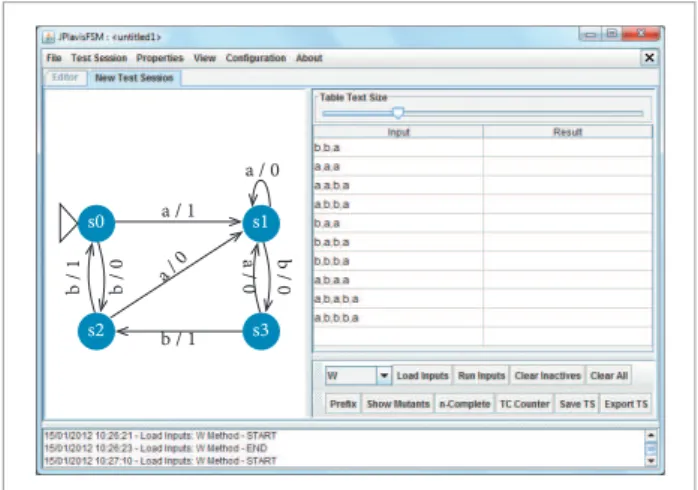
Other functionalities were implemented to assist test case handling, such as test set execution, inclusion/exclusion and enabling/disabling. Test sessions can be created, as shown in Fig. 2. In this window, the user can visualize the FSM on the let and the generated test cases on the right side (each line has
one test case). At the bottom, there is an option that helps the tester to create particular test sets by himself.
One of the best features of the JPlavisFSM’s test session is to support the construction of a test case set with a high probability of inding defects in the System Under Test (SUT). In a test session, the tester can import (or load) a set of test cases, which was automatically generated through one of the testing methods given by JPlavisFSM or manually generated by the tester. Once imported, the set of test cases can be executed (i.e., applied against the speciication) and the mutation score obtained.
he JPlavisFSM releases the following testing methods to generate test cases set: W, UIO, HSI and SPY. he W method generates test cases as follows. First, an initialized transition cover and a characterization set of the specification are determined. Secondly, for each sequence of the transition cover, each sequence of characterization set is appended. he UIO generates test cases as follows. First, an initialized transition cover is determined, as well as UIOs for each state. Secondly, for each sequence of the transition cover, the UIO of the state reached by that sequence is appended. HSI method generalizes the W method, and can be applied to partial FSMs. It irst determines a transition cover and a set of harmonized state identiiers. hen, for each sequence of the transition cover, each of the sequence in the identiier for the state reached by that sequence is appended. he SPY method generalizes the HSI method; the main diference is that both the transition cover and the harmonized state identiiers are computed “on-the-ly”, i.e., during the execution of the method, trying to minimize the number of test cases which are required to obtain complete test cases. For the HSI and SPY methods two versions are provided: the original
a / 1
b / 1 b / 1 b / 0
b / 0
a / 0
s0 s1
s2 s3
a / 0
a / 0
one and the auto-completed; the latter auto-completes the FSM before applying the original method. New methods can be incorporated in JPlavisFSM as plugins or be imported at runtime (provided that the compatible input/output formats are used) as well as providing more lexibility to the tool and the possibility to explore all the other features for the test set analysis.
Two diferent ways of evaluating a test cases set are provided: • Mutation Analysis; and
• n-Completeness Analysis (Simão and Petrenko, 2010).
he Mutation Analysis, provided by JPlavisFSM, allows a test set to be evaluated and also to be enhanced. his enhancement can be achieved by expanding the test set with test cases targeted at undetected mutations. he mutant operators (Fabbri et al., 1994) were designed according to the classes of faults detected on the FSM-based test models. When the user creates a test session, the mutants are automatically created and the user can access all the mutants to verify their statuses: alive, when the ongoing test fails to reveal the defect of the mutant; or dead, the other way around. his feature could help the user to upgrade test sets since this criterion guides the user to create tests that will run paths, which may contain defects. he n-Completeness analysis provides another way to verify the quality of a given test set, checking whether the test set is complete or not.
COFI METHODOLOGY
The CoFI methodology (Ambrosio, 2005) guides the functional testing activity. It was proposed considering the needs of space application’s validation and therefore deines steps for creating test cases for sotware embedded on-board of satellites in a systematic way in order to get as much reusability in testing as possible. he main objective is to help the tester to deine FSM-based models which represent the behavior of the SUT.
he SUT behavior’s decomposition into FSMs starts with the identiication of services, which can be a system function from the user’s viewpoint. Each service shall be described by a set of FSMs that map diferent classes of behavior. his classiication takes into account diferent kinds of input events:
• Normal (absence of faults); • Exceptions (foreseen faults);
• Unexpected inputs (inputs occurring when they are not expected); and
• Hardware faults.
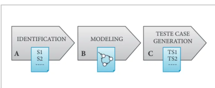
In short, the CoFI methodology consists of three steps: identiication, modeling and test case generation. Figure 3 shows the three steps of CoFI methodology described hereater.
(A) Identiication
Based on a given specification, the tester has to understand properly the external behavior of the SUT, as in the black-box testing. The information to accomplish this step can be extracted from textual specification documents, requirements, use-cases, sequence-diagrams, and also from interviewing experts in the SUT if necessary. In this step, it shall be identified:
• Services that an user can recognize or execute in the SUT; • Events and actions: it is necessary to identify all the
possible events and actions (or outputs) that can be, respectively, commanded and trigged (or observed). he selected events and actions will be abstracted as inputs and outputs in the FSMs;
• Control and observation points: they are addresses or mechanisms to input data and to obtain responses from the SUT;
• Physical faults: faults occurring in hardware. hey are to be considered whenever the SUT includes embedded sotware in a hardware and this sotware must have mechanisms to treat the faults;
• Facilities and constraints: the tools and theirs commands that supports the test execution against the SUT and the events that cannot be activated during the test execution.
(B) Modeling
In this step, for each service, the tester should develop four classes of behavior:
• Normal;
• Speciied exceptions; • Sneak path; and • Fault tolerance.
IDENTIFICATION
S1 S2
----TS1 TS2
----MODELING GENERATIONTESTE CASE
A B C
At least one FSM model shall be created representing the partial system behavior.
he normal behavior model deines the sequence of events that the SUT normally expects when it is executed. he tester has to identify the normal mode the SUT will be subordinated to and the events and actions expected for this case. For the
specified exceptions model the tester has to recognize the exceptions mentioned in the documents, as timeouts and unknown commands and thus deine the events expected in this context, called exception events. he sneak path model deals with the correct inputs arriving in wrong time. he objective is to predict the unexpected behaviors, i.e., to describe what the machine should do if an input occurs in a state where it is not deined. he tester can use the normal model as a basis, write it in tabular form (event × state) and ill the blank cells with the corresponding expected behavior. In some cases, there is no possible behavior to model, and then the tester evaluates the best option for the SUT. he transitions trigged by the unexpected inputs should be designed based on the normal model. Finally, the fault tolerance model shall map the possible physical faults when the SUT implements mechanisms to tolerate hardware faults. For each physical fault, the tester has to adapt the normal model including the fault events. At the end of the modeling step, the tester has a set of models representing the SUT’s behavior, from which test cases may be automatically generated.
(C) Test Case Generation
his step can be supported by testing tools that automatically generate a set of test cases (also named test sequences). In the experiences about applying CoFI described in Ambrosio et al. (2007), Pontes et al. (2009), Anjos et al. (2011) and Mattiello-Francisco et al. (2013), the Condado tool was used to automate the test cases generation. In our work, the JPlavisFSM tool was used because it provides ive diferent testing methods, including some variations that can be applied in partial FSM. Moreover, it has facilities to analyze the models’ properties and the adequacy of test case sets.
CASE STUDY: ITASAT’S
COMMUNICATION MODULE
We now discuss the case study we have carried out applying CoFI methodology and JPlavisFSM tool in a MBT approach
for a real system. he SUT is the Communication Module’s sotware of the ITASAT-1 satellite. he ITASAT Mission (Sato
et al., 2011) is part of a program funded by the Brazilian Space Agency (AEB) in the context of Action 4934 for Development and Launching of Small Technological Satellites developed by the Instituto Tecnológico de Aeronáutica (ITA) and other Brazilian universities. ITA is the responsible member for the project implementation and the Instituto Nacional de Pesquisa Espacial (INPE) provides technical consulting and laboratory infrastructure. he ITASAT-1 is a university satellite planned to execute experimental payloads namely, Digital Data Collection Transceiver, Heat Pipe Experiment, Micro Electrical Mechanical System for attitude determination and an Inter Satellite Link.
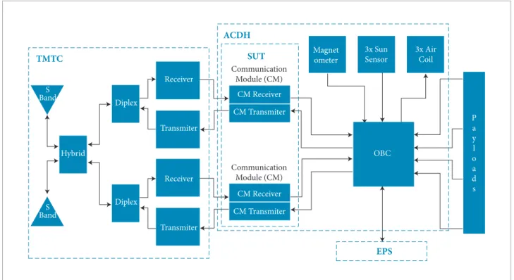
The satellite architecture is composed of five service subsystems: Mechanical Structure (MSS), hermal Control (TCS), Electric Power (EPS), Attitude Control and Data Handling (ACDH) and Telemetry & Telecommand (TMTC); the last three subsystems are shown in Fig. 4. he functions of the ACDH are commanded by the on-board computer (OBC). The Communication Module (CM), located in the ACDH subsystem, is in charge of the communication between the OBC and the TMTC. Figure 4 highlights the Communication Module and indicates that it is the System under Test (SUT), the focus of this study.
The CM comprises not only two receivers and two transmitters in redundancy, but also the sotware in charge of receiving commands arriving from the ground stations and transmitting telemetry collected from satellite pieces of equipment to ground stations.
he CM Sotware performs critical functions so it has to work properly for the space mission success. Its functions are to receive the telecommands from ground stations and to transmit the telemetries collected by the satellite’s payloads and sensors, to manage the payloads status and to turn of the pieces of equipment when a critical failure occurs leading the satellite into survival mode.
Considering that the CM is one of the most critical parts of this satellite, it was chosen as case study to experimentally evaluate the proposed approach. he three main steps that guided this study are illustrated in Fig.5.
(A) Identiication
in order to understand the context and the behavior of the CM’s sotware. he studies lasted 12 days, ive to understand the ITASAT-1 satellite documentation; ive to the CoFI guidelines and two to identify the main elements required by CoFI, namely, services, events, actions, faults, and so on.
We identiied two services corresponding to the two main functions of the Communication Module: (S1) receive commands from ground and (S2) transmit the collected telemetries from on-board equipment. hese functions are implemented respectively by the CM Receiver Sotware and by the CM Transmitter Sotware.
he events and actions extracted from the requirements are those naming the transitions of the FSMs illustrated in Figs. 6 and 7. he events and actions are abstract representations, i.e., they
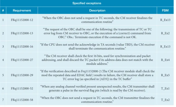
do not indicate a physical signal arriving. One example of a CM Receiver’s event is CmdOBCOK, that indicates the presence of one command to be executed. One action is StoreTC1wait, which indicates that the just-arrived telecommand shall be stored on board. Other examples are EndTimerB as event and StartTimerB as action to be performed by the CM Transmitter. For the CM Receiver Sotware, 12 events and 13 outputs were identiied, while for the CM Transmitter Sotware, 19 events and 12 outputs were identiied. Speciied exceptions were identiied in seven requirements, which are listed in Table 1. Concerning the physical faults, although they can occur, the Communication Module Sotware is not in charge of dealing with them, therefore, for testing purposes, the fault tolerance models were not created.
(B) Modeling
It was observed that on adopting the CoFI methodology’s guidelines the state explosion problem was avoided. First, we modelled the normal behavior of each service in the CM Receiver FSM (R_N) and the CM Transmitter FSM (T_N), as shown in Figs. 6 and 7, respectively.
For the FSM models used here, namely the Mealy machine (Mealy, 1955), all the transitions should be represented by a pair of input-output, which means that each event should be
ACDH
TMTC
S Band
S Band
Hybrid
Diplex
Diplex
Transmiter
CM Transmiter Receiver
CM Receiver
CM Transmiter CM Receiver
Communication Module (CM) Communication
Module (CM)
Magnet ometer
3x Sun Sensor
3x Air Coil
OBC
P a y l o a d s
Transmiter Receiver
SUT
EPS
Figure 4. ITASAT-1 satellite architecture.
IDENTIFICATION
CM Receiver and CM Transmitter
FSMs • Receiver
• Transmitter TS1TS2
JPlavisFSM
MODELING GENERATIONTESTE CASE
CoFI Methodology
associated with an action. Since in this sotware test some events were not associated with an observed output (or action), the output “Terminate” was used in the model to indicate the end of a transition. Another modeling condiction was made up to represent one transition requiring the occurrence of two events or transitions with two outputs. Figure 6 illustrates the
ACKandStartTimerC output, which, in practice, indicates two actions: “send an Acknoledgemessage” and “start the Timer C”. Regarding the specified exceptions, the FSMs R_Ex13, R_Ex2, R_Ex4 and R_Ex5 map the exceptions of the CM Receiver, and T_Ex1 and T_Ex2 map those of the CM Transmitter. Table 1 matches the FSMs to the ITASAT-1’s requirements they model. For sake of space, not all FSMs are shown in this paper. For more details see Pinheiro and Ambrosio (2013).
The CM Software has to handle timers which trigger timeout events needed for the communication timing. On the first analysis, to handle timers seemed an issue, because classical FSM does not treat time events. Therefore, these events were abstracted away in the model. The CoFI
guides the definition of timers as external devices that are started by an action and produce an event to the FSM when the time is expired, indicating a timeout. For the normal
behavior, the software only signalizes the start of a timer, as represented by StartTimerC and StartTimerA events. For the specified exception models, it was needed to represent events to indicate expired time, so we used the EndTimerC
and EndTimerA events.
The first CM Receiver’s FSMs were pointed out as non-deterministic by the JPlavisFSM, because the event
INT2TC associated to StoreTC action occurred in several states. On further analysis of the real software’s behavior we defined two abstractions to solve this problem: • A inite bufer to store at most three TCs, called TC1, TC2
and TC3; and
• Two actions to diferentiate TC stored and TC sent.
hen, to create several actions (outputs): StoreTC1wait, StoreTC1send, StoredTC2wait, and so on, instead of using only the StoreTC action.
Table 1. ITASAT-1 Requirements vs. Speciied Exceptions Models.
Speciied exceptions
# Requirement Description FSM
1 FRq11152000-12 “When the OBC does not send a request in TC seconds, the CM receiver finalizes the
communication routine” R_Ex13
2 FRq11152000-13
“he request of the OBC shall be one of the following: the transmission of TC or TC error log from CM receiver to OBC, or the execution of a (correct) command from
OBC.” Obs.: Terminate execution if the command is not OK.
R_Ex2
3 FRq11152000-16 “If the CPU does not send the acknowledge in TA seconds (value TBD), the CM receiver
shall terminate the communication routine.” R_Ex13
4 FRq11152000-27
“he CM receiver shall check the first 16 bits, used for synchronization and packet addressing, and shall discard the TC packet if its address data does not match with the
module address.”
R_Ex4
5 FRq11152000-29
“If the verification described in Frq11152000-2 (he CM receiver module shall check the mod the repeated data and EDAC field ) results in failure, the CM receiver shall store a
TC error log (as specified in [AD3]) in the TC bufer”
R_Ex5
6 FRq11152000-52 “When any analog channel verified present unexpected results, the CM transmitter shall
generate a pulse in the survival flag pin (which is read by the CM receiver). T_Ex1
7 FRq11152000-58 “When the OBC does not send a request in TC seconds, the CM transmitter finalizes the
EndTimerVand AnChVerOK / StartTimerV
EndTimerB / Empty q0 q1 q2 q3 q5 q4
EndTimerBandDB / StartTimerB
PackSurvTM / SendToTrans
O B C O NR es qN otF ro
mCPU / E
m p ty O B C O
FF / E
m p ty B ea co nO N an dT M n otC on
fig / C
on figT MT CT ra n sm B ea co nO
FF / e
m p ty B ea co nO N an dT M C on
fig / C
on
fig / A
nC hD tC oll ec t
EndTimerB / Empty
BeaconOnan
dTMConfig / Empty
Beacon Off / E
mpty
Beacon
ONeTM
notCo nfig / C
onfigTM TCTra
nsm
OBCOFF / Empty OBCONReqNotFromCPU / E
mpty
OBCONReq uestFromCP
U / ACK TM / Se ndT MandA CK CmdO BC / Se ndD tToCPU Cm dCo nfigFrom OBC / TranscC
onfig OBC ON Requ estF rom CPU
/ AC K EndT im erB / A nC hD ico llect
Figure 7. T_N: Finite State Machine representing the normal behavior of the CM Transmitter. INT1SurvFlag / OffdeviceseBeaconON
INT2 DirectTC / Execute
INT1SurvFlag / OffdeviceseBeaconON INT2 DirectTC / Execute
INT1SurvFlag / OffdeviceseBeaconON INT2 DirectTC / Execute
Cm
dO
B
C
O
K / A
CK
St
or
e / N
oT Cm sg Cm dO B C O
K / A
CK
Cm dO
BC OK
/ Te rm inat e Cm dO BC OK
/ Te rm inat e Cm dO BC OK
/ Te rm
inat e
Store dTC
/ TC 1a nd Sta rtT im erA Store dTC / TC
2a nd Sta rtT im erA Sto re dT C / T C 3and Sta rtT im erA Cm dO B C O
K / A
CK Cm dO B C O
K / A
CK
N
CPS
pin / A
CK a n dS ta rtT im erC N CPS
pin / A
CK a n dS ta rtT im erC N CPS
pin / A
CK a n dS ta rtT im erC N CPS
pin / A
CK a n dS ta rtT im erC
INT1SurvFlag / OffdeviceseBeaconON INT2 DirectTC / Execute
INT1SurvFlag / OffdeviceseBeaconON INT2 DirectTC / Execute
INT1SurvFlag / OffdeviceseBeaconON INT2 DirectTC / Execute INT1SurvFlag / OffdeviceseBeaconON
INT2 DirectTC / Execute INT2TC / StoreTC1wait
Wait0 ACK1 Send0 Buffer Send1 Buffer Send2 Buffer Send3 Buffer ACK2 ACK3
Wait1 INT2TC / StoreTC2wait Wait2 Wait3
INT2TC / StoreTC2entre
INT2TC / StoreTC1send INT2TC / StoreTC2send INT2TC / StoreTC3send
INT2TC / StoreTC3wait
INT2TC / StoreTC3entre INT1SurvFlag / OffdeviceseBeaconON
INT2 DirectTC / Execute
INT1SurvFlag / OffdeviceseBeaconON INT2 DirectTC / Execute
INT1SurvFlag / OffdeviceseBeaconON INT2TC / StoreTCFullwait
INT2 DirectTC / Execute
INT1SurvFlag / OffdeviceseBeaconON INT2TC / StoreTCFullwait
INT2 DirectTC / Execute
After concluding the normal behavior modeling, we analysed all events presented in the normal model, in order to create the sneak path models. However, because of the logic implemented in the hardware design construction, events never occur in an inappropriate state, so sneak path models were not designed. The fault tolerant models were not designed as well, because the CM is not in charge of dealing with the hardware faults. In the end of the modeling step, we had eight FSMs, as shown in Table 2.
The JPlavisFSM indicated incompleteness for all FSMs, consequently the traditional W method could not be applied. The completeness is a difficult property to be achieved when modelling the behavior of real systems, that is why the JPlavisFSM tool provides other methods, as HSI and SPY that do not require this propriety.
Summarizing, the modeling steps accounted for 16 days, being 8 days to create the normal and specified exception models including reviews and re-work in order to adequate the models to precisely represent the software behavior; and generate the test cases through the methods. Three adequacies were considered:
• Adequacy to the system – Do models represent the system?
• Adequacy to the FSM concepts and generation
methods – How can one abstract the model to achieve the FSM needs?
• Adequacy to the final model – Have the final models achieved the system objectives and the methods needs?
(C) Test Case Generation
We applied all methods for the eight FSMs. The W method’s applicability is restricted to complete, deterministic and initially connected FSMs. As the FSMs were not complete we used the JPlavisFSM’s function to auto-complete it before using the W method. The auto-complete functionality adds
all the missing transitions in a given state as self-loops, i.e., transition that starts and ends in the same state. Althought the auto-complete option leads to the generation of many test cases, which are not significant in practice, it allows the applicability of the W. One test case generated by W starting from the CM Receiver FSM normal behavior (Fig. 6) is given by the following sequence of inputs INT2TC, StoredTC, NCPSpin, and its corresponding expected output is StoreTC1wait,TC1andStartTimerA,ACKandStartTimerC. The UIO method requires a strongly connected FSM, whereas the SPY and the HSI can be applied into a
non-completed FSM. Thus, these methods have a wider applicability in comparison to the others; moreover, the test set generated by them is smaller than those genereted by W and UIO methods. On the other hand, it is possible to apply the UIO Method because it requires a separation sequence
defined for each state. One example of a test case generated by UIO method starting from the CM Transmitter FSM is BeaconONandTMnotConfig, OBCONRequestFromCPU, CmdOBC, EndTimerVAndAnChVerOK.
he HSI and SPY are based on separating sequences by pair of states (see Background section). hus, each pair of states must have a transition with an event in common with distinct outputs. In the FSMs of the CM Transmitter sotware no event occurs in more than one distinct state, so these methods were applied neither to T_N nor to T_EX1 and T_EX2. One test case generated by the SPY method is INT2TC, NCPSpin, StoredTC, INT2DirectTC, INT2TC, INT2DirectTC, INT2TC
which starts with the same input as the example to W method, but explores a valid sequence of events.
In general, all methods of the JPlavisFSM were applied to the created models. Table 3 shows the test sets generated by all methods for each FSM. The ‘-’ symbol indicates the method could not be applied and ‘*’ symbol indicates the use of auto-complete functionality.
Particularlly, the original W method did not generate any test case for the non-complete FSM, so there is no column for it. The original W was executed only thanks to the auto-complete feature. This option increases the number of transitions, leading to a large number of test cases.
The UIO method generated smaller sets, but the method does not guarantee the generation of complete sets. The HSI and SPY were successfully applied to CM Receiver FSMs because there was a separating sequence that distinguished their states. For CM Transmitter FSMs, it was not possible Table 2. Summary of models design.
FSM models by classes of behavior
Services Normal
Behavior
Exception Speciied
Sneak Path
Fault Tolerance
CM
Receiver 1 4 0 0
CM
to use the HSI and SPY methods, therefore using the auto-complete feature they could be applied. he auto-auto-complete feature was executed in CM Receiver FSMs only to show the increase in the number of test cases, caused by the extra transitions artiicially included in the FSM to enable the application of the methods.
We have also explored the JPlavisFSM’s functionality to calculate the minimal test set composed by test cases produced by all the methods. Ater creating a test set comprising all test cases, all the preixed test-cases are discarded and the minimal test set is generated by the tool. he test sets shown in the HSI* and SPY* columns were not considered, since the original methods, HIS and SPY, could be applied.
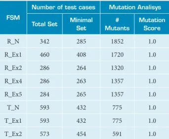
Table 4 illustrates the number of test cases derived from each model (considering the total set and the minimal set), the number of mutants created to each model and the mutation score obtained with both sets of test case. he mutation scores for the minimal and the total sets were the same, since only preixes are removed from the total set. he number of test cases (total and minimal sets) includes the tests generated by W*, UIO, HIS and SPY, but it does not include HIS* and SPY* to FSMs from CM Receiver.
All the methods (except UIO) generate complete test sets, but it is a theoretical concept which assumes that the implementation can be represented by an FSM with the same number of states of the speciication.
In general, to apply FSM-based testing implies handling a very huge number of test cases, so the tester must either be prepared to automate the test execution or select and prioritize the test cases. In our approach, we suggest a test strategy that could be adopted: first is to select the smallest test set generated by original methods; then, if there is still enough time to the testing activity, other sets could be applyed to improve the system’s reliability. In this case study, the SPY and UIO methods should be selected for CM Receiver FSMs and CM Transmitter FSMs, because the Mutation Score of these sets were 1.0 for each one, and they are complete sets as well.
he inputs and outputs represented in the models are abstracted to enable the creation of FSMs, this fact led to the generation of abstract test suites, so a post-processing of the test sets will be necessary before the test execution. his allows the test cases to be designed before deining some details of implementation and before the implementation is ready. Moreover, in the FSMs of the Comunication Module some
events shall be replaced by a set of others, as the case of the
INT2DirectTC, which corresponds to 23 diferent telecommands.
DISCUSSIONS AND RELATED WORKS
Various methods have been published to optimize the number of test cases to minimize the efforts required to obtain an acceptable level of software quality (Lai, 2002). However, these methods and test tools are yet rarely used in the software industry. Issues, such as ‘What are the hindrances
Table 4. Results of the generated Test Sets.
FSM
Number of test cases Mutation Analisys
Total Set Minimal
Set
# Mutants
Mutation Score
R_N 342 285 1852 1.0
R_Ex1 460 408 1720 1.0
R_Ex2 286 264 1320 1.0
R_Ex4 286 263 1357 1.0
R_Ex5 284 265 1357 1.0
T_N 593 432 775 1.0
T_Ex1 593 432 775 1.0
T_Ex2 573 454 591 1.0
Table 3. Number of tests generated by method for each Finite State Machine.
FSM W* UIO HSI HSI* SPY SPY*
R_N 234 48 38 78 22 40
R_Ex13 356 44 34 89 26 42
R_Ex2 201 37 27 67 21 40
R_Ex4 201 37 27 67 21 40
R_Ex5 201 37 27 67 19 37
T_N 316 21 - 184 - 72
T_Ex1 316 21 - 184 - 72
to the adoption of the generation methods based on FSM in the industry?’ or ‘What is the gap between academic and industrial testing methods?’ have been investigated in order to ease the diiculties of employing FSMs in the real context. In this section we discuss these questions in general speaking and concerning our approach.
The fault domain, introduced in Background section, is deined for general purpose FSM. hat fault domain provides all possible faults that can happen in the model. However, it may be interesting to adapt the model to the real scenario that should be tested. In Srivastava and Singh (2009) a fault model based on FSM to embedded systems was proposed. he fault model provides three kinds of errors that could occur among the connections between the hardware and sotware components: unconnected outputs, when the implementation should activate an output but does not activate, in other words, there is no output ater a transition happens; unconnected inputs, when an input event has no behavior efect, there is no transition to another state as expected; and redirected inputs, which occur when an input is redirected to an incorrect state and generates a wrong behavior. he requirements for the construction of the test set were deined according to the new fault domain. he main focus of Srivastava and Singh is on the deinition of the domain applied to embedded systems; and a testing generation method is not applied.
In Santiago et al. (2008) a test environment that supports the generation of test sequences based on Statecharts and FSMs is presented. he simplicity of the model is considered the main advantage of employing FSMs as a technique for modeling reactive systems. Methods such as W and UIO were applied in the context of embedded systems.
Although the applicability of MBT has been widely investigated, there are some reasons for reluctance in adopting academic methods for FSM-based testing. We have evaluated some of the reasons presented in Lai and Leung (1995) and Lai (2002), such as feasibility, that concerns the use of the testing methods in real cases; extreme formalism, that gives the impression of being too academic; need for training or education in this area; and resistance to changing, because it is not necessary the use of formal methods to do tests, according to the current point of view of many industries acting in the satellite-based sotware sector.
he diiculty in using MBT starts with the modeling phase. Identifying the system inputs and outputs, as well as the system behaviors, is not a trivial task. A broad knowledge about the system and about FSM is necessary to understand how a
non-formal speciication could be transformed into a formal one. In our approach, CoFI methodology helped to deal with these diiculties. he tester is guided, step by step, to model the system behavior into several simple FSMs. Moreover, the JPlavisFSM tool facilitated itting the models to the testing methods, automating the test cases generations, producing test sets’ metrics allowing the tester to choose the best testing set. he tester must yet interpret the generated test sets due to the abstraction of the model, though the practicality of MBT was improved by CoFI and JPlavisFSM. he formalism of the FSM-based testing methods is transparent to the JPlavisFSM tool user. he analysis of FSM properties is automatically generated. Some validations with the use of FSM-based testing techniques and CoFI methodology have been conducted (Anjos et al., 2011; Pontes et al., 2012; Mattiello-Francisco
et al., 2013). In such cases the Condado (or ConData) (Martins
et al., 1999) was used as a tool to automatically generate test cases. Condado tool does not have neither the facilities to FSM structural analysis nor diferent methods to be chosen, however the single FSM property it requires is the FSM be connected. In the approach presented here, the FSMs have more elaborated structures, so the facilities provided by the JPlavisFSM tool allowed improving the application of the CoFI. Besides that, it was applied to real embedded sotware of satellite application.
Concerning the training aspect, JPlavisFSM tool can be used to teach how the generation methods work. he tool has the option to import extra methods. he user may implement his/ her own method and apply the n-Complete tool to analyze if the method is correct. he JPlavisFSM may be used to support the modeling phase too, since the GUI is simple, clean and it provides functionalities for analyzing FSMs. he usability improvements provided by JPlavisFSM and the guidelines of CoFI methodology were tentative of reducing the gap between the good results obtained in academia with testing methods and its use in practical cases of industry as discussed in Lai and Leung (1995).
CONCLUSION
his paper has reported on the applicability of the FSM-based testing in the real, developed Communication Module sotware of the ITASAT university satellite. As testing is a costly activity, automating the generation of test cases can help reduce the costs. In this sense, MBT is an approach that derives test cases from a formal model built to support the testing activity. On the other hand, real systems like ITASAT sotware should be tested taking into account requirements of timing and reactions to events. In this context, the systematic approach of CoFI methodology supported by the formalism implemented by JPlavisFSM could be an alternative to test the system. We have observed restrictions and beneits on applying this approach. Some observed limitations, which should be issues for new investigations, are:
• he modeling phase is not trivial and some knowledge about FSM is required to start the process. he tester has to learn the basic concepts and structural properties of FSM; • he applicability of the generation methods is highly
dependent on structural properties of FSM generated in modeling phase. he tester has to know the basic theory about the generation methods;
• he abstraction of the system is required to build models, so the test set generated is an abstract set of inputs and outputs, which needs to be interpreted before being executed. So, the post-processing of test sets could aggregate an extra cost to the test execution phase.
he observed beneits were:
• he CoFI methodology guides the modeling phase, which helps the inexperienced testers start using the FSM technique;
• he FSM-based test generation was automated leading to cost reduction of the test activity;
• he JPlavisFSM tool eliminates the need of profound theoretical knowledge about FSM structural properties and testing generation methods.
he MBT still has some practical limitation, but the initiatives that were made in academia helps to reduce them. he deinition of new generation methods which do not require properties, such as FSM minimality, has to be explored. At the same time, the industry needs to step forward on the use of formal methods. hese initiatives will improve the eiciency and efectiveness of testing activity.
As future work, we envision the following. he generated test sets must be post-processed and executed against the Communication Module implementation of ITASAT and the complexity of these activities should be analyzed against the obtained results.
ACKNOWLEDGMENTS
he authors would like to thank professors Emília Villani, David Fernandez and Wilson Yamagutti for the opportunity of applying the proposed approach in the ITASAT project. he authors would also like to thank the inancial support of FAPESP, CNPq and CAPES. he authors are very thankful to reviewers for their useful comments.
REFERENCES
Alencar, W.A.F., 2013, “Model checking aplicado a software embarcado crítico do satélite universitário ITASAT”, Dissertação de mestrado, ITA, São José dos Campos, Brazil.
Anjos, J.S., Gripp, J., Pontes, R. and Villani, E., 2011, “Applying the CoFI testing methodology to a multifunctional robot end-effector”, São José dos Campos, SP, Brazil.
Ambrosio, A.M., Martins, E., Vijaykumar, N.L. and Carvalho, S.V., 2005, “Systematic generation of test and fault cases for space application validation”, In Proceedings of the 9th ESA Data System in Aerospace (DASIA), Edinburgh, Scotland. Noordwijk: ESA Publications.
Ambrosio, A.M., 2005, “CoFI: uma abordagem combinando teste de conformidade e injeção de falhas para validação de software em
Aplicações Espaciais”, Tese de doutorado, INPE-13264-TDI/1031. 206p.
Ambrosio, A.M., Mattiello-Francisco, F., Santiago, V.A., Silva, W.P. and Martins, E., 2007, “Designing fault injection experiments using state-based model to test a space software”, Third Latin-American Symposium on Dependable Computing (LADC), Morelia, México. Lecture Notes in Computer Science (LNCS) series. Springer Editors: Bondavali, A.; Brasileiro, F.; Rajsbaum, S. Springer, Berlin. pp. 170-178. doi: 10.1007/978-3-540-75294-3_13.
Delamaro, M.E., Maldonado, J.C. and Jino, M., 2007, “Introdução ao Teste de Software”, Elsevier.
Fabbri, S.C.P.F., Maldonado, J.C., Masiero, P.C. and Delamaro, M.E., 1994, “Mutation analysis testing for finite state machines”, In Fifth International Symposium on Software Reliability Engineering, Monterey, California, USA, pp. 220-229.
Fujiwara, S., Bochmann, G.Von, Khendek, F., Amalou, M. and Ghedamsi, A., 1991, “Test selection based on finite state models”, IEEE Transactions on Software Engineering, Vol. 17, No. 6, pp. 591-603. doi: 10.1109/32.87284.
Gill, A., 1962, “Introduction to the theory of finite-state machines”, McGraw-Hill, New York.
Hierons, R.M. and Ural, H., 2010, “Generating a checking sequence with a minimum number of reset transitions”, Automated Software Engineering, Vol. 17, No. 3, pp. 217-250. doi: 10.1007/s10515-009-0061-0.
Lai, R. and Leung, W., 1995, “Industrial and academic protocol testing: the gap and the means of convergence”, Computer Network ISDN System, Vol. 27, No. 4, pp. 537–547. doi: 10.1016/0169-7552(93)E0110-Z.
Lai, R., 2002, “A survey of communication protocol testing”, The
Journal of Systems and Software, No. 62, pp. 21-46.
Martins, E., Sabião, S.B. and Ambrosio, A.M., 1999, “ConData: a Tool for Automating Speciication-based Test Case Generation for Communication Systems”, Software Quality Journal, Vol. 8, No.4, pp. 303-319.
Mattiello-Francisco, M.F., Ambrosio, A.M., Villani, E., Martins, E., Dutra, T. and Coelho, B., 2013, “An experience of the technology transfer of CoFI methodology to automotive domain”, LADC, Industrial track. BDBComp Biblioteca Digital.
Mealy, G.H., 1955, “A Method for Synthesizing Sequential Circuits”. Bell System Technical Journal, Vol. 34, No. 5, pp. 1045-1079.
Moore, E.F., 1956, “Gedanken–experiments on sequential machines”, in Automata Studies. Princeton University Press, pp. 129-153.
Morais, M.H.E and Ambrosio, A.M., 2010, “A new model-based approach for analysis and reinement of requirement speciication to space operations”, In Proceedings of the 10th Conference on Space Operations. Huntsville, Alabama, USA. SpaceOps 2010. American Institute of Aeronautics and Astronautics (AIAA). doi: 10.2514/6.2010-2231.
Morais, M.H.E., 2011, “Uma abordagem para a melhoria da qualidade de requisitos baseada em modelos de estados”, Dissertação de mestrado. INPE, 2011. São José dos Campos.
Pedrosa, L. and Moura, A., 2010, “Generalized partial test case generation method”, In 4th International Conference on Secure Software Integration and Reliability Improvement Companion (SSIRI-C 2010). Washington, DC, USA: IEEE Computer Society, pp. 70-77.
Petrenko, A., Yevtushenko, N., Lebedev, A. and Das, A., 1993, “Nondeterministic state machines in protocol conformance testing”, in Proceedings of the 6th International Workshop on Protocol Test systems VI (IFIP TC6/WG6.1). Amsterdam, The Netherlands, The Netherlands: North-Holland Publishing Co., pp. 363-378.
Pinheiro, A.C. and Ambrosio, A.M., 2013, “Modelagem do Módulo de Comunicação do Satélite ITASAT – Segundo a metodologia CoFI”, Relatório de Pesquisa,
sid.inpe.br/mtc-m19/2013/10.04.19.58-NTE. INPE, São José dos Campos. Retrieved in March, 19th 2014, from http://urlib.net/8JMKD3MGP7W/3EUF338
Pinheiro, A.C., 2012, “Subsídios para a aplicação de métodos de geração de casos de testes baseados em máquinas de estados”, Dissertação de mestrado. ICMC. USP. São Carlos, Brazil.
Pontes, R.P., Morais, M.H.E., Véras, P.C., Ambrosio, A.M. and Villani, E., 2009, “A comparative analysis of two verification techniques for DEDS: Model checking versus model-based testing”, In 4th IFAC Workshop on Discrete Event System Design (DEDS), Valencia, Spain, pp. 70-75.
Pontes, P.R., Véras, P.C., Ambrosio, A.M. and Villani, E., 2012, “Contributions of model checking and CoFI methodology to the development of space embedded software”, Empirical Software Engineering – An International Journal, Vol. 10, No. 2, Springer. Online FirstTM, doi: 10.1007/s10664-012-9215-y - ISSN 1382-3256.
Romero, A.G., Ambrosio, A.M. and Souza, M.L.O, 2012, “Finite state-machine veriication applied to hybrid systems”, 21st SAE BRASIL International Congress and Exhibition, Expo-Center Norte, São Paulo, Brazil. doi:10.4271/2012-36-0429.
Sabnani, K. and Dahbura, A., 1988, “A protocol test generation procedure”, Computer Networks and ISDN Systems, Vol. 15, No. 4, pp. 285-297. doi: 10.1016/0169-7552(88)90064-5.
Santiago, V., Vijaykumar, N.L., Guimarães, D., Amaral, A.S. and Ferreira, E., 2008, “An environment for automated test case generation from statechart-based and finite state machine-based behavioral models”, In Proceedings of the 2008 IEEE International Conference on Software Testing Verification and Validation Workshop. Washington, DC, USA: IEEE Computer Society, pp. 63-72.
Sato, L.S., Saotome, O., Timm, C., Fernades, D. and Yamaguti, W., 2011, “Itasat-1: Brazilian university microsatellite for payload test and validation in low earth orbit”, In Proceeding of the 8th Symposium on Small satellites for Eath Observation, Berlin, Germany.
Simão, A.S., Ambrosio, A.M., Fabbri, S.C.P.F., Amaral, A.S.M.S., Martins, E. and Maldonado, J. C., 2005, “Plavis/fsm: an environment to integrate FSM-based testing tools”. In Simpósio Brasileiro de Engenharia de Software - Sessão de Ferramentas. Universidade Federal de Uberlândia. Uberlândia, Brazil.
Simão, A.S., Petrenko, A. and Yevtushenko, N., 2009, “Generating reduced tests for fsms with extra states,” In Proceedings of the 21st IFIP WG 6.1 International Conference on Testing of Software and Communication Systems and 9th International FATES Workshop, ser. TESTCOM ’09/ FATES ’09. Berlin, Heidelberg: Springer-Verlag, pp. 129-145.
Simão, A.S. and Petrenko, A., 2010, “Checking completeness of tests for finite state machines”, IEEE Transactions on Computers, Vol. 59, No 8, pp. 1023-1032. doi:10.1109/TC.2010.17.
Srivastava, S. and Singh, A., 2009, “Testing of embedded system using fault modeling”, pp. 177-180. doi:10.1109/ ELECTRO.2009.5441142.
Utting, M. and Legeard, B., 2007, “Practical model-based testing: A tools approach”, 1st ed. Morgan Kaufmann.
Yin, Y., Li, Z. and Liu, B., 2010, “Real-time embedded software test case generation based on time-extended EFSM: A case study”, In Proceedings of 2nd WASE International Conference on Information Engineering (ICIE’10), pp. 272-275.