*e-mail: [email protected]
1. Introduction
In an electric steelmaking, there are great concerns about the operational variables that limit production in the continuous casting process. This process consists of passing the steel ladle from tapping to teaming, until the formation of the semi-inished product. One of the major factors that can delay the process is called ‘non-free opening’ of the slide-gate system that block the low of steel from the teaming ladle to the tundish. Eventually, the low of steel can be re-established using an oxygen lance cutting process which, besides its intrinsic slowness, can cause damage to the refractory material and risks of operational safety.
In order to avoid the contact between molten steel and the slide-gate system, a granular refractory material is used, called ‘iller sand’. Different types of iller sands can be employed into the inner area of the nozzle and the well block. Chromite based sands are one of the most widely used materials. Several operational variables and materials characteristics affect their performance1.
Important and necessary properties of the iller sands have already stated: refractoriness, particle-size distribution, particle-packing density, low thermal expansion, lowability, and above all, the capacity to form a sintered crust with an appropriate thickness when brought in direct contact with the molten metal2.
The ideal iller sand must have a balance between refractoriness and surface melting, producing a sintered surface but avoiding a very thick sintered layer. The formation of a thicker sintered layer requires a greater pressure to be broken, which dificult the free opening. On the other hand, the rapid sintering of the surface of the iller sand, favors the
free opening, because it prevents the penetration of liquid steel into the inner area of the nozzle of the low system3, 4. In this way, temperature and contact time of the liquid steel with the iller sand play a decisive role in the performance of the system.
Farshidfar and Kakroudi5 studied the use of the chromite based sands in continuous casting process. Their best results were obtained with the appropriate particle size distribution that favors the lowability and the permeability factor of the iller sand. Particle size distribution has also a strong inluence to promote the nozzle iller sand lowing when the sliding gate is opened6. The presence of carbon decreases wetting of the sands by liquid steel and concomitantly its penetration on the sand bed7. The presence of graphite causes the freeze plane to move closer to the hot face, minimizing steel penetration7.
The present study aimed to improve the understanding of the operational variables and the materials properties of the iller sand in order to increase free opening eficiency. The free opening was evaluated considering particle size, lowability, chemical composition and microstructure after iring of different iller sands. Some parameters of the steel production process were considered in order to enrichment the study. Thus, free opening rate was evaluated as a function of contact time (molten steel/iller sand), process temperature and wt% C in the steel.
2. Material and Methods
Two commercial chromite iller sands (A1 and B1) from two different suppliers were selected for this work. Subsequently, based on the materials characterization,
Free Opening Performance of Steel Ladle as a Function of Filler Sand Properties
Ricardo Thomé da Cruza*, Gustavo Frassini Pelisserb, Wagner Viana Bielefeldtb, Saulo Roca Bragançaa
aLaboratório de Materiais Cerâmicos – LACER, Federal University of Rio Grande do Sul – UFRGS,
Av. Osvaldo Aranha, 99/705, CEP 900135-190, Porto Alegre, RS, Brazil
bLaboratório de Siderurgia – LASID, Federal University of Rio Grande do Sul – UFRGS,
Av. Bento Gonçalves, 9500/sector 6, CEP 91501-970, Porto Alegre, RS, Brazil
Received: June 17, 2015; Revised: November 16, 2015; Accepted: January 4, 2016
The secondary steel reining process uses iller sand as a thermal insulating barrier that separates the liquid metal from direct contact with slide-gate system of the steel ladle. The effective use of this practice must provide a high free opening rate, impacting on increased productivity and quality of steel, reducing the number of stops, thermal loss and even the steel re-oxidation. Both operational parameters and material properties have inluence on the free opening rate. In the present work, two chromite-silica sands were analyzed, and some composition changes were proposed. The properties of these materials and the relevant process parameters were evaluated according to the free opening rate under normal operational conditions. The increases in carbon content and in particle size were considered the main factors relating to the iller sand. The percentage of free opening is also strongly inluenced by time and temperature of the steel contact.
laboratory pre-tests and results from literature5-7, some modiications of the materials properties were proposed to both suppliers. Thus, two new chromite sands have been developed - A2: increase in carbon content and particle size; B2: increase in particle size. Therefore, the present study includes laboratory characterization and evaluation of the performance under operational conditions of four sands in the industry.
The iller sands were evaluated in a semi-integrated mini mill that produces long carbon steels especially for civil construction industry. The ladle has approximately 2.5m height and 21.5 ton of steel production capacity.
X-ray luorescence (Shimadzu spectrometer - 1800), X-ray diffraction (Philips X’Pert), particle size distribution (by sieve), lowability index (ratio between the mass poured and vibrated) were used to the characterization of the iller sands. The effect of sintering temperature on the materials was also analyzed: parts of iller sand (5 bodies) were prepared by uniaxial pressing, and ired at 1500°C in an electric furnace, so the porosity was measured (Archimedes test). This test and the microstructural analysis were related to materials particle size and carbon content.
Thermodynamic study was performed using FactSage 6.4 commercial software. A general description of the software and databases as well as its current modiications8 was provided by Bale et al.,9 Speciically, the temperature and amount of liquid phase formation was investigated. The data were confronted to practical results by iring the samples at 1600°C in graphite crucibles in an electric furnace with argon atmosphere (LINN High Therm furnace HT-2100-Vac-Graphit-Special). These samples were analyzed in the scanning electron microscopy-SEM (Hitachi, TM3000).
The percentage of carbon in the tested materials can be considered too small to have signiicant inluence on the formation of oxide phases (liquid and solid), from a thermodynamic point of view. The FactSage´s simulations have not considered carbon dissolution in the liquid the formation, nor in the reaction/formation of any complex oxide phase combined with carbon. CO2 was regarded as gas phase, and so total carbon was not considered in the simulations.
As is known, in industrial conditions some process parameters cannot be modiied. In the present study, the analysis of the results have not evaluated changes in the dimension and shape of the ladle nozzle, ladle capacity, amount of sand added, and others operational procedures typical of the mini mill were the data were obtained. The performance of the iller sand was evaluated considering approximated temperature and time of steel contact. In addition, the free opening rate also was evaluated as a function of time, temperature and wt% C in the steel. The data of 6 months of production was
considered. The free opening rate was calculated according to the ratio: nº of runs with free opening / nº of the total runs. At least, 100 runs were used for each parameter (time, temperature and wt% C) evaluated.
3. Results and Discussion
3.1. Characterization of the iller sands
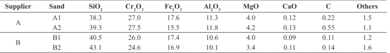
Table I shows the chemical composition of the four iller sands tested in this work. Considering A1 to A2 an increase in %C was realized. Others variations in chemical composition were a consequence of batch preparation by the suppliers. For example, it can be noted an increase in silica and a small decrease in chromium oxide content when B2 is compared to B1.
Therefore, besides the higher carbon content in sample A2, the main change (A1 to A2; B1 to B2) was in the particle size distribution. The percentages of medium size particles were increased and the percentages of ine particles were reduced (Table II).
Figure I shows the XRD analysis for one of the sands since the same pattern was observed for all samples. According to the obtained XRD results, the main phases are quartz (SiO2) and magnesiochromite ((Mg, Fe) (Cr,Al)2O4). This phase is a solid solution of FeCr2O4, a spinel compound usually referred as chromite5.
In function of the particle size distribution alteration, the lowability index (Table III) of A2 and B2 sands was improved, what means a higher lowability and a better illing capacity10.
A higher particle size also contributes to an increasing of the porosity of the sintered parts (pressed bodies). Table III also shows that the apparent porosity of the samples sintered at 1500°C increased slightly, comparing A1 to A2 and B1 to B2.
Table I. Filler sands chemical composition.
Supplier Sand SiO2 Cr2O3 Fe2O3 Al2O3 MgO CaO C Others
A A1 38.3 27.0 17.6 11.3 4.0 0.12 0.22 1.5
A2 39.3 27.5 15.5 11.8 4.2 0.13 0.55 1.1
B B1B2 40.5 26.0 17.4 10.6 4.0 0.09 0.11 1.2
43.1 24.6 16.9 10.1 3.4 0.11 0.14 1.6
Figure II shows the microstructures of the sands sintered at 1600°C. The EDS analysis was used to help phase identiication (tables inserted in the igures). It is observed that all aggregates (areas 1) are chromium oxide, the major refractory part of these materials. The aggregates are surrounded by a matrix of higher silica content (areas 2), which has a lower melting point, and has an aspect of a completely fused material. Areas 3 are a mixture of matrix and aggregates. As pointed out before (Table I), the EDS analysis also did not show big differences between the compositions of the four samples.
It can be observed that the microstructures of the sintered sands exhibit a good distribution of aggregates, which favors its behavior on duty. The cracks probably are originated due to difference in thermal expansion of the material phases,
creating tensions that can break the part during cooling. In addition, these cracks demonstrate the weakness of the part, what can facilitate the free opening. The pores showed in Figure II are rounded and isolated what contributes to a higher thermal insulation.
The correct amount of aggregate and matrix phases is the key to optimize the performance of the iller sands. Thus, the sintering degree of the sands depends on raw materials quality and preparation, speciically, particle size and carbon content. In addition, it depends on the process variables, such as ferrostatic pressure, temperature, and contact time.
The fraction of liquid in iller sand has two effects. First, it promotes the formation of a sintered surface layer which prevents the penetration of the molten steel into the nozzle. Thus, a rapid formation of the sintered layer favors free opening: the lower the penetration of the steel inside the nozzle, the lower will be the pressure needed to break up the sintered layer. Second, an excessive sintering, as stated before, can hinder the opening of the nozzle.
Figure III shows the liquid fraction of the sands in function of temperature. The difference is small at 1600°C: ~8% for A1 to A2, and 5% for B1 to B2 formulations. As mentioned before, small variations in chemical composition (Table I), typically of batch preparation, may have small inluence on sands behavior in operation. However, the results shown in Figure III pointed out that the liquid fraction can vary signiicantly with temperature change. This represents a variation of the sintering degree from top to bottom of the sands in the casting nozzle. From 1350 to 1500°C the variation of the liquid fraction is quite signiicant and very sensitive to temperature variation.
According to Figure III, A2 showed the highest liquid fraction at 1600°C, and higher percentage of liquid phase at lower temperatures. The liquid phase formation at lower temperatures is essential to promote fast sintering on the sand layer surface. This sintered surface layer is important to
Table II. Particle size analysis of the iller sand (A1, A2, B1 and B2).
Sieve mesh (dpi mm)
Weight % retained
A 1 A2 B1 B2
-14+16# (1.3) 1.5 1 4.5 5.3
-16+20# (1.125) 1.1 1.3 2.6 3.4
-20+35# (0.67) 12 23.6 8.7 11.0
-35+60# (0.375) 46.3 51.4 39.2 54.3
-60+100# (0.199) 38.8 22.1 44.8 24.9
Mean diameter (mm) 0.29 0.35 0.29 0.34
Table III. Flowability index (raw materials) and apparent porosity (after iring) of the iller sands.
Sand Flowability index Apparent porosity
A1 1.14 9.8 ± 0.1
A2 1.11 12.1 ± 0.3
B1 1.21 12.1 ± 0.2
B2 1.15 13.2 ± 0.3
avoid the iniltration and solidiication of liquid steel between sand particles and also, avoid the pull out of nozzle iller particles by liquid steel6. Nonetheless, the data in Table III had shown higher porosity for A2, what can be explained by a predominant factor: higher particle size (and lower surface area). A2 also have higher percentage of carbon. The presence of carbon may act as a sintering inhibitor, because it covers the particles with a thin layer, inhibiting direct contact between them6.
It can be summarized that according to Figure III liquid fraction has a strong dependence with temperature variation. Figure II showed that mechanical strength depends on the degree of sintering of the parts (eg. crack formation and pore size). Table III also revealed an increase in the porosity from A1 to A2 and B1 to B2. Chemical composition (Table I) have not shown signiicant variation and is a dificult parameter to be controlled at small levels. Therefore, particle size and carbon content are easier parameters to be manipulated and prove to be effective to control iller sand sintering behavior.
3.2. Sands A1, A2, B1 and B2 in industrial tests
The rate of free opening eficiency is shown in Table IV. The increase in free opening percentage was favored by the increase of particle size (Table II), disregarding the small differences in chemical composition. Among all the sands analyzed, A2 presented the best result. This can be attributed to the higher particle size, porosity after iring, lowability (Table III), and the higher carbon content.
Therefore, the breaking of the sintered layer in A2 was easier, resulting in a higher free opening. In this context, the highest free opening presented by A2 can be related to the speciic material properties, according to the changes proposed, making this material more eficient compared to A1.
3.3. Free opening rate as a function of process
time and temperature.
Temperature has a strong inluence on the free opening, as previously mentioned. In Figure IV, it is observed that the curves of steel %C and process temperature presented the same behavior in relation to free opening rate. Therefore, process temperature determines the percentage of free opening, since it has direct inluence on the sintering degree of the sands. As already known, steels with higher percentage of carbon have lower teeming temperatures. Catchcart 11 and
Balagee12 have shown in their works that steels with higher percentage of carbon had a higher free opening rate.
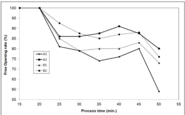
Figure V shows the tendency to decrease the free opening rate due to the increase of steel contact time. A longer steel treatment time means an increase on the thickness of the sintered layer. Therefore, the ferrostatic pressure required to open the steel low becomes greater with time increasing. As expected, A2 showed a higher free opening rate comparing to the other sands. After 30 min the free opening rate decreased approximately 15%. The effect of the steel processing time was also showed in the study of Catchcart11.
4. Conclusions
The results of this work show that the free opening rate depends on the operational parameters tested in this work, such as contact time between molten steel and iller sand, process temperature and wt% C in the steel, and physical and chemical properties of the iller sand. They control the sintering of the iller sand in the inner nozzle, which determines the free opening. Since not all operational
Table IV. Free opening rate (%) according to the type of sand. Time, temperature and steel quality were ixed.
Sample A1 A2 B1 B2
(%) 77.3 89.8 82.8 84.8
Figure V: Free opening rate as a function of the steel treatment time. A1, A2, B1 and B2 iller sands.
Figure III. FactSage simulation. Liquid fraction as a function of
parameters are susceptible to practical changes, the best type of sand to each steelmaking (and to each type of steel) should be optimized carefully.
A2 was the best iller sand for the steelmaking studied. It was formulated with higher percentage of carbon and higher particle size than the formulation in use. The carbon inhibits direct contact of the particles, and diminishes the wetting by molten metal, favoring the formation of weaker sintered materials. The particle size affects directly the sintering degree of the material. For both studied materials (A1 and B1) an increase in the particle size (A2 and B2) enhanced the apparent porosity after iring, what resulted in a higher free opening. The increased on porosity suggests
the formation of a weaker sintered layer due to the increase of critical law size.
Particle size and carbon content are easier parameters to be handled and the results presented in this works proved that they have a strong inluence in iller sand sintering behavior and, consequently, ladle free opening.
The temperature and treatment time of steel have strong inluence on the sintering of iller sand. An increase in these parameters can decrease free opening. Considering longer steel treatment, A2 showed the best results. It keeps on an average of 80% of free opening rate even for 50 min of treatment in the ladle.
References
1. Tomba AG, Camerucci MA, Cavalieri AL. Ladle Filler Sand Evaluation [C] // Holger Evele, William D Faust. In: Proceedings
of the Uniied International Technical Conference on Refractories (UNITECR 05). Orlando: Curran Associates Publishers. 2005;
16p.
2. Tseng T-T, Wu H-M, Chen C-N, Cheng C-C, Uan J-Y, Wu W, et al. Refractory filler sands with core–shell composite
structure for the taphole nozzle in slide-gate system of steel ladles.
Ceramics International. 2012;38(2):967–971. doi:10.1016/j.
ceramint.2011.08.017
3. Pan H, Ko Y. Constituents and characterization of packing sand
for sliding gate systems for steel ladles. American Ceramics Society. 1981;60:736–739.
4. Chien YT, Pan HC, KO YC. Preparation and performance
of packing sands for sliding-gate systems for steel ladles.
Ironmaking Steelmaking. 1982;9:252–257 .
5. Farshidfar F, Kakroudi MG. Effect of chromite-silica sands
characteristics on performance of ladle filler sands for continuous casting. Journal of Iron and Steel Research. 2012;19(3):11-13.
6. Seixas ML. Moisture influence on performance of nozzle
filler for continuous casting of steel. In: XXXIX Steelmaking Seminar - International, 2008 May 12-16. Curitiba- PR.
7. Landy RA. Magnesia refractories. In: Schatcht CA, editor. Refractories Handbook. New York: Marcel Dekker; 2004. 8. Bale CW, Chartrand P, Degterov SA, Eriksson G, Hack K,
Mahfoud RB, et al. FactSage thermochemical software and
databases. Calphad. 2002;26(2):189-228. doi:10.1016/S0364-5916(02)00035-4
9. Bale CW, Bélisle E, Chartrand P, Degterov SA, Eriksson G, Hack K, et al. FactSage thermochemical software and
databases. Recent developments. Calphad.
2009;33(2):295-311. doi:10.1016/j.calphad.2008.09.009
10. Reed JS. Principles of ceramic processing. 2nd ed. New York: John Wiley & sons; 1995.
11. Cathcart CR, Hole PJ, Minion RL. Ladle Free Open and Choke Free Improvement at Stelco Hilton Works. In: Steelmaking Conference Proceedings, 2000. http://digital.library.aist.org/
pages/PR-060-361.htm
12. Balagee SR, Bradley JE. Ladle free-opening performance