Materials Research, Vol. 11, No. 4, 405-408, 2008 © 2008
*e-mail: [email protected]
Characterization of Manganese Alloy Residues for the Recycling of
FeSiMn and High-Carbon FeMn fines
Geraldo Lúcio de Fariaa*, Érica Linhares Reisa, Fernando Gabriel da Silva Araújoa,
Cláudio Batista Vieiraa, Fernando Leopoldo von Krügerb, Nelson Jannotti Jr.c
a
Programa de Pós-Graduação em Engenharia de Materiais/REDEMAT/UFOP
Praça Tiradentes 20, Centro, Ouro Preto - MG, Brazil
b
Fundação Gorceix
Logradouro 390, Gleba B, Vila Itacolomi, Ouro Preto - MG, Brazil
c
Manganese and Alloys Department, Companhia VALE
Rancharia, s/n, zona rural, Ouro Preto - MG, Brazil
Received: December 6, 2007; Revised: November 12, 2008
Crushing residues of FeSiMn and high-carbon (HC) FeMn alloys were characterized in order to evaluate their recycling possibility. Particle size determination was performed by screening, followed by chemical analysis of each particle size range using plasma spectrometry (ICP-AES). The slag content was identified and quantified by optical microscopy. All of the fines with grain sizes above 1.18 mm presented alloy contents in excess of 99 wt. (%) and were determined to need no further concentration prior to recycling. However the contents of Mn, Fe, Si and P in the fraction below 1.18 mm did not meet the chemical specifications for commercial manganese alloys, except for phosphorous. Optical microscopy of the fraction below 1.18 mm, showed that 87.95% of the FeSiMn corresponded to the alloy and that the slag content was 12.05%. For the HC-FeMn sample, 95.07% corresponded to the alloy and only 4.93% to the slag. These results revealed potential for gravity concentration and recycling, reducing the residues in about 95% and improving the process productivity.
Keywords: materials characterization, manganese alloys, solid residues
1. Introduction
The use of ferromanganese alloys is a common and important practice in steelmaking. They are incorporated into the steel to im-prove its properties1,2,3. The alloys are more effective than pure met-als, as they have lower melting point, density and production cost. Another important use of these alloys in steelmaking is in the final stage of steel refining, during oxygen removal3,4.
It is well known that both high carbon-FeMn (HC-FeMn) and FeSiMn alloys are produced by carbothermic reduction of manga-nese ores at high temperatures in electric arc furnaces (EAF). The HC-FeMn alloy can also be produced in blast furnace. However, this blast-furnace-produced alloy represents only a small part of the HC-FeMn produced worldwide2,3.
For HC-FeMn production, the ore mixture should contain high manganese content in relation to the iron content (7:1). Besides this, the mixture should contain sufficient silica to form a slag with man-ganese oxide and sufficient alumina to ensure that, from this slag, one can produce FeSiMn having a higher Si and lower C content5,6,7.
The HC-FeMn alloy, at Rancharia Vale’s unit, located in Ouro Preto (MG), has the following specifications: 74 to 78% manganese, 1.5% silicon, 0.15 a 0.30% phosphorous, a maximum of 7.5% carbon and a maximum of 0.03% sulfur. The FeSiMn alloy has the specifica-tions: 65 to 70% manganese, 0.15 to 0.20% phosphorus, 1.8 to 2.5% carbon and less than 0.03% sulfur.
The final products are HC-FeMn and FeSiMn alloys. The by-products are the low density slags, which float on top of the metal, and the small size residues, which result from crushing the alloy. For obtaining commercial alloys, two stages are extremely important.
The first is in the alloys discharge from the furnace, where the alloy and slag are separated, generally by the Skimmer process8, in which a lower level channel collects the alloy and a higher level channel col-lects the floating slag. The only mechanism responsible for separating the alloy from slag is density diferentiation. As slag volume varies from batch to batch, there is an upper portion of the alloy, close to the pure slag region, that is often contaminated by it. The alloy is in constant contact with the slag, and a fraction of the slag solidifies within the superimposing layers of alloy from subsequent batches deposited in a solidification pool9.
The second stage produces lump alloys by comminution of the ingots by jaw crushers according to the application requirements, usually between 6.3 and 50.0 mm, in order to be directly feed to the LD and EAF in steel plants. Crushing process produces as residues the alloy fines, consisting of particles smaller than 6.3 mm, which typically represent between 10 and 15 wt. (%) of the production. As the contamination slag present in the alloy ingots is much more fragile than the alloy itself, it tends to break into finer particles and concentrate in the crushing residues. Therefore, in order to promote recycling or commercialization of the alloy fines, the slag must be removed from it.
406 Faria et al. Materials Research
alternate routes for their processing which could improve the overall economy of the manganese alloy production.
2. Materials and Methods
The particle size distribution of both FeSiMn and HC-FeMn fines were carried out by dry screening with grids ranging from 9.53 to 0.037 mm (Tyler series).
Quantitative chemical analyses were carried out in both fractions, >1.18 mm and <1.18 mm, to determine Mn, Fe, Si and P concen-trations. The method used for this analysis was atomic emission spectrometry from a plasma source (ICP-AES).
Alloy and slag concentrations, as well as free slag fraction were determined by quantitative microscopy analysis in a polarizing metal-lographic microscope LEICA. Samples with different particle sizes were prepared in polished sections for embedding in a polyurethane resin. Alloy and slag concentrations were determined by their bulk fraction in polished section. The method is based on the difference in optical properties. The number of alloy and slag particles is counted, as well as the number of black spots (porosity). These numbers are transformed into volume fraction, based on slag and alloy density for bulk proportional relation. The free slag fraction is the bulk fraction of slag which is not aggregated to an alloy particle10.
3. Results and Discussions
In the first screening procedure, the manganese alloys fines showed 52.12% of HC-FeMn and 51.93% of FeSiMn above 1.18 mm. Chemical analysis of the HC-FeMn and FeSiMn fines in this range are shown in Table 1. HC-FeMn and FeSiMn fines above 1.18 mm have, respectively, 99.9 and 99.8% of alloy content, thus practically no slag is present in this particle size range, and the material can be considered as pure alloy. This portion of the fines can be directly fed to the electric arc furnaces, immediately reducing the residues in more than 50%, by its recycling.
The particle size distributions of the manganese alloys fines below 1.18 mm are presented in Figure 1. For FeSiMn below 1.18 mm, it was observed that 55.97% of the particles were smaller than 0.594 mm. The numbers obtained were d50 = 0.5 mm and d80 = 0.90 mm, which
means that 50 and 80% of the sample were smaller than 0.5 and 0.90 mm respectively. For the HC-FeMn below 1.18 mm, it was observed that 56.90% of the particles were smaller than 0.420 mm. The numbers obtained here were d50 = 0.35 mm and d80 = 0.70 mm. Hence the HC-FeMn crushing residues are finer than the FeSiMn.
Chemical analyses of the HC-FeMn and FeSiMn fines below 1.18 mm are shown in Table 2, including the heavy metals (Ni, Co, Cd, As, Pb and Zn). The phosphorus concentration met the chemical specifications for a commercial alloy in the HC-FeMn and FeSiMn fines. The concentration of the alloy elements in both the FeSiMn and HC-FeMn fines were close to the commercial specifications, but not their size distribution.
Tables 3 and 4 present results of quantitative analysis by opti-cal microscopy for different particle size ranges of FeSiMn and HC-FeMn. The free slag fraction represents the amount of the total content of slag that is not bonded to any alloy particle. Therefore, in the FeSiMn fines, the alloy particles are satisfactorily separated from the slag, with at least 0.67 free slag fraction.
The results show that the bigger the size range of the FeSiMn particles, the lower is the slag weight fraction. The largest slag concen-tration (39.64%) was found for the particles smaller than 0.044 mm. As an average, 87.95% of the FeSiMn fines (<1.18 mm) correspond to alloy and only 12.05% to slag.
Due to its brittleness, there is higher concentration of slag in the finer particle ranges, as during the crushing process, the slag produces
Table 1. Chemical analysis of manganese alloys fines above 1.18 mm.
Sample Fe wt. (%) Mn wt. (%) Si wt. (%) P wt. (%)
HC-FeMn 16.5 70.4 3.2 0.27
FeSiMn 14.1 63.0 17.0 0.16
0 10 20 30 40 50 60 70 80 90 100
0.01 0.10 1.00 10.00
Grid (mm) S cr ee n ed (%) FeSiMn HC-FeMn
Figure 1. Particle size distribution of FeSiMn and HC-FeMn (for particles <1.18 mm).
Table 2. Chemical analysis of manganese alloys fines below 1.18 mm.
Sample Fe wt. (%) Mn wt. (%) Si wt. (%) P wt. (%) Ni wt. (%) Co (mg.kg–1)
Cd (mg.kg–1)
As (mg.kg–1)
Pb (mg.kg–1)
Zn (mg.kg–1)
HC-FeMn 16.2 64.3 19.3 0.29 0.096 722 16.2 109 123 77.7
FeSiMn 14.3 57.6 27.8 0.30 0.089 634 15.3 134 96 80.4
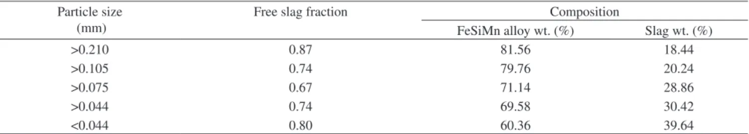
Table 3. Quantitative analysis of FeSiMn fines for slag and alloy content and the slag liberation fractions as a function of particle size.
Particle size (mm)
Free slag fraction Composition
FeSiMn alloy wt. (%) Slag wt. (%)
>0.210 0.87 81.56 18.44
>0.105 0.74 79.76 20.24
>0.075 0.67 71.14 28.86
>0.044 0.74 69.58 30.42
Vol. 11, No. 4, 2008 Characterization of Manganese Alloy Residues for the Recycling of FeSiMn and High-Carbon FeMn fines 407
more fines than the alloy. In the case of the HC-FeMn alloy parti-cles, the liberation of the slag was not quite as high as for FeSiMn, presenting free slag fractions as low as 0.56. However, in all particle size ranges, the alloy content was higher and the slag content lower than in the previous alloy. In the overall sample (<1.18 mm), it was observed that 95.07% was alloy and 4.93% was slag.
Quantitative analysis by optical microscopy of both the fines above 1.18 mm, confirmed that for HC-FeMn (>1.18 mm) there was 99.9% of alloy content and for FeSiMn fines (>1.18 mm) 99.8% was alloy.
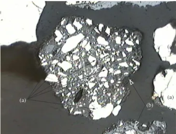
3.1. Microstructual examination
Figures 2 and 3 show typical microstructural examples, revealed under polarized light, of free and aggregated particles present in alloy fines, in which the predominant forms of interaction between alloy and slag can be seen. The alloy particles reflect light and are the shiny phase in the micrographs (a). The grey phase corresponds to the slag (b) and the dark features show either the presence of a fracture, or a pore, or a crystalline surface that is not perpendicular to the light rays (c). Figure 4 shows a free slag particle.
4. Conclusions
In the HC-FeMn fines, 52.12% of particles we re above 1.18 mm. In the FeSiMn, 51.93% of particles were above 1.18 mm. The HC-FeMn and FeSiMn fines above 1.18 mm had, respectively, 99.9 and 99.8% of alloy content. Therefore, a simple screening operation at 1.18 mm could be an efficient HC-FeMn and FeSiMn fines concen-tration procedure.
The Mn, Fe and Si concentrations in both the HC-FeMn and FeSiMn fines below 1.18 mm did not meet chemical composition specifications for steelmaking. Nevertheless, the phosphorus con-centration was acceptable in both fines samples.
In the FeSiMn and HC-FeMn fines samples below 1.18 mm, about 56% of the particles were smaller than 0.594 and 0.420 mm respec-tively. The FeSiMn and HC-FeMn fines samples below 1.18 mm had 87.95 and 95.07% of alloy respectively. As a general rule, the smaller the particles size the bigger the slag concentration.
The free slag fractions, obtained for HC-FeMn and FeSiMn fines below 1.18 mm are suitable for gravity concentration (now under study).
Acknowledgements
The authors would like to thank VALE for supplying samples and the Fundação Gorceix from Ouro Preto – Brazil, for financial support.
Table 4. Quantitative analysis of HC-FeMn fines for slag and alloy content and the slag liberation fractions as a function of particle size.
Particle size
(mm) Free slag fraction
Composition HC-FeMn
Alloy wt. (%)
Slag wt. (%)
>0.210 0.87 96.04 3.96
>0.105 0.58 74.48 25.52
>0.075 0.56 65.46 34.54
>0.044 0.58 65.21 34.79
<0.044 0.84 70.91 29.09
(b) (b)
(c)
(a)
Figure 2. Optical micrograph of a HC-FeMn alloy particle aggregated to slag. 220x. a) alloy, b) slag, and c) pore/fracture.
(a)
(b) (a) (a)
Figure 3. Optical Micrograph of FeSiMn alloy particles aggregated to slag. 220x. a) alloy, and b) slag.
(a) (b)
(a)
408 Faria et al. Materials Research
References
1. Ullmann F. Manganese and Manganese Alloys. In: Encyclopedia of Industrial Chemistry. 5ª edition. Weinhein, Germany: VCH; 1985. vol. 16 A, p.77-133.
2. Tangstad M, Olsen SE, Sverre, E. The Ferromanganese Process – Material and Energy Balance. In: 7 th International Ferroalloys Congress – INFACON; 1995. Trondheim, Norway: NTH-TRYKK; 1995.
3. Tangstad M. Production of Ferromanganese Alloys in the Submerged Arc Furnace. Trondheim, Norway: Tapir Academic Press; 2007.
4. Riss A, Khodorovsky Y. Production of Ferroalloys. Moscow: Mir Publishers;1967. p. 218-230.
5. Ding W, Kossyreva O, Olga A. Tangstad, M. Equilibrium in Production of High Carbon Ferromanganese. In: 7th International Ferroalloys Congress – INFACON;1995. Trondheim, Norway: NTH-TRYKK; 1995. p. 591-600.
6. Ding W, Olsen SE. Manganese and Silicon Distribution between Slag and Metal in Silicomanganese Production. ISIJ International 2000; 40(9):850-856.
7. Ding W. Equilibrium Relations in the Production of Manganese Alloys. [Doctoral thesis]. Trondheim, Norway: Norwegian Institute of Technology; Feb. 1993.
8. Faria G. Caracterização Química e Estrutural de Matérias-Primas e Produtos de Ferro Ligas de Manganês. [Monografia]. Ouro Preto: Departamento de Física – UFOP; 2006.
9. Silveira RC, Lucio A, Mines CRC, Figueira RM, Sampaio RS, Castro LFA. Metalurgia dos ferro-ligas. Belo Horizonte: Escola de Engenharia, Universidade Federal de Minas Gerais; 1980.