Autor Responsável: Dario Cardoso de Lima Data de envio: 03/08/2016 Data de aceite: 05/06/2017
10.1590/S1517-707620170003.0210
Rheology and mechanical aspects of a
self-compacting soil-cement in
the fresh state
Aspectos reológicos e mecânicos do estado
fresco de um solo-cimento autoadensável
Marco Antônio de Morais Alcantara1, Sandra Conceição Barbosa Nunes2, João Filipe Meneses Espinheira Rio3, Dario Cardoso de Lima4
1 Professor Assistente Doutor, Departamento de Engenharia Civil, Universidade Estadual Paulista “Júlio de Mesquita
Filho”, Ilha Solteira, São Paulo. e-mail: [email protected]
2
Professora Auxiliar Doutor, Departamento de Engenharia Civil, FEUP da Universidade do Porto, Rua Doutor Roberto Frias 4200, Porto-Portugal, 4200-465.
e-mail: [email protected]
3Professor Auxiliar Doutor,Departamento de Engenharia Civil, FEUP da Universidade do Porto, Rua Doutor Roberto
Frias 4200, Porto-Portugal, 4200-465. e-mail: [email protected]
4
Professor Titular, Departamento de Engenharia Civil, Universidade Federal de Viçosa, Viçosa, Brazil, CEP 36570 000; e-mail: [email protected]
ABSTRACT
The article presents a study of design parameters for the fresh self-compacting soil-cement so that it can be framed under the action of its own weight in the production of prefabricated elements.
In the experimental work, it was used a residual soil of the region of Porto, Portugal, Portland cement, water and an additive of steric and electrostatic actuation as superplasticizer.
The proportion of materials were related to soil dry weight with cement contents ranging from 20, 25, and 30%, water from 41, 44 and 47%, and superplasticizer from 0.66, 0.84 and 0.93%.
The tests performed on fresh state fit into assessment protocols used for self-compacting mortars and con-cretes, and refer to the spreading test using a mini cone and the flow test with the aid of a funnel. In the hard-ened state, it was performed the unconfined compression test.
The results indicated that the fresh self-compacting soil-cement falls technologically into the behavior ob-served in concretes and mortars, distinguishing the expressive influence of water and superplasticizer as flu-idity agents, and soil and cement as viscosity controlling agents. Amounts of these constituents were defined in order to better optimize the conditions of fluidity and mobility of the mixtures, which may have as primary parameter of dosage the water/cement ratio, with regard to mechanical strength, and the specimens apparent density. The properties of fluidity and mobility are preferably correlated with the water/(cement+soil) ratio. Keywords: self-compacting soil-cement, unconfined compression strength, rheology.
RESUMO
O artigo apresenta um estudo de parâmetros de projeto para o solo-cimento autoadensável, fluido, de maneira que este possa ser moldado sob a ação do seu peso próprio na produção de elementos pré-fabricados. No trabalho experimental, trabalhou-se com um solo residual da região do Porto, Portugal, cimento Portland, água e um aditivo de atuação estérica e eletrostática como superplastificante.
A proporção dos materiais foi adotada a partir do peso seco do solo, com teores que variaram de 20, 25, e 30% para o cimento, 41, 44 e 47% para a água e 0,66, 0,84 e 0,93% para o superplastificante.
e ao ensaio de fluidez com o auxílio do funil. No estado endurecido, foram realizados ensaios de resistência à compressão simples.
Os resultados do estudo indicaram que o solo-cimento autoadensável fluido insere-se tecnologicamente no comportamento observado em concretos e argamassas, sobressaindo-se a influência expressiva da água e do superplastificante como agentes de fluidez, bem como do solo e cimento como agentes controladores da vis-cosidade. Teores destes constituintes foram definidos de modo a otimizar as condições de fluidez e mobilida-de das misturas, que pomobilida-dem ter como parâmetro primário mobilida-de dosagem a relação água/cimento, no que tange à resistência mecânica, e na densidade aparente dos corpos de prova ensaiados. As propriedades de fluidez e de mobilidade podem ser preferencialmente correlacionadas com a relação água/(cimento+solo).
Palavras-Chave: solo-cimento autoadensável, resistência à compressão simples, reologia.
1. INTRODUCTION
In concept, the fluid soil-cement should be able to thicken under the action of its own weight, in a manner analogous to self-compacting concretes that, according to ALCÂNTARA [1], must be fluid without present-ing the segregation and exudation phenomena, and fill the molds easily without the presence of blockages.
FONSECA et al. [2] report that the determination of engineering properties of the self-compacting soil-cement is related to soil compaction factors, such as soil microstructure or fabric, amount of water and its influence on the compaction process, and the decrease in the soil voids volume. According to the authors, it is preferable to use the cement volume/soil void volume ratio as the dosage variable. The self-compacting soil-cement can be considered close to materials reported by HORPBILSUK et al. [3], where the amount of water embedded in the mixtures is high enough to relate to the amount of soil voids, similarly to what hap-pens in the case of the Portland cement concrete, where the amount of water reflects the amount of voids in the mortar phase. That is how it differs from traditional soil-cement.
Previous experience of producing non-compacted soil-cement is reported by SEGANTINI and ALCÂNTARA [4]. The authors refer to the plastic soil-cement designed to be compressed under the action of its own weight for use in the production of in situ molded piles but employing 4% of cement by weight above the suggested content commonly used in the design of soil-cement mixtures. It is emphasized that some types of soil, especially clayey soils, require high amounts of water to achieve the desired plastic con-sistency, similar to a plaster mortar. In these cases, the ideal design water/cement ratio should be less than 1 and the soil-cement mixtures viewed as an intimate mixture of soil constituents, cement, and water produced with the use of mechanical mixers.
BUSSIERE [5] presents the soil-cement slurry also titled Concresoil and proposes its application in the soil reinforcement of low bearing capacity soils. The author points out that the mechanical strength achieved by the soil-cement slurry is usually higher than that presented by natural soils, reinforcing its char-acter of a soil stabilization process. High-pressure injection and jet-grouting are processes related to the ap-plication of this technique that can produce columns with unconfined compressive strength up to 4 MPa. Considering the self-compacting properties of soil-cement mixtures fluidized by superplasticizer, BERTÉ [6] analyzed their self-compacting properties for engineering applications, in order to attend different require-ments of mechanical strength and durability. This author determined dosage parameters for Argisols from the West of the State of São Paulo, associating them with the properties of the soil-cement in the fresh and hard-ened states. In particular, he noted that variations in the fresh mixture properties were more related to the water/(cement+soil) ratio rather than to the water/cement ratio, as well as the value of the mechanical strength was associated with the water/cement ratio and the water absorption, and mixtures mechanical strength ranged from 2 to 7.5 MPa.
ALCÂNTARA et al. [7] report data from self-compacting soil-cement mixtures using residual soils from Porto, Portugal, focusing on the laboratory instrumentation set up. Data from this study support that the mechanical strength at 28 days of cure was crescent with the electrical resistivity and with the hydration of cement during curing. Consistently, the authors observed that the ultrasound propagation velocities were di-rectly related to the specimens' mechanical strength.
2. MATERIALS AND METHODS
A young residual soil (saprolite) from the city of Porto, Portugal, water, Portland cement CEM I 42.5, and steric and electrostatic action superplasticizer were used throughout the study.
The methodology considered the variation of the fluidifying agents, water, and superplasticizer, and viscosity conditions, as presented in Table 1, emphasizing that: (i) compositions 1, 2, 3, 4, and 5 have the same superplasticizer/soil ratio, differing in the cement/soil and water/soil ratios; (ii) compositions 1, 2 and 3 present the same cement/soil ratio, differing in the water/cement ratio; and (iii) compositions 1, 4, and 5 show the same water/soil ratio, differing in the cement/soil ratio. Table 2 introduces compositions 6 and 7, both designed with the same water/soil and cement/soil ratios, but differing in the superplasticizer/soil ratio.
Table 1: Compositions by weight adopted in the experimental study: case studies in which the superplasticizer-soil ratio remain constant and the cement/soil and water/soil ratios differ.
PARAMETER RATIOS MIXTURE 1 –
REFERENCE M1 (C20)
MIXTURE 2
M2 (C20, +W)
MIXTURE 3
M2 (C20, -W)
MIXTURE 4
M4 (C25)
MIXTURE 5
M5 (C30)
Soil (g) 1508.33 1508.33 1508.33 1508.33 1508.33 Cement CEM I
42.5
R-Secil-Maceira (g) 301.67 301.67 301.67 377.08 452.50 Water 663.67 708.92 618.42 663.67 663.67 Superplasticizer
(V3008) (g) 12.07 12.07 12.07 12.07 12.07 Water 1 (g) 530.93 567.13 494.73 530.93 530.93 Water 2 (g) 132.73 141.78 123.68 132.73 132.73 Relationships
between mixtures constituents
cement/soil 20% 25% 30%
water/soil 44% 47% 41%
superplasticizer/soil 0,84% 0,84% 0,84% 0,84% 0,84%
Table 2: Compositions by weight adopted in the experimental study: case studies in which the superplasticizer-soil ratio differ and the cement/soil and water/soil ratios remain constant.
PARAMETER RATIOS MIXTURE 1 –
REFERENCE M1 (C20)
MIXTURE 6
M6 (C20, -S)
MIXTURE 7
M7 (C20, +S) Soil (g) 1508.33 1508.33 1508.33 Cement CEM I 42.5
R-Secil-Maceira (g) 301.67 301.67 301.67
Water 663.67 663.67 663.67
Superplasticizer
(V3008) (g) 12.07 10 14
Water 1 (g) 530.93 567.13 494.73 Water 2 (g) 132.73 141.78 123.68 Relationships
between mixtures constituents
cement/soil 20% water/soil 44%
superplasticizer/soil 0,84% 0,66% 0,93%
Figure 1: The standardized procedure used for the mixing phase.
Once completed the mixing procedure, validation tests in the fresh state, free flowing scattering tests (slump-flow) and confined flow tests (funnel test) were carried out. After, specimen molding took place, pouring the contents of the mixer`s tub into specific molds, without the aid of vibration or any other mechan-ical force, counting exclusively with the energy provided by the mixture own weight. Frame molds, which enabled the manufacture of prismatic specimens of 4 x 4 x 6 cm, were used in specimen preparation, and three repetitions were adopted as standards in the experimental design. After molding, the prismatic speci-mens were taken to cure in the humid incubation chamber for a period of 28 days before performing uncon-fined compression tests.
Scattering (slump-flow) and V-funnel test were conducted for assessment of mixtures quality, respec-tively, under free and confined flowing conditions. NUNES [8] describes the procedure adopted during the scattering tests, as illustrated in Figure 2. In the test, the interior of the cone and the surface of the metal plate were dampened with a damp cloth; then, the plate was put on a firm, flat and level surface; after the end of the sample mixing operation, the cone was filled with the mixture, leveled at the top and raised vertically in a continuous and careful movement; at the end of the movement, maximum (D1) and perpendicular (D2) di-ameters of the scattering area formed were measured.
Figure 2: Measurement of scattering diameters (units in mm).
The V-funnel procedure test followed the procedure described by NUNES [8] and ALCÂNTARA [1], using a funnel with the dimensions presented in Figure 3. The test steps included: (i) moisten the inside of the funnel with damp cloth; (ii) place the funnel and supporting structure on firm, flat and leveled surface; (iii) position the container in order to receive the mortar and close the bottom hatch; (iv) continuously and with-out any kind of vibration, fill completely the funnel with the mortar; (v) level the mortar on the top and open the hatch, and simultaneously start the time count with a stopwatch; and (vi) observe the movement through the top and stop the time count with the appearance of the first points of light at the bottom of the funnel.
70 100 60 D1 D2 Cone lifting
Soil + cement + 0.81(total water)
Super plasticizer + 0.19(total water) mix 60 sec. speed slow mix 60 sec. speed slow mix 60 sec. speed slow mix 30 sec. speed slow mix 30 sec. speed fast wait 1 min.
Figure 3: Time assessment of the confined flow using the V-funnel (units in mm).
Unconfined compressive strength tests were performed in specimens molded from the dismember-ment of the 4x4x16 cm prism into four cubes using a control displacedismember-ment system at the loading speed of 0.01 m/s, according to the procedure described by IPQ [9], after the slight modifications proposed by NUNES [8].
In assessing the apparent density, the mixtures were poured into tablet molds, measuring the volume and weight of the material poured in order to determine their apparent densities.
3. RESULTS AND DISCUSSION
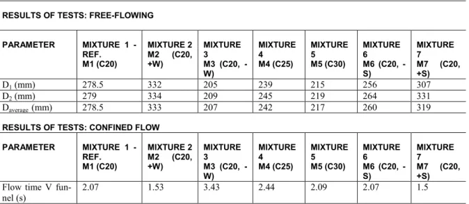
Table 3 presents the results of free flow (scattering) and confined (V-funnel) tests carried out in the fresh state.
Table 3: Results of free and confined flow tests performed in the fresh state.
RESULTS OF TESTS: FREE-FLOWING
PARAMETER MIXTURE 1 -
REF. M1 (C20)
MIXTURE 2 M2 (C20, +W)
MIXTURE 3
M3 (C20, -W) MIXTURE 4 M4 (C25) MIXTURE 5 M5 (C30) MIXTURE 6
M6 (C20, -S)
MIXTURE 7
M7 (C20, +S) D1 (mm) 278.5 332 205 239 215 256 307
D2 (mm) 279 334 209 245 219 264 331
Daverage (mm) 278.5 333 207 242 217 260 319
RESULTS OF TESTS: CONFINED FLOW
PARAMETER MIXTURE 1
-REF. M1 (C20)
MIXTURE 2 M2 (C20, +W)
MIXTURE 3
M3 (C20, -W) MIXTURE 4 M4 (C25) MIXTURE 5 M5 (C30) MIXTURE 6
M6 (C20, -S)
MIXTURE 7
M7 (C20, +S) Flow time V
fun-nel (s)
2.07 1.53 3.43 2.44 2.09 2.07 1.5
Figure 4 shows samples of the scattering surfaces obtained from the scattering tests, noticing that they were homogeneous and circular, without the presence of concentration areas, height irregularities in the dis-tribution of material, as well as without water halos, which would be indicative of segregation.
270
30 60
a b
Figure 4: Aspects of scattering surfaces obtained in the fresh state.
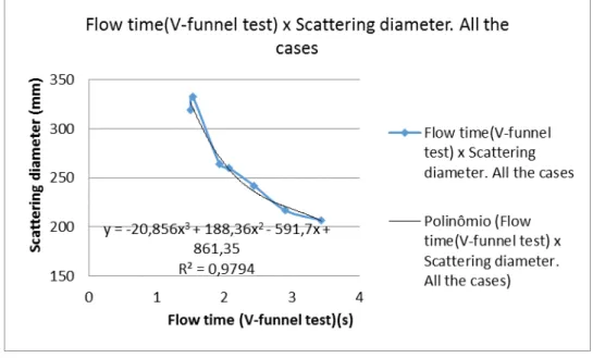
Figure 5 show data that illustrate the results of trials conducted under free and confined flow condi-tions for the cases analyzed in this study.
Figure 5: Comparison between data from scattering and V-funnel tests performed in the fresh state.
From Figure 5, it is observed that the free and confined flow tests data presented reverse images asso-ciated with the conditions of fluidity and viscosity, whereas the increased fluidity resulted in larger scattering diameters, in a free flowing, and in smaller flow times, in confined flow. Variation of conditions of cohesion and viscosity were relevant to support the observed behavior, and it was not noticed the expressive influence of friction between particles of larger diameter or inter-granular shocks.
Table 4: Dosage parameters of the studied compositions.
PARAMETER MIXTURE
1 M1 (C20)
2
M2 (C20, +W)
3
M3 (C20, -W)
4 M4 (C25)
5 M5 (C30)
6
M6 (C20, -S)
7
M7 (C20, +S)
water/cement 2.2000 2.3500 2.0500 1.7567 1.4667 2.2000 2.2000 water(cement+soil) 0.3667 0.3917 0.3417 0.3519 0.3385 0.3667 0.3667 water/soil 0.4400 0.4700 0.4100 0.4400 0.4400 0.4400 0.4400 superplasticizer/cement 0.0400 0.0400 0.0400 0.0319 0.0267 0.0331 0.0464 cement/soil 0.2000 0.2000 0.2000 0.2505 0.3000 0.2000 0.2000
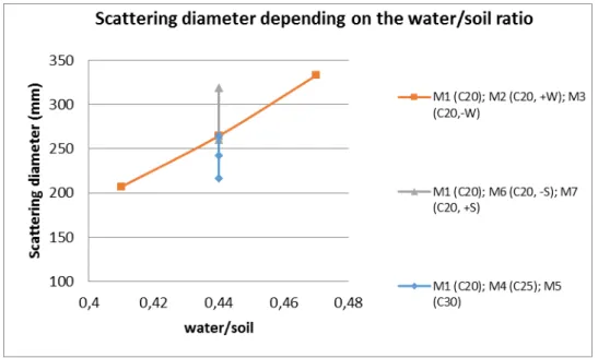
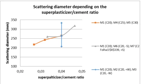
With respect to free flow, in the first phase of the study it was analyzed the variation of the scattering diameter with the dosage parameters, and in the second phase, it was quantified the percentage variation of diameter with the percentage variation of composition parameters. Figures 6 to 10 illustrate the variation of the scattering diameters with the composition parameters, emphasizing that only in mixtures 1, 2, and 3 the amount of water varied while maintaining constant the superplasticizer/cement, superplasticizer/soil and ce-ment/soil ratios.
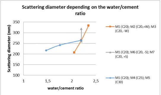
Figure 7: Variation of the scattering diameter with the water/cement ratio.
Figure 9: Variation of the scattering diameter with the superplasticizer/cement ratio.
Figure 10: Variation of the scattering diameter with the cement/soil ratio.
On the basis of the data presented in Figure 6, it was noted that the scattering diameter increased di-rectly with the added water content. In the reference mixture, mix 1, there was an alignment of points with cases of compositions 6 and 7, and 4 and 5, where the water/soil ratio was maintained fixed, denoting: (i) influence of superplasticizer content variations with relation to the soil and cement, with fluidization, as in compositions 6 and 7; and (ii) influence of variations of the cement/soil ratio and, indirectly, superplasticiz-er/cement, as in mixtures 4 and 5. The analysis of the three series supported that greater variation in the scat-tering diameter was caused by variation in the amount of water in the mixtures in comparison with the effect of the fluidifying additive or the cement.
Figure 8 shows close response between compositions 1, 2 and 3 and 1, 4 and 5, regarding the compo-sition parameter and scattering diameter variation, suggesting that flow conditions varied mainly with the variation of the water/(cement+soil), and, as illustrated in the case of the composition 7, suffered a localized effect when the superplasticizer content varied. In this case, the influence of the water/(cement+soil) ratio agreed with the cases of specific behavior of concrete and mortars, in accordance with BAUER [10] and BERTÉ [6].
Figure 9 illustrates the variation of scattering diameter with the variation of the superplasticiz-er/cement ratio while maintaining constant the cement/soil and water/soil ratios, as in compositions 1, 6 and 7, as well as indirectly with the variation of the cement/soil ratio while maintaining constant the superplasti-cizer/soil and water/soil ratios, as in mixtures 1, 4 and 5. Regarding variation of the superplasticizer/cement ratio, it was observed tendency to occur also the variation of the scattering diameter, due to the variation of the flow conditions. It was noticed that when the content of superplasticizer was fixed with the concomitant variation of the mix water content, as in compositions 1, 2 and 3, flow conditions suffered expressive modifi-cations, denoting water´s influence in flow conditions, as well as its effect acting in synergy with other mix-ture components.
In Figure 10, only in compositions 1, 4 and 5 were observed the influence of the cement/soil ratio in the scattering diameter where flow conditions were affected either by the cohesive effect of cement or by the change in the superplasticizer/cement ratio. In the cases of the other series, i. e. compositions 1, 2, and 3 and 1, 6 and 7, the cement/soil ratio remained constant, and the fluidization occurred due to the variation of wa-ter/soil and water/cement ratios, as in compositions 1, 2 and 3, and superplasticizer/soil and superplasticiz-er/cement ratios, as in compositions 1, 6 and 7, reflecting once again the influence of the incorporation of water into the mix on the variation of the scattering diameter.
Based on the analysis of the results of Figures 6 to 10, it was observed that water, superplasticizer, and cement played different rules as fluidization agents, being the first two essentially fluidizers and the latter a cohesion agent. It was concluded that water and superplasticizer could act in synergy in order to intensify the process, as well as that cement could affect the viscous properties of self-compacting soil-cement. Possible variations when weighing these materials can influence the quality of the final product, responding for lower or higher mixture fluidization; on the other hand, the different paths analyzed in this study may indicate tra-jectories of greater efficiency. In addition, Table 5 presents the percentage changes in the values of scattering diameter for the analyzed mixtures as well as the percentage variations of composition parameters.
Table 5: Percentage variation in the values of the scattering diameter, composition parameters and ratios among the per-centage values associated with the free flow condition of the analyzed mixtures.
MIXTURES 1 M1(C20)- 2 M2 (C20, +W) - 3 M3 (C20,-W)
MIXTURES 1 M1 (C20) - 4 M4(C25) - 5 (C30)
MIXTURES 1 M1(C20)-6 M6(C20,-S) - 7 M7(C20,+M6(C20,-S)
MIXTURES 1 - 2 MIXTURES 1 -3 MIXTURES 1-4 MIXTURES 4-5 MIXTURES 1-7 MIXTURES
1-6 Percentage variation in the scattering diameter (%)
19.21 35.85 16.53 11.16 10.23 8.79
Percentage variation in the water/cement ratio (%)
6.82 7.32 25.24 19.77 0 0
Percentage variation in the scattering diameter (%)/percentage variation in the water/cement ratio (%)
2.82 4.9 0.65 0.56 - -
Percentage variation in the water/(cement+soil) ratio (%)
6.82 7.32 4.21 3.96 0 0
Percentage variation in the scattering diameter (%)/percentage variation in the water/(cement+soil) ratio (%)
2.82 4.9 3.93 2.82 - -
Percentage variation in the water/soil ratio (%)
6.82 7.32 0 0 0 0
Percentage variation in the scattering diameter (%)/percentage variation in the water/soil ratio (%)
2.82 4.9 - - - -
Percentage variation in the superplasticizer/cement ratio (%)
0 0 25.24 19.77 15.99 20.70
Percentage variation in the scattering diameter(%)/percentage variation in the superplasticizer/cement ratio (%)
- - 0.65 0.56 0.64 0.42
Percentage variation in the cement/soil ratio (%)
Percentage variation in the scattering diameter (%)/percentage variation in the cement/soil ratio (%)
- - 0.65 0.56 - -
Based on the analysis of data from Table 5, it was observed that: (i) the percentage variation of the water/cement ratio exercised greater influence over the percentage variation of the scattering diameter in compositions 1, 2 and 3 than in compositions 1, 4 and 5, in accordance with data presented in Figures 6 - 10; and (ii) the values of the relation between the percentage variation of the scattering diameter and the percent-age variation of the water/(cement+soil) ratio showed lower dispersion, in compositions 1, 2 and 3 and 1, 4 and 5.
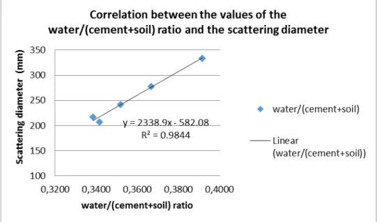
Figures 11 and 12 illustrate, respectively, correlations between the scattering diameter and the wa-ter/cement and the water/(cement+soil) ratios for the case of free flowing. It was shown that the variation in the scattering diameter was significantly influenced by the variation of the water/(cement+soil), as in Figure 12, with a coefficient of determination of 0.9844, i.e., only 0.0156% of the regression variance did not de-pend on the analyzed variables.
Figure 11: Correlation between the values of the water/cement ratio and the scattering diameter for the case of free flow.
Figure 13 presents the correlation between the scattering diameter and the superplasticizer/cement ratio in free flow condition, concluding that there was a significant correlation with a coefficient of determi-nation of 0.9639.
Figure 13: Correlation between the values of the superplasticizer/cement ratio and the scattering diameter for the case of free flow.
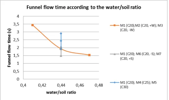
Figures 14 to 18 bring data that illustrate the behavior of mixtures in confined flow, similarly to the way adopted in the case of free flow. Considering that these two types of flow have inverse images, it was observed that instead of an increase of the scattering diameter, occurred a reduction of the flowing time into the funnel. A similar effect can occur by the influence of the compositional parameters as in the case of free flow.
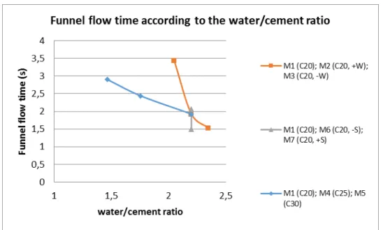
Figure 15: Variation of the funnel flow time with the water/cement ratio in the confined flow.
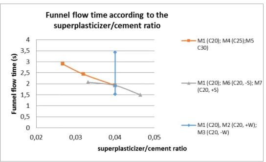
Figure 17: Variation of the funnel flow time with the superplasticizer/cement ratio in the confined flow.
Figure 18: Variation of the funnel flow time with the cement/soil ratio in the confined flow.
Table 6: Percentage variation among values of the funnel flow time, composition parameters and ratios among the per-centage values under confined flow.
MIXTURES 1 M1(C20)- 2 M2 (C20, +W) - 3 M3 (C20,-W)
MIXTURES 1 M1 (C20) - 4 M4(C25) - 5 (C30)
MIXTURES 1 M1(C20)-6 M6(C20,-S) - 7 M7(C20,+S)
MIXTURES 1-2 MIXTURES 1-3 MIXTURES 1-4 MIXTURES 4-5 MIXTURES 1-7 MIXTURES 1-6
Percentage variation in the funnel flow time (%)
35.29 80 17.87 16.75 38 0
Percentage variation in the water/cement ratio (%)
6.82 7.32 25.24 19.77 0 0
Percentage variation in the funnel flow time (%)/Percentage variation in the water/cement ratio (%)
5.18 10.94 0.71 0.85 - -
Percentage variation in the water/(cement+soil) ratio (%)
6.82 7.32 4.21 3.96 0 0
Percentage variation in the funnel flow time (%)/Percentage variation in the water/(cement+soil) ratio (%)
5.18 10.94 4.25 4.23 - -
Percentage variation in the water/soil (%)
6.82 7.32 0 0 0 0
Percentage variation in the funnel flow time (%)/ Percentage variation in the water/soil (%)
5.18 10.97 - - - -
Percentage variation in the superplasticizer (%)/cement ratio (%)
0 0 25.24 19.77 15.99 20.70
Percentage variation in the funnel flow times (%)/Percentage variation in the superplasticizer/cement ratio (%)
- - 0.71 0.85 2.38 -
Percentage variation in the cement/soil ratio (%)
0 0 24.24 19.77 0 0
Percentage variation in the funnel flow time (%)/Percentage variation in the cement/soil ratio (%)
- - 0.71 0.85 - -
Figures 19 to 21 depict correlations between the funnel flow time and the water/(cement), wa-ter/(cement+soil) and superplasticizer/cement ratios under confined flow. Similarly to the case of free flow, it was observed that the water/(cement+soil) and superplasticizer/cement ratios presented the best correlations with variations in the funnel flow time, however with a lower coefficient of determination.
Figure 20: Correlation between the water/(cement+soil) ratio and the funnel time in confined flow.
Figure 21: Correlation between the water/cement ratio and the funnel flow time in confined flow.
Table 7 shows the apparent density reached by mixtures in the hardened state five days after demold-ing.
Table 7: Apparent density reached by the mixtures in the hardened state.
PARAMETER MIXTURE
1-REF. M1 (C20)
MIXTURE 2
M2 (C20, +W)
MIXTURE 3
M3 (C20, -W)
MIXTURE 4 M4 (C25)
MIXTURE 5 M5 (C30)
MIXTURE 6
M6 (C20, -S)
MIXTURE 7
M7 (C20, +S) Apparent density
(g/cm3)
1.934 1.798 1.954 2.015 1.989 1.816 1.935
Table 8: Results of unconfined compressive strength tests performed in the hardened state after 28 days of cure.
PARAMETER MIXTURE
1-REF. M1 (C20)
MIXTURE 2 M2 (C20, +W)
MIXTURE 3 M3 (C20, -W)
MIXTURE 4 M4 (C25)
MIXTURE 5 M5 (C30)
MIXTURE 6 M6 (C20, -S)
MIXTURE 7 M7 (C30, +S)
UNCONFINED COMPRESSIVE STRENGTH (MPA)
Average value (MPa)
3.170 2.704 3.735 4.856 6.492 2.926 3.172
Standard deviation
0.109 0.071 0.113 0.203 0.250 0.175 0.049
Coefficient of variation
3.439 2.618 3.022 4.178 3.843 5.984 1.529
Preliminary analysis involving the values of the unconfined compressive strength and the others com-position parameters presented in Table 4 showed that changes in the unconfined compressive strength are basically dependent on the water/cement ratio. Therefore, Figure 22 associates unconfined compressive strength and water/cement ratios, and Figure 23 presents data from regression analysis incorporating both parameters.
Figure 23: Correlation between the unconfined compressive strength and the water/cement ratio.
Based on the results presented in Figure 23, it was observed that the unconfined compression strength was inversely correlated with the water/cement ratio as in the cases of concretes and mortars reported by BAUER [10].
Figure 24: Variation of the scattering diameter with the unconfined compressive strength.
Figure 25: Variation of the scattering diameter with the apparent density
On the other hand, in Figures 24 and 25, there was no significant correspondence between the un-confined compression strength and the apparent density with the scattering diameter. It was found that the value of the apparent density of the composition 5 was smaller than of the composition 4, but with higher unconfined compressive strength. This behavior could be related to possible physical and chemical condi-tions of soil flocculation, especially regarding the increase of cement amount in composition 5, when the su-perplasticizer/cement ratio became smaller than in the previous cases, influencing negatively the apparent density.
Similarly as in the case of the free flow, Figures 26 and 27 present relationships between the funnel flow time and the unconfined compressive strength and the apparent density, respectively.
Figure 26: Variation of the funnel flow time with the unconfined compressive strength
Figure 27: Variation of the funnel flow time with the apparent density
4. CONCLUSIONS
In this paper, a comprehensive laboratory testing program was undertaken to analyze the design parameters for the fresh self-compacting soil-cement. It was concluded that: (i) the flow properties kept strong correla-tion with the water/(cement + soil) and superplasticizer/cement ratios; (ii) the unconfined compressive strength values were correlated with the water/cement ratio, varying from 2.7 to 6.5 MPa, supporting that there is similarity of mechanical behavior between the self-compacting soil-cement and concretes and mor-tars; (iii) water, as well as the superplasticizer, proved to be excellent fluidifying agent, while cement and soil acted as a viscosity agent; and (iv) parameters determined in the fresh state kept an indirect relationship with those of mechanical strength, considering the apparent density reached in the blends, as well as the nature of the mixture paste.
5. ACKNOWLEDGEMENTS
The authors would like to thank UNESP, through its Graduate Improvement Program, for the financial aid for the realization of this study, and to the FEUP - University of Porto and LABEST, for the support for car-rying out this research.
6. BIBLIOGRAPHY
[1] ALCÂNTARA, M.A.M. Bétons auto-plaçants et fibrages hybrides: composition, rhéologie et
comporte-ment mécanique, Degree Ph.D., Institut National des Sciences Appliquées – INSA, Toulouse, France, 2004.
[2] FONSECA, A.V., CRUZ, R.C., CONSOLI, N.C. “Strength properties of sandy soil-cement admixtures”,
Journal of Geotechnical & Geological Engineering, v. 27, n. 6, pp. 681-686, Nov. 2009.
[3] HORPBILSUK, S., MIURA, N., NAGARAJ, T. S., “Assessment of strength development in cement-admixed high water content clays with Abram's law as a basis”,Geotechnique, v. 53, n. 4, pp. 439–444, Jan. 2003.
[4] SEGANTINI, A.A.S., ALCÂNTARA, M.A.M. ”Solo-cimento e solo-cal”, In: Isaia, G.C. (ed), Materiais
de construção civil e princípios básicos de ciência e engenharia de materiais, cap. 27, São Paulo, Brasil,
IBRACOM, 2007.
[5] BUSSIERE, J., “Soil-cement slurry strengthens weak soils”, Structure Magazine, pp. 24-24, Feb. 2010. [6] BERTÉ, S.D.D., Caracterização do solo-cimento auto-adensável, Dissertação de M.Sc., FEIS/UNESP, Ilha Solteira, SP, Brasil, 2012.
[7] ALCÂNTARA, M.A.M., NUNES, S.C.B., RIO, J.F.M.E., “Estudo do solo-cimento-autoadensável produ-zido com solos da região do Porto-pt. Parte II: avaliação da resistência e desempenho mecânico por meio da medição da resistividade elétrica e velocidade de propagação de ondas de ultrassom”, Revista Eletrônica de
Engenharia Civil- REEC, v. 9, n. 1, pp. 52-64, Set. 2014.
[8] NUNES, S.C.B., Betão auto-compactável: tecnologia e propriedades, Dissertação de M.Sc., Faculdade de Engenharia da Universidade do Porto, Porto, Portugal, 2001.
[9] INSTITUTO PORTUGUÊS DE QUALIDADE – IPQ, NP EM 196-1: Métodos de ensaios de cimentos. Parte 1: determinação das resistências mecânicas, Monte de Caparica, Portugal, 1996.