Nat. Hazards Earth Syst. Sci., 11, 3197–3212, 2011 www.nat-hazards-earth-syst-sci.net/11/3197/2011/ doi:10.5194/nhess-11-3197-2011
© Author(s) 2011. CC Attribution 3.0 License.
Natural Hazards
and Earth
System Sciences
Experimental, numerical and analytical modelling of a newly
developed rockfall protective cable-net structure
S. Dhakal1,*, N. P. Bhandary2, R. Yatabe2, and N. Kinoshita2
1Graduate School of Science and Engineering, Ehime University, Matsuyama, Japan 2Department of Civil and Environmental Engineering, Ehime University, Matsuyama, Japan *currently on study leave: Nepal Engineering College, Pokhara University, Bhaktapur, Nepal
Received: 1 August 2011 – Revised: 13 September 2011 – Accepted: 26 October 2011 – Published: 7 December 2011
Abstract. An innovative configuration of pocket-type rock-fall protective cable-net structure, known as Long-span Pocket-type Rock-net (LPR), has been developed in Japan. The global performance of the proposed system was initially checked by the experimental (full-scale) modelling. Given the various limitations of the physical experiments, particu-larly for the parametric study to have a detailed understand-ing of the newly developed system, a reliable and simpli-fied method of numerical modelling is felt necessary. Again, given the sophistication involved with the method of numer-ical simulation, a yet simplified modelling approach may prove more effective. On top of this background, this pa-per presents a three-tier modelling of a design of LPR. After physical modelling, which has revealed that the displacement response may be taken more vital for LPR performance, Fi-nite Element based numerical modelling is presented. The programme LS-DYNA is used and the models are calibrated and verified with the element- and structure-level experi-ments. Finally, a simple analytical modelling consisting of the equivalently linear and elastic, lumped-mass, single-degree-of-freedom system, capable of predicting the global displacement response, is proposed based on the basic prin-ciples of conservation of linear momentum and energy. The model is back-calculated and modified from the analyses of the verified numerical model.
1 Introduction
Rockfall is an important geo-hazard of mountainous ter-rains around the globe and is gaining increased attention and recognition due primarily to the severe accidents and mortali-ties in mountain-highways and -railways, and even buildings,
Correspondence to:S. Dhakal ([email protected])
for instance, in the Alps. Despite being a small-volume haz-ard, it has been covering a wide range of technical and sci-entific literatures. Rockfall analysis/simulation (e.g. Giani, 1992; Evans and Hungr, 1993; Azzoni et al., 1995; Giani et al., 2004; Ushiro, 2006) characterises the various possible block trajectories and yields the information, such as run-out lengths, bounce heights, impact velocities and energies. Several computer programmes have already been developed and tested to simulate rockfall either by a lumped mass or a rigid body, 2-D or 3-D approach (Guzzetti et al., 2002) with or without considering the vegetation effects explicitly (e.g. Dorren and Berger, 2005; Masuya et al., 2009). A good deal of literature is also available which analyses the risk from rockfall hazard (e.g. Bunce et al., 1997; Crosta and Agliardi, 2003; Guzzeti et al., 2003; Peila and Guardini, 2008). Rock-fall simulation and/or the risk analysis ultimately become useful for the land-use planning (a guidance on landslide sus-ceptibility, hazard and risk zoning for land-use planning can be found in Fell et al., 2008a, b), and for the selection, lo-cation and dimensioning of the passive mitigation (protec-tive) structures when the land-use planning cannot avoid the hazard area or when the existing assets are to be preserved (Vogel et al., 2009). In fact, active mitigation (preventive) measures, such as rock-bolting, shotcreting, scaling, gluing, wire-meshing/drapery meshing, blasting, etc. may help, but they are not easy to execute and their effectiveness is diffi-cult to quantify by means of stability analyses or visual ob-servations (Descoeudres et al., 1999), thereby emphasizing the research expedition on protective measures.
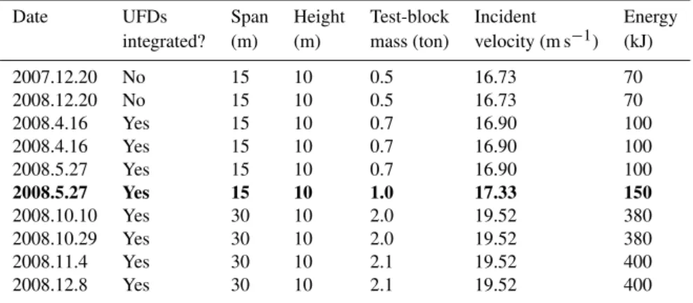
Table 1.The chronological list of the full-scale tests of various LPRs in the past verification and demonstration campaign. The highlighted case of the 15 m span, 150 kJ designated impact energy capacity is taken as a reference case LPR in the present study.
Date UFDs Span Height Test-block Incident Energy
integrated? (m) (m) mass (ton) velocity (m s−1) (kJ)
2007.12.20 No 15 10 0.5 16.73 70
2008.12.20 No 15 10 0.5 16.73 70
2008.4.16 Yes 15 10 0.7 16.90 100
2008.4.16 Yes 15 10 0.7 16.90 100
2008.5.27 Yes 15 10 0.7 16.90 100
2008.5.27 Yes 15 10 1.0 17.33 150
2008.10.10 Yes 30 10 2.0 19.52 380
2008.10.29 Yes 30 10 2.0 19.52 380
2008.11.4 Yes 30 10 2.1 19.52 400
2008.12.8 Yes 30 10 2.1 19.52 400
full-scale physical modelling or numerical modelling, can be traced from Smith and Duffy (1990), Peila et al. (1998), Gerber (2001), Nicot et al. (2001), Cazzani et al. (2002), Grassl et al. (2002), Volkwein (2004, 2005), Muhunthan et al. (2005), Muraishi et al. (2005), Maegawa (2006), Sasiha-ran et al. (2006), Castro-Fresno et al. (2008), EOTA (2008), Peila and Ronco (2009), and Gottardi and Govoni (2010). Over the evolution of time, these systems have been sub-jected to changes in their configuration and/or composition to enhance their performance and/or capacity, offsetting the disadvantages or limitations of the prevailing designs. In-troduction of highly flexible barriers of capacity as high as 5000 kJ in Europe such as in Switzerland, Italy and France, and hybrid barrier-drape system/attenuator (e.g. Badger et al., 2008) and “pocket-type rock-net” (Japan Road Associ-ation, 2000; Tajima et al., 2009), respectively, in the USA and Japan are among a few notable developments. The re-search towards better understanding and standardization of the drapery meshes (or wire-meshes or rock covering wire nets) (e.g. Yoshida, 1999; Muhunthan et al., 2005; Bertolo et al., 2009) are also continuing in parallel to the development of new flexible barrier (cable-net) systems.
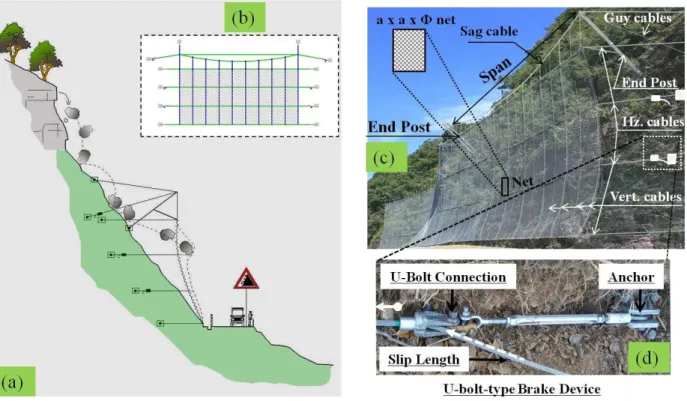
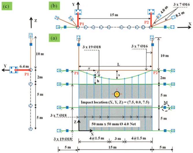
Recently in Japan, a new configuration of pocket-type rockfall protective cable-net barrier has been developed and named “Long-span Pocket-type Rock-net” (Kinoshita, 2009; Dhakal et al., 2011a), hereafter referred to as LPR. The structure is proposed for its effective application in low-to-medium rockfall hazard sites with limited clearance be-tween the road carriageway and hill-slope. For the time being, through a limited number of test-verifications (Ta-ble 1), the LPRs of a span up to 30 m and the correspond-ing design impact energy capacity of 400 kJ have been de-veloped. Figure 1 portrays the steel structure of a typical LPR. It essentially consists of wire-net (mesh), reinforcing and connecting horizontal-, vertical- and sag-cables (wire-ropes) and additional energy dissipating brake devices (pre-cisely, the U-bolt-type Friction-brake energy dissipating De-vices: UFDs) as the main impact resilient components. The
overall cable-net system is supported over the slanted posts (standard rolled steel sections) at either end, and all the hori-zontal and post-supporting guy-cables are firmly anchored to the ground (slope).
S. Dhakal et al.: Modelling a newly developed rockfall protective cable-net structure 3199
Fig. 1.LPR structure.(a): schematic sectional side view of a typical LPR structure intercepting the falling rock-boulder in a mountain-road.
(b): front elevation of the typical LPR.(c): LPR structural components illustrated over a picture taken from the real field installation.(d): a UFD installed in the LPR; shown schematically in(c).
developed, tested and used independently. However, they have a different composition, different reinforcing and sup-porting system for wire-net, possibly different brake devices and arrangements, etc. Furthermore, the mechanism of inter-ception is also different as there is as such no “tail” like con-struction in LPR system and the whole energy of the falling rock-block is required to be intercepted by the barrier itself like in a “fence”. Therefore, the available database for Hy-brid Drapery may not be useful in the study of the newly de-veloped LPR structure and a separate research is necessary.
The global performance of the proposed LPR structural system was evaluated by the full-scale physical modelling. Given the various limitations of the full-scale modelling (e.g. Cazzani et al., 2002; Volkwein, 2005; Miranda et al., 2011), particularly for the parametric study necessary to have the detailed understanding and characterisation of the newly de-veloped system, the method of numerical modelling is felt to be necessary. Again, by virtue of the sophistication involved in the numerical modelling, it may not be always practica-ble and/or sufficient as well, for instance, with regard to the requirements of own sanity check by the design engineers (Lam et al., 2010). Thus, a simplified modelling approach may yet prove more effective. Encouraged by the mentioned need, a three-tier modelling is discussed in this work. In fact, with the increasing applications of this structure inside Japan and having that similar structure is likely to be developed out-side as well; there is an important step in LPR research next
door – the preparation of the design code of practice for the structure. Additionally, having newly conceived only a lim-ited number of geometries and configurations that have so far been test-verified, there could have been a number of oppor-tunities left to optimize or improve the proposed design. Fur-thermore, with the easily replicable and verified numerical and/or analytical modelling described in the present work, investigation on various confusions and gaps revealed from the state-of-the-art literatures, for example, on the character-isation of rockfall impact loading onto a protective cable-net system (Cazzani et al., 2002; Cantarelli et al., 2008; Volk-wein et al., 2009) or possibly in any generic system (Yang et al., 2011), may be conveniently accomplished.
2 Full-scale modelling (FM)
3200 S. Dhakal et al.: Modelling a newly developed rockfall protective cable-net structure
“ “with
“
”
“
”
“
”
“
”
“
”
“
”
“
”
“
”
“
–
–
”
Please replace “ ”
“
”
“ ”
Please replace “
”
“
”
“
”
“
”
“
”
“
”
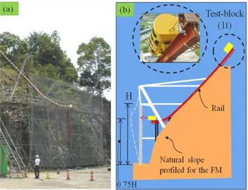
Fig. 2. The FM set up in the LPR test campaign. (a): a picture taken from the FM test site in Kochi, Japan (2008.5.27). (b): sec-tional side view illustrating the test set-up. Picture of cylindrical block used in the test is also shown. This block is released from a predefined height at the top of the rail, and traversing along the ideally frictionless rail, it hits the net at the specified point (0.75 H in the mid-span).
is highlighted in Table 1 and may be found referred to as R-LPR hereafter.
2.1 Test set up and the procedure
Figure 2 illustrates the FM set up and situation of the R-LPR. A cylindrical reinforced concrete block of a certain geome-try (length to diameter ratio of 2) was assumed as an ide-alized rock-block. The block weighing 1 ton was released from a certain height and guided over the specially manu-factured rail positioned onto a profiled hill-slope so that it hit the wire-net with a predetermined velocity of 17.33 m s−1 (kinetic energy of 150 kJ) horizontally (i.e., perpendicular to the net) at the specified impact point (Japan Road Associ-ation, 2000) located at mid-span, 3/4th height of wire-net equalling to 7.5 m. In fact, the possibility of other possi-ble worst scenarios of idealized rock-block shapes or sizes or impact points may be questioned here, but that exploration is beyond the scope of this paper, but may be found briefly discussed in Dhakal et al. (2011b).
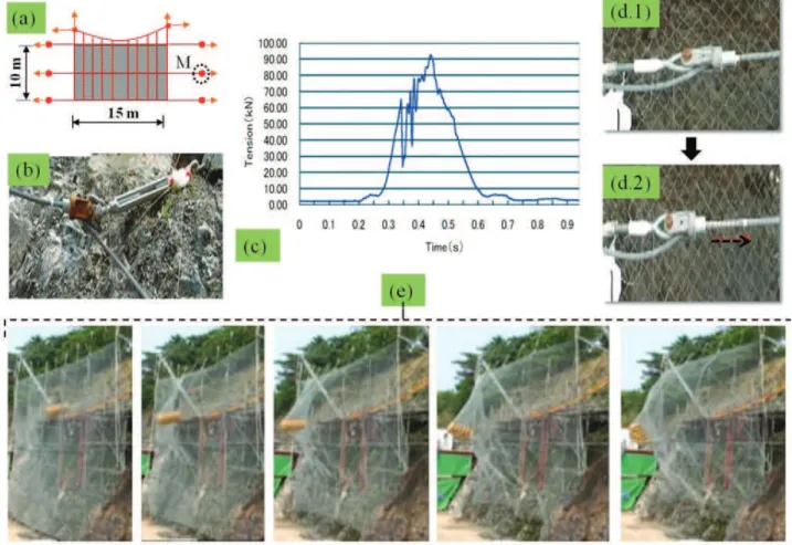
The set up was installed with the load-cells (strain gauges) in the cables in front of anchors to measure the tension developed in the cables or dissipators, while the motion and displacement-related measurements were monitored and framed by the high-speed video cameras; the magnitudes having calculated later on by the image processing. Figure 3 illustrates some important aspects as was observed and in-strumented in the FM.
2.2 Test results
The cable tension and the out-of-plane displacement have been considered to be the most important response quanti-ties to check the force and displacement performance crite-ria, while the information on slip-displacements of the brake elements (UFDs) may be necessary to evaluate their effi-ciency. In fact, the wire-net (wire-mesh) of the structure is purposefully made strong, and as witnessed in the past test campaign or in the various rockfall case histories afterwards, it is assumed that there shall be hardly any problem of per-foration or cutting effects of net by rock-boulders. Thus, in the FM (or the corresponding NM detailed in Sect. 3), only the aforementioned three response quantities have been de-scribed explicitly by the authors. Furthermore, because LPR is to be installed just beside the road with limited space be-tween the hill-slope and the carriageway, displacement based performance criteria (serviceability criteria) may be more vi-tal, given that the stresses are within safe limits. This may be a typical consideration in LPR unlike other types of rock-fall protective flexible barriers or fences devised in Europe or elsewhere.
S. Dhakal et al.: Modelling a newly developed rockfall protective cable-net structure 3201
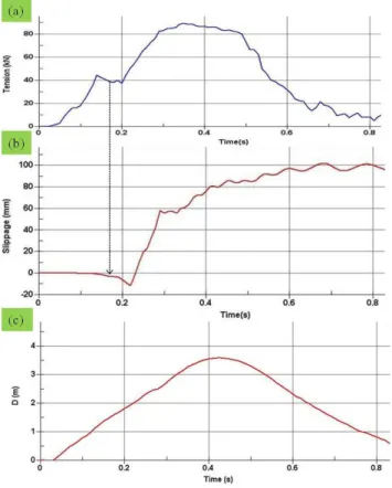
Fig. 3.Observation and instrumentation in the FM of R-LPR.(a): simple schematic front elevation of R-LPR, with the location of maximum cable tension or corresponding UFD slip-length shown by circle at M.(b): load cell or strain gauge installed just before anchor, which sends the tension developed in the cable near UFD to the data logger computer system (not shown). (c): time history of maximum cable tension instrumented by load cell at M. (d1) a UFD before slip. (d2) the same UFD after slip.(e): sequence of images of LPR deformation shown at an interval of 0.10 s, captured by the high-speed video cameras (not shown); the respective out-of-plane deformation was recorded approximately to evolve up to 3.5 m through 0.0 m, 0.5 m, 1.5 m and 2.5 m.
3 Numerical modelling (NM)
The LPR structure may be one of the ideal situations to apply the numerical method of Finite Element (FE) modelling and simulation. The straight-forward simplification in structural modelling and characterisation of this structure to study by simplified analytical formulae is virtually impossible owing to the fact that the structure involves a complex composition and interaction between its various impact resilient compo-nents, mainly the cable, the wire-net and the dissipators. This necessitates the employment of a numerical method as capa-ble as ordinary FEM (e.g. Reddy, 2004; Dhakal et al., 2011c). Moreover, the continuum method of FEM should be suffi-cient as well, due to the very fact the wire-net being purpose-fully made very strong, either cutting or perforation has not been evident. This may justify that a particle method such as the Smoothed Particle Hydrodynamics, SPH (Fukazawa et al., 2010) is not required to be considered in the study.
Fig. 4.Geometry and composition of R-LPR model with acceptable approximations.(a): front elevation showing the local coordinates axes (x,y) of parabolic sag-cable and global axes (X,Z) of system geometry.(b): top view on X-Y plane.(c): side elevation on Y-Z plane viewed from left (negative X axis).
3.1 Model geometry and composition
In fact, the orientations of posts and guy-like supporting ca-bles outward from the posts toward the anchors vary from case to case which may be observed both in the various proto-types considered in the past test campaign as well as the real constructions in the field implementation afterwards, mainly attributed to the existing topography of the hill-slope. More-over, it has been understood that these members primarily act as the restraints to the main cable-net-dissipator struc-tural system – the limelight of the study – and that they are relatively less stressed as well. Also, again based on the past observations or assumption of a careful foundation soil in-vestigation or necessary strengthening, the authors assume that the bearing capacity of each anchor foundation is well above the highest stresses by rockfall impact. Therefore, any generalized orientation of theirs should be acceptable unless, hypothetically, we are to focus our study on the supporting members themselves. This assumption should not have a
considerable effect in the main impact resilient structural sys-tem. In the present attempt to numerically model the R-LPR, the authors assumed the corresponding supporting members lay only on the horizontal and vertical planes. The approxi-mated configuration, together with the details of the overall structural geometry as well as the composition of the struc-ture is shown in Fig. 4.
The initial geometry (catenary shape) of the sag cable has been approximated by a parabolic curve due to having a lower value of sag (say, less than or equal to one tenth of the span as considered in the design and observed in the field). With the origin of coordinates of the parabola being at either of the end-posts (also shown in Fig. 4), the y-coordinates of the sag-cable parabola having spanLand design sags are given by Eq. (1).
y=4sx(L−x)
L2 (1)
S. Dhakal et al.: Modelling a newly developed rockfall protective cable-net structure 3203
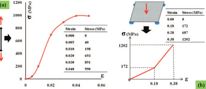
Fig. 5.Nonlinear stress-strain curves of cable(a)and shell equivalent wire-net(b).
top edge) may be obtained by subtracting the y-ordinates (y) of the parabola from 2 m. Thus, the lengths of the hangers (h) from left to right, corresponding to the x-coordinates (x): 0.0 m, 1.5 m, 3.0 m, 4.5 m, 6.0 m, 9 m, 10.5 m, 12 m, 13.5 m and 15.0 m, come out to be respectively 2.00 m, 1.52 m, 1.04 m, 0.80 m, 0.56 m, 0.56 m, 0.80 m, 1.04 m, 1.52 m and 2.00 m. The larger segment of 3 m in the middle portion was meant for the direct impact of the test block onto the wire-net for worst impact scenario for local damage/perforation, if any.
3.2 Choice of finite elements, material models and their calibration
The wire-net (mesh) was modelled equivalently by Belytschko-Tsay shell elements with Fabric material model (MAT 034), as a computationally efficient alternative to Hughes-Liu shell elements (Hallquist, 2006). The choice of Fabric material model was encouraged from the fact that, “in addition to being a constitutive model, this model also invokes a special membrane element formulation which is more suited to the deformation experienced by fabrics un-der large deformation” (LSTC, 2007). The nonlinear stress-strain curve was obtained accordingly via a slab-like panel test of the net (Fig. 5b). The cables were modelled by Discrete Beam Cable elements and their nonlinear material model (MAT 071) was calibrated with the piecewise lin-ear stress-strain curve data obtained from the uniaxial ten-sile test (Fig. 5a). The posts were modelled by Discrete Beam element with the elastic-linearly plastic, isotropic hardening material model having the properties of the or-dinary steel (yield stress=300 MPa and hardening param-eter (Et/E)=0.1). The corresponding sectional properties
(such as cross-sectional area, moments of inertia, etc.) were assigned subsequently as defined in the programme’s user
manual (LSTC, 2007). The density of any steel member is considered the same and a constant value of 7840 kg m−3. The cross-sectional areas of the various cables used in the R-LPR are 163 mm2, 140 mm2 and 125 mm2, respectively, for the (7×19×188), (3×7×188) and (3×7×168)
cables. The weight per unit area and the thickness of the equivalent shells of the wire-net are, respectively, 4.6 kg m−2 and 0.587 mm.
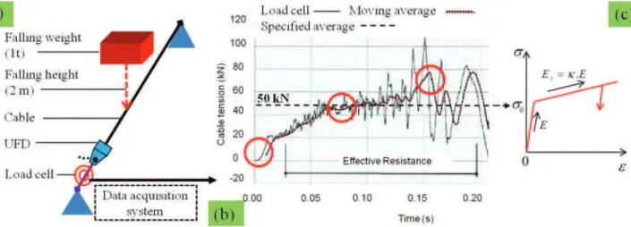
Fig. 6.Constitutive modelling of UFD.(a): the scheme of FWT set up for an isolated UFD conducted by Besafe (2006). (b): the recorded time history of cable tension together with the 200-moving-point average curve and specified average slip-tension value shown. Also shown are the milestones in the history shown by circles. (c): the assumed constitutive model for UFD-equivalent truss elements in the NM (FE modelling).
a linear hardening material model in the present simulation, precisely the Plastic Kinematic (MAT 003) model available in LS-DYNA. The model is shown in Fig. 6c.
As per the calibration of the UFD-equivalent Plastic Kine-matic constitutive model, another assumption was made. In fact, the gradients of force-displacement response of UFD after slip in the FM of LPR (Some 94 kN tension after the slip-displacement of 134 mm) and in the FWT of the iso-lated specimen (Some 70 kN maximum averaged tension af-ter the slip-displacement of 500 mm) are different. A sep-arate analysis on this together with other various aspects of the dissipators to be integrated into LPR structures may be found in a companion contribution by the authors in the fu-ture. Currently, for the purposes of simulation, the observa-tion made in the FM was used to calibrate the hardening pa-rameter (κ)or the degraded Young’s modulus (Et)with the
yield stress (σ0)corresponding to the specified slip-tension of 50 kN. Considering the length of 0.5 m (without explicitly modelling the connecting steel between UFD and the anchor) and an arbitrary cross-sectional area of 1000 mm2, the yield stress and hardening parameter of the UFD-equivalent plas-tic hardening model come out to be, respectively, 50 MPa and 0.001 (rounded off) – calculation shown below.
σ0=
T0
A =
50×103
1000 =50 MPa (2)
Et=κ×E⇒
κ= (94−50)×10
3/1000 134/500
!
/ 2.10×10¹¹ ≈0.001 (3)
Here,Ehas been taken equal to 210 GPa – that of a steel bar connector between the U-bolt head and anchor in reality. In
fact, until slip occurs, there is virtually no existence of UFD role and it acts simply like the bar connector between the cable and anchor.
All anchor nodes including the hinged bases of posts were restrained against translation in all directions.
3.3 Numerical analysis
To incorporate the effects of initial sag or pretension primar-ily in the sag-cable, the uniformly distributed vertical load composing of its own weight added with the dead load – im-posed by the net mesh and the reinforcing vertical cables in-cluding hangers – was approximately calculated by Eqs. (4) and (5), and the tension in the sag-cable of the defined geom-etry was computed by equilibrium equations, Eqs. (6) to (8), resulting in an approximate value of 11 kN at any point be-tween the post-supports. This was then assigned asF0in the Discrete Beam Cable material model inbuilt into LS-DYNA (LSTC, 2007). In fact, the maximum inclination of the cable-net configuration of R-LPR with vertical in the FM or the corresponding NM, or in the real-field installation of a typ-ical LPR, stays negligibly small to zero. Therefore, the as-sumption of constant pretension force in the sag-cable (F0) is pretty acceptable.
Total dead load on the sag-cable:
W=(w×A)wire−net +
X
vert.cables
(w×l) (4)
S. Dhakal et al.: Modelling a newly developed rockfall protective cable-net structure 3205
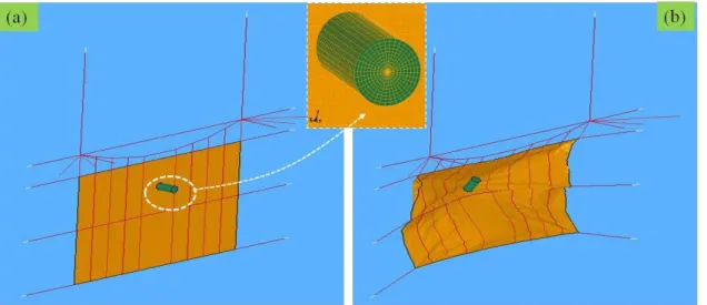
Fig. 7.FE model of the R-LPR.(a): undeformed state.(b): a deformed state.
The intensity of dead load (weight per unit horizontal length):
ω0=
W
L (5)
This gives a value of 0.56 kN m−1.
Vertical component of cable tension due to the dead load:
V=ω0×L
2 (6)
And, the horizontal component:
H=ω0×L
8×s
2
(7) Thus, the resultant tension is given by:
T=pV2+H2 (8) which computes the value of pretension in the sag-cable to be approximately 11 kN.
The appropriately meshed and fully calibrated FE model was then to be impacted with the cylinder (rockfall equiva-lent block) of 1-ton mass, length to diameter ratio of 2, with an initial (incident) velocity of 17.33 m s−1 (kinetic energy of 150 kJ) at the location shown by the circle on the net area; following exactly what existed in the corresponding FM test situation. The block was modelled by Solid elements and assigned with the Rigid (MAT 020) material model. The re-inforced concrete used to mould the block in the test was as-sumed to have the density of 2600 kg m−3with an arbitrary Young’s modulus of 35 GPa and Poisson’s ratio of 0.167. The impact-contact algorithm Surface To Surface inbuilt in LS-DYNA was used with block and net, respectively, as master and slave parts, and constant values of coefficients of friction equalling to 0.15. The hourglass control (*HOURGLASS)
was introduced in stiffness form (IHQ=4). Finally, the LS-DYNA inbuilt explicit time history analysis was carried out to simulate the dynamic and nonlinear responses of the R-LPR.
3.4 Numerical results
Figure 7 shows the FE model of R-LPR, both in the unde-formed and deunde-formed states. This model has 73 894 nodes and 75 906 elements in total, with 60 000 Shells, 2946 Beams and 12 960 Solids and the the average computation time of the model in an ordinary PC workstation is around a day. The dense meshing for Solid was adopted to take precaution for possible instability due to contact penetration following the suggestion by Hallquist (2006). This is fair because as the stresses and strains for Rigid material assigned to the Solids are not updated in the time history analysis and, hence, the densely meshed elements require no further computational costs. The structural responses corresponding to those mea-sured in the FM, viz., the maximum cable tension, at loca-tion M, the corresponding maximum UFD slip-displacement (slippage), and the maximum out-of-plane displacement of wire-net (Dm), just below the impact point, are shown in Fig. 8. The authors’ sensitivity analyses (not detailed here for brevity) reveal the negligible effects of the parameters such as damping, hourglass, friction, etc. The overall results are in good agreement with the corresponding responses in the FM. Thus, it is assumed that the exercised NM is success-fully and completely simulating the behaviour of the resilient cable-net-dissipator structural system of the R-LPR.
4 Analytical modelling (AM)
‟
Fig. 8. Numerical simulation (NM) results. (a): maximum cable-tension, at location M. (b) Maximum UFD-slippage (slip-displacement), at location M.(c)Maximum wire-net’s out-of-plane displacement, just below the impact point. See also Fig. 3 for the corresponding FM results.
on rockfall protection, precisely the flexible (cable-net) pro-tective systems. Over a decade or so, numerical modelling has also proved its importance either to aid or replace the full-scale tests, which normally incurs a large budget and mechanically less detailed and, therefore, sometimes limited to fully disclose the behaviour of the structure. The con-cept, approach and application of simple, analytical mod-elling are rare, except for a few recent contributions such as Schellenberg (2007), Cantarelli et al. (2008) and Miranda et al. (2010). As the first attempt, in the present work, the authors have preferred to propose the simplest possible an-alytical model that may equivalently simulate the global re-sponse, primarily the displacement response. It has already been identified that the displacement may be the most vital performance criteria for LPR under the assumption that the barrier components do not fail, and the typical practical situ-ation to put the global displacement demand of the structure into priority has already been explained in Sect. 2.2.
Fig. 9.Analytical modelling and formulation.(a): a simple lumped mass SDOF analytical model proposed for LPR structure. (b): the formulated linear relation between the structural displacement and the velocity of the block; the slope of the line is also shown.(c): the nonlinear (quadratic) relation between the structural displacement and the incident kinetic energy of the block.
4.1 Model formulation
The structure was assumed to be modelled by a lumped-mass, equivalently linearly elastic, single-degree-of-freedom (SDOF) system. And, the model’s behaviour was assumed to be guided by the simple, first principles, of the conser-vation of linear momentum and the conserconser-vation of energy (Lam et al., 2010). The proposed model is shown in Fig. 9a. The equivalent lumped massMand the equivalent stiffness
S. Dhakal et al.: Modelling a newly developed rockfall protective cable-net structure 3207
m×V0=(m+M)×V⇒V=
m m+M×V0
or, V= V0
1+r withr= M
m (9)
Ek =
1 2m×V
2 0 =
1
2(m+M)×V 2
+δE
and,1
2(m+M)×V 2
=1 2K×1
2 (10)
Combining Eqs. (9) and (10), a displacement prediction equation is obtained as:
1=
r m
(1+r)K×V0⇒1∝V0(∝to mean proportional) (11)
or,
1= s
2Ek
(1+r)K⇒1∝ p
Ek,Ek∝12 (12)
Equation (9) represents the conservation of linear momen-tum, while Eq. (11) the conservation of energy, whereV0is the incident velocity, andEk the corresponding kinetic
en-ergy of the impacting block. V is the velocity of the coa-lesced block-structure system immediately after the impact and δE is the energy lost on impact. Clearly seen from Eqs. (11) and (12) is that the displacement is a linear func-tion of the incident velocity of the impacting block and is a quadratic function with the corresponding energy which is shown schematically in Fig. 9b and c. Importantly, the slope (gradient) of the linear displacement-velocity line is given by:
Slope=
r m
(1+r)K (13)
4.2 Model calibration
The straight forward calculations of the equivalent mass and the equivalent stiffness of the complex system like LPR are virtually impossible. Thus, they should be determined by back calculation by either of the earlier modelling, that is, the FM or the NM. Now, there is already a verified numerical model, so it may be readily utilised. Equations (9) and (13) of the analytical formulation may be used to determine the properties of the proposed model. For the latter, at least three numbers of numerical parametric analyses were deemed nec-essary. Here, a different idealized block was used. In fact, the analyses could have been continued with the same cylindri-cal block used in the FM or the NM. However, it was utilised up to numerically simulating the R-LPR as observed in the FM and to verify the NM adopted by the authors. For the subsequent parametric analyses of the R-LPR, a more ratio-nal rockfall looking ETAG027-like octagoratio-nal shape (EOTA, 2008; Peila and Ronco, 2009) was used. The decision was
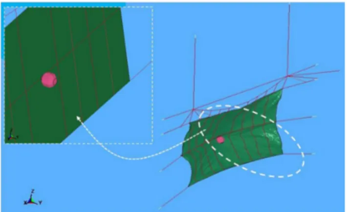
Fig. 10.The verified FE model of the R-LPR now impacted by the ETAG027-like block.
also dictated by the increasing global acceptance of the Eu-ropean codes. Figure 10 shows the deformed FE model of the structure impacted by the ETAG027-like octagonal block. It is again reminded that deformation (displacement response) is more important than the sufficiently safer force (stress states) for the performance of a typical LPR design, having identified from full-scale modelling.
Figure 11 represents a typical “Global Y-velocity” re-sponse time history of the cylindrical block of 1-ton mass impacting the studied R-LPR at the incident velocity of 17.33 m s−1. From this figure, the velocity immediately af-ter the impact, when the cable-net restraining system and the block move together (inelastic impact), is obtained to be 7.66 m s−1. Substituting the two velocity values in Eq. (9) gives the equivalent massM to be 1262 kg. Thus, one im-portant parameter is determined.
Figure 12, on the other hand, shows the plot of displace-ment response values at different velocities and impact ener-gies of the ETAG027-like octagonal block having the mass of 778 kg, confirmed after modelling, hitting the same verified numerical model. For the sake of effective graphical pre-sentation, with the two related curves on the same chart, the response displacement was deliberately placed on the hori-zontal axis despite that it is a dependent variable. Likewise, the slope defined by the expression in Eq. (13) was made equal to the inverse of the value calculated from the velocity-displacement plot of Fig. 12. The corresponding slope (dis-placement vs. velocity) comes out to be 68.45×10⁻³. Sub-stituting this value into the expression of slope, Eq. (13), with
Fig. 11.A typical time history response of the Global Y-velocity – including initial coalesced motion – of the cylindrical block of 1 ton mass and the incident velocity of 17.33 m s−1.
SDOF modelling to represent the highly complex system of LPR is not sufficient and needs modification. The neces-sary modification may be attributed to the factors such as geometric nonlinearity, dynamic loading, higher mode defor-mations, etc. Nonetheless, the simple analytical model may be readily retained as the basic variable constituting com-ponent of the correlation. The global displacement of the structure is, thus, conveniently predicted after a modification that compares with Eq. (14). The final form of the displace-ment prediction correlation for the studied LPR configuration modelled with the described very simple SDOF modelling is, therefore, as given in Eq. (15). A more general form of the correlation is shown in Eq. (16).
Dm=0.06845V0+2.135 (14)
1=√ mV0
63 366(m+1262)+2.135 (15)
1= s
m
1+Mm
KV0+2.135 (16)
Therefore, via back-calculations using the verified numer-ical modelling (second tier), the calibration and necessary modification over the simple analytical formulation, capa-ble of predicting the global displacement response of the complex structure could be successfully accomplished in the third-tier modelling. The correlation is the function of the structure’s equivalent global mass and equivalent global stiff-ness, and the rock-block’s mass and velocity. Application of the proposed correlation, for example, to a block of mass of 1000 kg impacting at the velocity of 17.33 m s−1(as equiv-alent to the case of the cylindrical block described in the numerical modelling section), predicts the displacement re-sponse to be 3.58 m. This indeed compares very well with that obtained directly from the corresponding rigorous nu-merical simulation. However, it may be noted that the corre-lation, having devised by considering a limited range of im-pact energy basically by varying the velocity of imim-pact, may not be extrapolated to either much lower or much higher en-ergy (say, roughly as high as 500 kJ) since other factors such
Fig. 12. Displacement response of R-LPR at various incident ve-locities and the corresponding kinetic energies of the impacting block by using the model shown in Fig. 10. The slope to be de-termined is marked by a circle.
as the localized contact-impact effects may potentially intro-duce nonlinear functions.
4.3 Further application of the model
The lumped-mass SDOF equivalent structural model is very convenient to handle and visualize, again to be emphasized, for the global structural displacement performance (physi-cally corresponding with the out-of-plane displacement of the real LPR). Having known the equivalent mass and the equivalent stiffness, one may utilise the model for various individual aspects. For example, if someone is interested in having the insight into the structure through its natural frequency or period of vibration, it may be computed from Eq. (17) given below.
Tn=2π r
M
K (17)
Or, in coalesced vibration,
Tn=2π r
m+M
K (18)
Equation (18), for instance, with the block of mass of 1 ton, for instance, gives a value equal to 1.19 s.
S. Dhakal et al.: Modelling a newly developed rockfall protective cable-net structure 3209 the various parameters such as the varying impact energy or
velocity of the block or the ratio of the mass of the LPR struc-ture to that of the impacting block at the constant impact en-ergy – the trend “not captured by the contemporary codified calculation methods for impact actions” (Yang et al., 2011), the simple correlation derived in Eq. (16) may help. Clearly seen is that the wire-net displacement may be reduced by simply increasing the mass of its cable-net resilient system (density, for instance), not necessarily the stiffness contribut-ing properties such as the thickness. Again, with this simple model, the different displacement responses of an LPR for “heavy” (larger mass, smaller velocity) and “light” (smaller mass, larger velocity) falling rock-boulders that might have carried the same kinetic energy may be clearly understood. A detailed exploration on the characterisation of rockfall im-pact loading onto the structure may be found in a separate companion contribution by the authors in future.
5 Conclusions and recommendations
Commenced with a brief reporting of the development of a new configuration of rockfall protective cable-net structure (flexible barrier) in Japan, known as Long-span Pocket-type Rock-net (LPR), the paper focussed on the authors’ primary objective of conducting a three-tier modelling of the newly developed protective system. Their methodologies and re-sults were presented separately and briefly. A 15-m span structure with designated design impact energy resistant ca-pacity of 150 kJ was taken as the reference case (R-LPR) throughout the study.
For the time being, the LPRs of span from 10 m to 30 m are proposed for low-to-medium impact energy scenarios (say below 500 kJ of design impact energy resistant capacity), at the toe of hill or nearby the infrastructure to be protected, or more precisely when there is a limited space between the road carriageway and the hill-slope. In Japan, before the in-troduction of LPR, either short-span (3 or 5 m) pocket-type rock-net or rock-sheds (reinforced concrete galleries) were prevalent in the described sites. The former not only had lower capacity (thereby requiring installation in cascade up-hill) and incurred larger cost for more materials as well as installation, but also performed weakly by having their posts repeatedly damaged by the direct impact of the falling rock-boulder. The latter was not only difficult to construct and had very high dead-load, but was again an expensive alterna-tive, especially because they have high-to-very-high capacity range which is never utilised in the low-to-medium rockfall hazard sites. With the advent of LPR system, the disadvan-tages of the prevailing solutions have been overcome and in either case, it has ecological benefits as well. The system was first introduced in real field at various locations of Kurei-Suzaki Line road, along Pacific Ocean, in Kochi Prefecture of Japan, and the subsequent performance has been found encouraging. These structures are now finding an increased
application within Japan and similar systems are expected to be developed in future in other parts of the world too. In fact, assuming the construction materials are fairly avail-able, rockfall protective earthen embankments (or geo-cells) widely developed, tested and used in various parts of the world can be as effective and economic as flexible barriers even in the low-to-medium rockfall hazard sites. However, they generally require a larger space, and the design like LPR can be a good alternative in such a constraint.
In the first-tier modelling of the considered R-LPR struc-ture, full-scale (experimental) modelling was discussed. The structure performed pretty well in the test. Owing to the sufficiently safer stress state in cable too, the displacement-based performance criteria may be emphasized in the anal-ysis and design of an LPR structure, due to the fact that the targeted sites of LPR application generally have very lim-ited set-back. Thus, the authors tend to recommend that an extended investigation be made in future on the various pos-sibilities to control the out-of-plane displacement of wire-net in LPR but still limiting the stresses even if higher strength steel is not utilised for cables. One of the solutions may be increasing the weight of the structure as suggested by the simple analytical formulation explained in the later section of this work (Sect. 4.3). Moreover, it is identified that the evaluation, enhancement and optimization of the existing U-bolt-type Friction-brake energy dissipating Devices (UFDs) integrated into an LPR system is worth trying in future. How-ever, for such various intended explorations that shall be re-quiring a number of parametric analyses of the structure, the method of full-scale modelling is not viable and may not be sufficient as well due to their limitations in instrumentation. This justifies the need of searching for more easily replica-ble, as simplified and convenient as practicable and overall, the object-oriented and cheapest alternative.
In the second-tier modelling, the R-LPR structure was modelled with Finite Elements in the available numerical tool of LS-DYNA. A simplified modelling was adopted, wherein the main impact resilient cable-net-dissipator sys-tem was kept in the limelight but again following an equiv-alent modelling concept for the wire-net and the dissipator. The former was modelled by the Shell and the latter by the Truss elements. Their constitutive properties were modelled and calibrated by appropriate experiments conducted during the past full-scale test verification and/or demonstration cam-paign leading to the development of the LPR system. The de-veloped numerical model excellently simulated the full-scale modelling results.
the first principles of the conservation of linear momentum and energy. The equivalent properties of the model were determined by back-calculations of the results of analyses on the verified numerical model, which also suggested the modification in the basic form of the displacement equation – thereby enabling the prediction of the complex nonlinear and dynamic displacement response of the R-LPR-like struc-ture. Being aware of the much developed and internation-ally accepted European guidelines for rockfall protection, the EOTA (2008) recommended block shape was modelled for the subsequent parametric analyses. The proposed analytical model, despite being the simplest of its kind, which could be developed for a selected set of designs based on experimental and/or numerical simulations, can be very helpful to a design engineer to conduct various simple computational paramet-ric analyses for the better understanding of the behaviour of the system. The model, for instance, may be utilised for the investigation toward enhancing the effectiveness of an LPR structure by controlling its global displacement response, or even for the preliminary design works in a practical range of designated impact energy – neither going too high nor too low. The detailed application of the proposed numeri-cal and analytinumeri-cal modelling (displacement predictive corre-lation) shall be covered in a separate companion paper.
In a nutshell, the authors successfully materialized the set objective of three-tier modelling of a newly developed rock-fall protective system. The approach and rationale of the modelling contained in this work may be useful also while dealing with other similar development and/or analyses of a protective system in future. It is, however, to be highlighted here that if such a protective system is developed in Europe, for the barrier to be executed in the field, the existing practice would require to pass the full-scale test certification based on the guideline ETAG027 recently endorsed by EOTA fol-lowing the existing Swiss guideline endorsed by SAEFL and WSL (Gerber, 2001). Even in such situations, the proposed simplified numerical and analytical modelling would become very helpful for conducting parametric analyses for prelimi-nary design, system enhancement and optimization before fi-nally entering into full-scale modelling for test-certification.
Acknowledgements. The authors thank Daiichi Consultants Co.,
Kochi, Japan (particularly the chairperson, T. Ushiro), Nihon Protect Co., Matsuyama, Japan and Besafe Consultants Co., Niigata, Japan for the test results used in this paper. The first author gratefully acknowledges N. T. K. Lam, University of Melbourne, Australia, A. Volkwein, WSL, Switzerland, and J. P. Ghimire, Commonwealth Engineers Co. Ltd., Tokyo for their kind email responses, comments and helpful suggestions at times. Sincere thanks are also due to two anonymous referees who very minutely and beautifully commented over the submitted manuscript, thereby helping to improve it to the present stage. Last but not least, the first author is thankful to his wife Sweta Acharya (Dhakal) for her assistance throughout.
Edited by: T. Glade
Reviewed by: two anonymous referees
References
Arndt, B., Ortiz, T., and Turner, K.: Colorado’s full-scale field test-ing of rockfall attenuator systems, Transportation Research Cir-cular E-C141, Transportation Research Board, 2009.
Azzoni A., Barbera, G. L., and Zaninetti, A.: Analysis and predic-tion of rockfalls using a mathematical model, Int. J. Rock Mech. Min. Sci. Geomech. Abstr., 32, 709–724, 1995.
Badger, T. C., Duffy, J. D., Sassudelli, F., Ingraham, P. C., Perreault, P., Muhunthan, B., Radhakrishnan, H., Bursi, O. S., Molinari, M., and Castelli, E.: Hybrid barrier systems for rockfall pro-tection, in: Proc. of the Interdisciplinary Workshop on Rockfall Protection, edited by: Volkwein, A., Morschach, Switzerland, 10–12, 2008.
Badger, T. C., Dobrev, B., Anderson, M., Radhakrishnan, H., and Muhunthan, B.: Structural design of a hybrid drapery system, in: Book of abstract, Interdisciplinary Workshop on Rockfall Pro-tection, edited by: Molk, M., Melzner, S., Sausgruber, T., and Tartarotti, T., 3 pp., 2011.
Bertolo, P., Oggeri, C., and Peila, D.: Full-scale testing of draped mesh for rock fall protection, Can. Geotech. J., 46, 306–317, 2009.
Besafe: E-fence experimental report, Besafe Co. Ltd., Niigata, Japan, 2006 (in Japanese).
Boetticher, A. V., Glover, J., Volkwein, A., and Denk, M.: Mod-elling flexible wire netting applied to rock fall attenuating sys-tems, in: Book of abstract, Interdisciplinary Workshop on Rock-fall Protection, edited by: Molk, M., Melzner, S., Sausgruber, T., and Tartarotti, T., 71–72, 2011.
Bunce, C. M., Crude, D. M., and Morgenstern, N. R.: Assessment of the hazard from rockfall on a highway, Can. Geotech. J., 34, 344–356, 1997.
Cantarelli, G., Giani, G. P., Gottardi, G., and Govoni, L.: Modelling rockfall protection fences, Web Proc. Of First World Landslide Forum, Tokyo, Japan, 662–667, 2008.
Castro-Fresno, D., Diaz J. J. d. C., Lopez, L. A., and Nieto, P. J. G.: Evaluation of the resistant capacity of cable nets using the finite element method and experimental validation, Eng. Geol., 100, 1–10, 2008.
Cazzani, A., Mongiovi, L., and Frenez, T.: Dynamic finite element analysis of interceptive devices for falling rocks, Int. J. Rock Mech., 39, 303–321, 2002.
Crosta, G. B. and Agliardi, F.: A methodology for physically based rockfall hazard assessment, Nat. Hazards Earth Syst. Sci., 3, 407–422, doi:10.5194/nhess-3-407-2003, 2003.
Descoeudres, F., Stoffel, S. M., Boll, A., Gerber, W., and Labiouse, V.: Chapter 4, Rockfalls, in: Coping study on disaster resilient infrastructure, commissioned by the secretariat for the interna-tional decade for natural disaster reduction for the INDR pro-gramme forum “Parterships for a safer world in the 21st century”, edited by: Minor, H.-E., United Nations, 37–46, 1999.
Dhakal, S., Bhandary, N. P., Yatabe, R., and Kinoshita, N.: Finite el-ement modelling and parametric analyses of a Long-span Pocket-type rockfall interceptive cable-net structure, Proc. of Second World Landslide Forum, Rome, Italy, 3–7 Oct., 2011a.
S. Dhakal et al.: Modelling a newly developed rockfall protective cable-net structure 3211
2011b.
Dhakal, S., Bhandary, N. P., Yatabe, R., Pradhan, P. L., and Tiwari, R. C.: Finite element modeling and decoupled seismic stability analysis of a zoned rockfill dam designed by traditional empirical methods, J. Inst. Eng., 8, 71–92, 2011c.
Dorren, L. K. A. and Berger, F.: Stem breakage of trees and en-ergy dissipation during rockfall impact, Tree Physiol., 26, 63–71, 2005.
Eliassen, T. D.: Evaluation of hybrid rockfall barrier/drape system, Initial Report-Experimental Features, Project No. 2011-1, Work Plan 2008-1, Ste of Vermont, Agency of Transportation, Materi-als and Research Section, 9 pp., 2011.
EOTA: Guideline for European Technical Approval of falling rock protection kits, European Organization for Technical Approvals, Brussels, 53 pp., 2008.
Evans, S. G. and Hungr, O.: The assessment of rockfall hazard at the base of talus slopes, Can. Geotech. J., 30, 620–636, 1993. Fukazawa, J., Sonoda, Y., and Tamai, H.: A fundamental study on
the discretization degree and calculation accuracy of impact anal-ysis using SPH method, J. Struct. Eng., 56A, 1169-1176, 2010 (in Japanese).
Fell, R., Corominas, J., Bonnard, C., Cascini, L., Leroi, E., and Savage, W. Z. on behalf of the JTC-1 Joint Technical Committee on Landslides and Engineered Slopes: Guidelines for landslide susceptibility, hazard and risk zoning for land-use planning, Eng. Geol., 102, 85–98, 2008a.
Fell, R., Corominas, J., Bonnard, C., Cascini, L., Leroi, E., and Sav-age, W. Z. on behalf of the JTC-1 Joint Technical Committee on Landslides and Engineered Slopes: Guidelines for landslide sus-ceptibility, hazard and risk zoning for land-use planning, (Com-mentary), Eng. Geol., 102, 99–111, 2008b.
Gerber, W.: Guideline for the approval of rockfall protection kits, Swiss Agency for the Environment, Forests and Landscape (SAEFL), and Swiss Federal Research Institute (WSL), Berne, Switzerland, 41 pp., 2001 (Amendment, 2006).
Giani, G. P.: Rock slope stability analysis, Balkema, Rotterdam, Netherlands, 1992.
Giani, G. P., Giacomini, A., Migliazza, M., and Segalini, A.: Exper-imental and theoretical studies to improve rock fall analysis and protection work design, Rock Mech. Rock Engng., 37, 369–389, 2004.
Grassl, H., Volkwein A., Anderheggen, E., and Ammann, W. J.: Steel-net rockfall protection, Proc. of Seventh International Conference on Structures under Shock and Impact, Montreal, Canada, 143–153, 2002.
Guzzeti, F., Crosta G., Detti, R., and Agliardi, F.: STONE: a com-puter programme for the three dimensional simulation of rock-falls, Comput. Geosci., 28, 1079–1093, 2002.
Guzzetti, F., Reichenbach, P., and Wieczorek, G. F.: Rockfall haz-ard and risk assessment in the Yosemite Valley, California, USA, Nat. Hazards Earth Syst. Sci., 3, 491–503, doi:10.5194/nhess-3-491-2003, 2003.
Gottardi, G. and Govoni, L.: Full-scale modelling of falling rock protection barriers, Rock Mech. Rock Eng., 43, 261–274, 2010. Hallquist, J. O.: LS-DYNA theory manual, Livermore Software
Technology Corporation (LSTC), 2006.
Japan Road Association: Rockfall Mitigation Handbook, Maruzen, 2000 (in Japanese).
Kinoshita, N.: Development of Long-span Pocket-type Rock-net,
Proc. of Annual Meeting of Ministry of Land, Infrastructure, Transport and Tourism, Shikoku Regional Development Bureau, Japan, I1, 1–4, 2009.
Lam, N. T. K., Tsang, H. H., and Gad, E. F.: Simulations of re-sponse to low velocity impact by spreadsheet, Int. J. Struct. Stab. Dynam., 10, 1–17, 2010.
LSTC: LS-DYNA Keyword User’s Manual, Vol. I-II, V971, Liver-more Software Technology Corporation (LSTC), 2007. Maegawa, K.: Weight impact tests on a flexible polyethylene net
rock fence, Proc. of the 3rd International Conference on Protec-tion of Structures against Hazards, 43–50, 2006.
Masuya, H., Amanuma, K., Nishikawa, Y., and Tsuji, T.: Basic rockfall simulation with consideration of vegetation and appli-cation to protection measure, Nat. Hazards Earth Syst. Sci., 9, 1835–1843, doi:10.5194/nhess-9-1835-2009, 2009.
Miranda, S. d., Gentilini C., Gottardi, G., Govoni, L., and Ubertini, F.: A simple model to simulate the full-scale behaviour of falling rock protection barriers, in: Physical Modelling in Geotechnics, edited by: Springman, S. M., Laue, J., and Seward, L. J., London, 1247–1252, 2010.
Muhunthan, B., Shu, S., Sasiharan, N., Hattamleh, O. A., Badger, T. C., Lowell, S., M., and Duffy, J. D.: Analysis and design of wire mesh/cable net slope protection, Final Research Report. Wash-ington State Transportation Commission – Department of Trans-portation, US Department of Transportation – Federal Highway Administration, 2005.
Muraishi, H., Samizo, M., and Sugiyama, T.: Development of a flexible low-energy rockfall protective fence, QR of RTRI, 46, 161–166, 2005.
Nicot, F., Cambou, B., and Mazzoleni, G.: Design of rockfall re-straining nets from a discrete element modelling, Rock Mech. Rock. Eng., 34, 98–118, 2001.
Peila, D.: Chapter 12, Ground reinforced embankments for rock-fall protection – From real scale tests to numerical modelling, in: Rockfall Engineering, edited by: Lambert, S. and Nicot, F., John Wiley & Sons, New York, ISTE Ltd., London, ISBN 978-1-84821-256-5, 2011.
Peila, D. and Guardini, C.: Use of the event tree to assess the risk re-duction obtained from rockfall protection devices, Nat. Hazards Earth Syst. Sci., 8, 1441–1450, doi:10.5194/nhess-8-1441-2008, 2008.
Peila, D. and Ronco, C.: Technical Note: Design of rockfall net fences and the new ETAG 027 European guideline, Nat. Hazards Earth Syst. Sci., 9, 1291–1298, doi:10.5194/nhess-9-1291-2009, 2009.
Peila, D., Pelizza, S., and Sassudelli, F.: Evaluation of behaviour of rockfall restraining nets by full scale tests, Rock Mech. Rock Eng., 31, 1–24, 1998.
Reddy, J. N.: An introduction to nonlinear finite element analysis, Oxford University Press, New York, 2004.
Sasiharan, N., Muhunthan, B., Badger, T. C., Shu, S., and Carra-dine, D. M.: Numerical analysis of the performance of wire mesh and cable net rockfall protection systems, Eng. Geol., 88, 121– 132, 2006.
Schellenberg, K.: On the design of rockfall protection galleries, PhD Thesis, Institute of Structural Engineering, Swiss Federal Institute of Technology, Zurich, Switzerland, 2007.
Depart-ment of Transportation, Office of Transportation, Materials and Research, Sacramento, CA, USA, 1990.
Tajima, T., Maegawa, K., Iwasaki, M., Shinohara, K., and Kawakami, K.: Evaluation of pocket-type rock net by full-scale tests, Proc. of 33rd IABSE Symposium, Bangkok, Thailand, available at: http://133.28.114.77/maegawa/ IABSE-Symposium2009-212 07 01.pdf, 8 pp., 2009.
Ushiro, T., Masahiro, K., Shinohara, S., and Kinoshita, K.: An experimental study related to rock fall movement mechanism, Doboku Gakkai Ronbunshu F, 62, 377–386, 2006 (in Japanese). Vogel, T., Labiouse, V., and Masuya, H.: Rockfall protection as an
integral task, Struct. Eng. Int., 19, 304–312, 2009.
Volkwein, A.: Numerical simulation of flexible rockfall protec-tion systems, Diss. ETH, Nr. 15641, PhD thesis, ETH, Zurich, available at: http://e-collection.library.ethz.ch/eserv/eth:27491/ eth-27491-02.pdf, 134 pp., 2004 (in German).
Volkwein, A.: Numerical simulation of flexible rockfall pro-tection systems. Proc. of The ASCE International Confer-ence on Computing in Civil Engineering, Cancun, Mexico, doi:10.1061/40794(179)122, 2005.
Volkwein, A., Roth, A., Gerber, W., and Vogel, A.: Flexible rockfall barriers subjected to extreme loads, Struct. Eng. Int., 19, 327– 332, 2009.
Yang, Y., Lam, N. T. K., and Zhang, L.: Evaluation of simplified methods of estimating beam responses to impact, Int. J. Struct. Stab. Dynam., accepted, 2011.