Pattern operators for grid environments
Maria Cec´ılia Gomes
a, Omer F. Rana
band Jos´e C. Cunha
aaDepartamento de Inform ´atica, Universidade Nova de Lisboa, Portugal
bDepartment of Computer Science, Cardiff University, UK
Abstract. A pattern based approach for developing applications in a Grid computing environment is presented, and is based on
the ability to manage components and their interactions. The approach provides a formal way of combining recurrent themes in Grid applications, and provides a set of operators that may be used to manipulate the patterns. The operators may be applied to individual patterns or groups, and may be managed as an independent library. The patterns distinguish between service providers and users, and may be used to also analyse the properties of a collection of components, or to vary these properties subject to a set of predefined constraints. Patterns are expressed in the Unified Modelling Language (UML), and operators correspond to manipulation of components within each pattern.
1. Introduction and related work
Component based software development provides an effective way to develop applications from a range of different software libraries, and wrapped legacy codes. Components can vary in complexity and granularity – ranging from complete applications to specialised sub-routines. A number of projects (see a list in [1,15]) have explored component composition and workflow man-agement for components in the context of Grid comput-ing [14,16]. Generally, these environments involve a user interface which enables components to be selected from a repository, and combined using an editor. The interfaces to the components are generally pre-defined, and often expressed in XML – and these environments are generally called “Problem Solving Environments” (PSEs) [17]. Such environments generally consist of 3 tiers: i) a user portal to enable interaction with the components, (ii) a series of middle tier services – such as a data management service, one or more compute services, etc, and (iii) the physical resources on which the components are to be executed. Manipulating ei-ther individual components or groups of components is a useful extension – and little support is directly pro-vided in existing environments to achieve this. It is also useful to determine and abstract common interactions between components, and to make these abstractions available to a user. One novel theme addressed in this paper is the ability to view component composition (to
solve a particular problem) as being equivalent to ma-nipulating a structural pattern using pre-defined opera-tors. Subsequently, the resulting structure can be ma-nipulated via behavioural operators that enable multi-ple data flows to co-exist within a system. A user (ap-plication developer) may find useful structural or be-havioural patterns – in particular application contexts – and record these within a patterns library. These can then be configured using the operator library.
The approach presented here is primarily aimed at computational scientists and developers, who have some understanding of the computational needs of their application domain. A scientist should be aware about the likely co-ordination and interaction types between components of the application (such as a database or numeric solver etc). The structural and behavioural patterns presented here will enable such scientists and developers to utilise common usage scenarios within a domain (either the use of particular components, such as database systems, or interactions between compo-nents, such as the use of streaming).
The features distinguishing Grid environments from other distributed computing approaches include: het-erogeneity and dynamicity i.e. the infrastructure can change significantly over the lifetime of a single ap-plication, is composed of a range of different plat-forms, and may be managed by different administrators (see [21] for a useful survey). As there are likely to be a range of different users utilising a Grid infrastructure
with differing abilities – less experienced users may find it difficult to identify useful architectural models for interconnecting components. The existence of a pre-defined set of patterns is therefore particularly use-ful in this context. Additionally, once components have been connected together, another major difficulty is the need to identify suitable coordination mechanisms be-tween components. Providing a set of operators and common abstractions at the “behavioural” level is there-fore important. This work aims to extend Grid applica-tion development environments with structuring mech-anisms based on commonly recurring patterns. Using a library of design templates, a user is able to combine these with other specialised components that may be required in a particular application domain – both at design and execution times.
A number of approaches exist already for modelling interactions between components in the context of Grid environments, or for developing formal models of job submission and management in a Grid [29]. These, however, do not provide any support for enabling a user to subsequently utilise the outcome of these mod-els. Marinescu [3,4] provides a common abstraction for modelling workflow to support Web and Grid Ser-vices. The approach is centered on developing graph-ical abstractions that can be used to model interaction patterns between components. The graphical patterns model aspects such as AND/OR/XOR based interac-tions – and the focus is to support a workflow enactment engine that may be used to co-ordinate component ex-ecution. Similarly, a key emphasis in the Fraunhofer Resource Grid [2] is on developing a Grid Resource and Job definition language, to enable job submission, re-source selection, and allow a description of dependen-cies which exist between resources. In this work, the Grid Job Definition Language may be mapped to a se-ries of parameterised Petri Net (PN) blocks. Each block
represents some aspect of the language such asTask
execution and synchronisation,Conditionalsand
Choice, and loops (such as theWhile . . . doloop etc). Each PN block is encoded in XML based on the Petri Net Markup Language (PNML) [28]. Both of these approaches are focused on providing either a spe-cialised representation scheme, or a workflow manage-ment approach for components and/or services. Our approach is more generic, and based on the provision of a standard pattern library in UML, and associated operators. Some of these operators may be used to sup-port workflow, and PN models for patterns may also be constructed from their UML descriptions, as outlined in [6]. The PN models are useful to capture the
seman-tics of the operators, and to undertake what-if inves-tigations when combining operators. The availability of UML templates makes our approach more widely deployable, and may be used with a number of existing toolkits such as Rational Rose or TogetherJ (a survey can be found in [7]). The utilisation of languages such as Java (such as the CoG [12] interface to Globus) and emerging interest in Web Services [11] identifies the importance of using object-oriented design approaches. Various tools are currently available which can take UML diagrams and generate code fragments for these technologies. We therefore feel that a representation centered on UML is easier to translate into working designs.
Alternative related work has been undertaken by the parallel computing community, and is based on the use of algorithmic skeletons. The predominant motivation behind this has been the need to overcome the diffi-culty of constructing parallel programs – by capturing common algorithmic forms which may subsequently be used as components for building parallel programs [23, 24]. Such skeletons are expected to provide param-eterisable abstractions that may be composed – gen-erally using a functional programming language. A skeleton is expected to be transparent to an application user (and may come with a pre-packaged implementa-tion). Skeletons are viewed formally as polymorphic, higher-order functions – which may be repeatedly ap-plied to achieve various transformations (on data struc-tures such as lists). Herrmann and Lengauer [25] out-line the use of a programming language “Higher-order Divide and Conquer” (HDC) based on a subset of the functional programming language Haskell. They sug-gest that the use of a powerful type system in func-tional languages make them more suitable than other paradigms. Although useful for specifying programs in a concise syntax, we believe such approaches are limited in the context of Grid environments. This is primarily due to the absence of tools available in such languages for connecting to Grid middleware, such as Globus or UNICORE, although skeletons based ap-proaches do provide a useful prototyping tool for anal-ysis. Our use of “operators” (discussed in subsequent sections) borrows from the use of transformation tech-niques in skeleton based approaches, albeit our focus is on the use of object-oriented techniques. Further-more, our design patterns and operators are aimed at supporting workflow-based PSEs.
A Pattern encodes a commonly recurring theme in
service or component composition. It allows good
domains. A pattern is generally defined in an applica-tion independent manner, and used to encode particular useful behaviours. Patterns are particularly useful for configuring and specifying systems that are composed of independent sub-domains. Patterns are aimed at cap-turing some generic attributes of a system – which may be further refined (eventually) to lead to an implemen-tation. These are important requirements for Grid com-puting applications, which generally need to operate in dynamic environments. Providing patterns will ease the task of Grid application developers, who may de-ploy previously generated templates as an initial step, and then refine these based on our operators. The use of pattern operators is also particularly important to deal with dynamicity, because it provides a user the capabil-ity to modify a pattern at run time. Furthermore, pattern operators may be applied in an ordered combination – and may be shared between users. The presented struc-tural and behavioural operators may be implemented using a number of different scripting languages (such as Python or Perl) – and therefore the specified semantics are not restricted to our Java implementation.
The core of this work is the systematic identifica-tion of collecidentifica-tions of operators that can manage a set of useful patterns in Grid environments, via a PSE. A PSE provides a collection of tools necessary to sup-port problem description, and subsequently execution of the problem on computational resources. PSEs have ranged from those based on functional language based descriptions, to component-based composition tools. The component repository provides wrapped scientific codes or specialised components available within a given application domain – combined together using an editor, with access to a resource manager for execu-tion. Patterns can be provided in a repository – and can include generic patterns (as discussed in this paper), or those created by a user.
Section 2 introduces an application example where patterns and operators may be useful for configuring and reconfiguring a PSE. This example will be used throughout the paper. Section 3 describes Pattern
tem-plates starting with Structural pattern temtem-plates and
ending with Behavioural pattern templates. Section 4 describes the Structural and Behavioural Operators, and section 5 illustrates operator semantics. Section 6 describes implementation status. Finally, some conclu-sions are presented.
2. An application example
A PSE configuration example is provided to describe activities that are commonly required to manage an
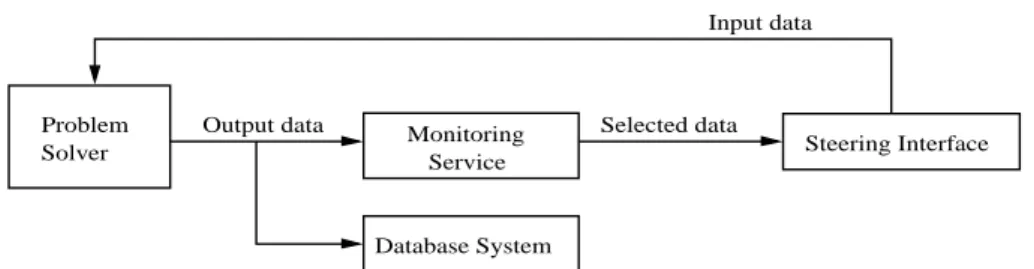
ap-plication. This example will be used throughout the pa-per for explaining the applicability of patterns and op-erators. Figure 1 shows an example of a PSE combin-ing different types of services, which appear frequently in Grid applications. The Problem Solver component represents a service running some scientific experiment that continuously produces data. An instance of such a service may be a wave generator or a matrix solver. Af-ter receiving some initial input parameAf-ters, the service starts producing data that can be analysed or stored for “post-mortem” analysis. The Problem Solver service may be steerable, meaning that its input parameters can be changed while the service is executing. By adjusting the input parameters a user may, for example, generate particular behaviours using this service.
Steering is frequently supported by two types of ser-vices: a Monitoring Service and a Steering interface. The Monitoring Service is used to register relevant out-put data or events produced by the Problem Solver. The data/events are filtered by the Monitoring Service and are passed to a Steering Interface that shows them to the user in a pre-defined format. Consequently, a user may use the Steering Interface to undertake “what if” scenarios – generally by defining new values for the Problem Solver’s input data. Furthermore, one may consider that several users have access to the Steer-ing Interface, thus requirSteer-ing some coordination over changing the parameters of the Problem Solver.
This type of application may also include another service, namely a Database System to store all the out-put produced by the Problem Solver. This enables a user to reconfigure the PSE using the stored data, with-out requiring the Problem Solver to be stopped. Alter-natively, a user may re-examine output data for addi-tional processing after the Problem Solver terminates its execution (based on pre-defined behaviour or as a result of a fault). These are illustrated in Figs 2 and 3: in Fig. 2 the Monitoring Service is stopped so that it can be replaced with a more complex tool like the
Monitor-ing and Statistics service in Fig. 3; in the meantime, the
Problem Solver continues its execution and its output is kept in the Database System. The alternative sce-nario is illustrated in Fig. 4: after the Problem Solver terminates its execution, its output can be processed, either from the beginning or from the point at which the Monitoring Service was being replaced (and that would otherwise be lost). In this case, the Database System acts as a temporary buffer.
The next section describes structural and behavioural pattern templates and identifies which patterns could be used to configure a PSE, as outlined in Fig. 1.
Sec-Steering Interface Service
Monitoring Selected data Output data
Input data
Database System Problem
Solver
Fig. 1. A PSE supporting the active steering of a Problem Solver. The arrows represent the flow of data.
Problem
Solver Service Steering Interface
Monitoring
Database System Output data
Fig. 2. The Monitoring service is stopped and consequently the Steering interface also stops. The output data is not lost because it is being saved in the Database system.
Problem
Solver Steering Interface
Monitoring and Statistics Service Selected data Output data Input data Database System
Fig. 3. The initial Monitoring service is replaced with a more complex one (Monitoring and Statistics service), which is activated to continue the filtering of the output data.
Database System Problem
Solver Steering Interface
Monitoring and Statistics Service
Selected data
Saved output data
Fig. 4. After the Problem Solver terminates its execution, data can be re-analysed.
tion 4 subsequently describes the application of struc-tural operators to build that PSE, and the application of behavioural operators to control the PSE’s execution.
3. Pattern templates
Patterns capture commonly occurring structural and behavioural aspects of components. Structural patterns encode component connectivity, and identify common
ways in which components may be combined within a given application domain (an example of this is the data flow pipeline used in rendering, which in-volves a data input, simulation/rendering, visualisation pipeline). Structural patterns may also contain a hi-erarchy, allowing the embedding of a pattern within another (these embedding are supported through spe-cialised operators). Structural pattern templates there-fore consist of component place holders, where each component is instantiated at run time.
Behavioural patterns encode useful required
func-tionality without necessarily identifying the particu-lar components involved. Components within a be-havioural pattern primarily identify interaction con-straints, and not the exact functionality required from each component. Behavioural patterns can therefore capture temporal or flow dependencies between com-ponents. Flow dependencies model data and control flows, and encode execution ordering on components (flow dependencies may be used to express synchro-nisation constraints, for instance). Behavioural pat-terns may be defined based on interactions between components (such as Peer-2-Peer or Client/Server), to schemes used to update the behaviour of each compo-nent.
Our approach is applied at four different levels. The lowest level provides Structural Patterns – which enable static composition of components into a data/control flow. Structural Patterns enable the description of com-monly recurring topological aspects of an application – but do not constrain the flows between these topological entities in any way. These Structural Patterns may be manipulated via Structural Operators – which enable a constrained way to modify the Structural Patterns. The constraints are defined by the semantics of the opera-tors – and relate to the result generated after the op-erator has been applied. Subsequently, flows on these Structural Patterns need to be specified – and this is achieved by identifying a Behavioural Pattern over the structure. Once again, the Behavioural Patterns may be configured statically or at run-time using Behavioural Operators. The division into these four stages of design is based on existing uses of application construction in PSEs. Based on our approach, a user must first commit to a structural pattern, and then to a behavioural one. Structural patterns therefore try to capture how many machines (for instance) or groups are necessary to exe-cute a given application – and do not instantiate these to particular instances until the Behavioural operators are applied. The four stage approach therefore reflects the approach adopted by application schedulers – but tries to abstract this as a collection of patterns and operators – and brings it closer to the application construction process.
To use these patterns and operators, a user launches a PSE visual editor to connect components together. This PSE tool (as identified in [17]) is augmented with a Pattern Template (PT) and Operator library. The user may select a PT from the library, and may apply one or a combination of operators to modify the structure of the template. The structural operators provide a
trans-formation between patterns, and are invariant to a given PT structure. The user can also modify the structure of a PT directly using the editor. The result may be stored by the user as a new template in a user-defined PT li-brary. Once the structure has been defined, the user now instantiates components to the elements of a PT. This is then followed by defining interactions between components – based on the provided Behavioural Pat-tern Templates. Subsequently, these interactions may be modified using the Behavioural Operators.
The rest of this section gives examples of structural and behavioural patterns, as well as which could be used to configure the example defined in section 2.
3.1. Structural pattern templates: Topological Topological patterns represent structural shapes that
frequently occur in Grid systems. For illustration pur-poses, we identify three basic shapes as possible can-didates within this category: star, pipeline, and ring.
The Star pattern is an aggregation of three compo-nents: the Nucleus is the center of the star; a Satellite represents the elements communicating with the star; and the SimpleChannel binds together a Satellite to the
Nucleus. The Nucleus may be connected to several
in-stances of SimpleChannel, but each SimpleChannel is only connected to a single Satellite. The Client/Server model, for example, is simply a specific behavioral pattern over the Star structural pattern.
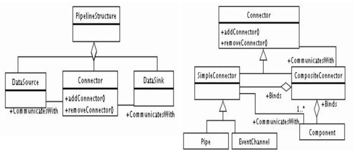
The Pipeline pattern is a sequence of stages which communicate with each other. The pattern occurs fre-quently in Grid applications. For example, a scientific application produces data to a sequence of filters (like
Data Analysis Tools), and the pipeline is terminated in a Visualisation Tool where the user can follow the
appli-cation’s execution. The pattern’s structure was adapted from the Pipes and Filters pattern [9].
The structure can be generally represented by three components (see left-hand side of Fig. 5): a
Data-Source produces data to a Connector, and the DataSink
consumes data from the Connector.
The Connector has a recursive structure, as illus-trated in the right-hand side of Fig. 5. A Connector may be a SimpleConnector (similar to a Unix pipe or an event channel) or it may be a CompositeConnector. The latter is a connected association of a
SimpleCon-nector and a Component. Recursively, the Compos-iteConnector is connected to another Connector (and
terminates at the SimpleConnector).
The Ring pattern represents, like the pipeline, a se-quence of stages, with no “first” or “last” stage. The
Fig. 5. The Pipeline and the Connector patterns.
structure of the Ring pattern is also based on the
Con-nector structural definition.
The difference is that a Component is always con-nected to two SimpleConnectors (in the simplest case, the unique component will have two connections to a single SimpleConnector). In Grid environments, the ring topological structure can be found in a number of applications, both in the context of application ex-ecution (such as for modelling interactions within a local area network) to logical topologies such as sup-porting an authentication chain when approving par-ticipants with multiple Certificate server. Each server delegates an authentication request to the next domain, and the last server replies to the original client. This chain based mechanism can also be found in resolving the address/location of an executable using a directory lookup service (as found in the Globus MDS [10]).
3.2. Structural pattern templates: Non-topological
The Adapter, Facade, and Proxy design patterns (adapted from [8]) are examples of non-topological structural patterns, which are particularly useful in the context of Grid computing.
The Adapter pattern allows communication between two elements when they do not have the same interface. In the Grid environment, the Adapter pattern has appli-cability, for example, in the adaptation of services, or as wrappers for legacy codes (such as Fortran binaries). If the client is expecting a different interface from the one provided by the server, the adapter can act as a translator. This pattern is also particularly useful for providing a mapping between the interface of an exist-ing code and a pre-defined component data model for Grids, such as CCA [26].
The Facade pattern (Fig. 6) is used when a sys-tem may be divided into several sub-syssys-tems, and the communication/entry-point into the system needs to be restricted. The Facade pattern is present in the struc-turing of the Grid in “domains”. The access to each domain (sub-system) in the Grid may be via a Facade interface.
The Proxy pattern is frequent in distributed systems. The access to Grid services, for example, is usually through a proxy (or gatekeeper). The structure of the pattern consists of an abstract interface (the Subject) representing the service, the implementation of the ser-vice (RealSubject), and a surrogate (Proxy) which for-wards the request to the implementor of the service.
3.3. Structural patterns in use
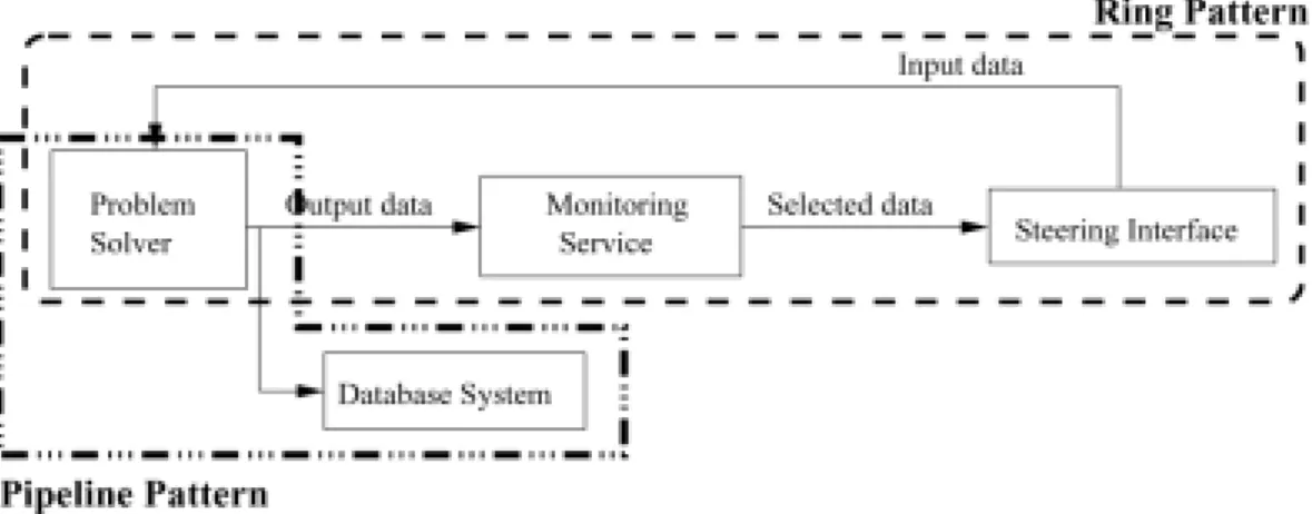
The PSE example from Fig. 1 can be configured based on some of the structural patterns described in the previous sections. As shown in Fig. 7, it is pos-sible to identify a ring pattern connecting the Problem Solver, the Monitoring Service and the Steering Inter-face. There is also a pipeline pattern connecting the Problem Solver and the Database System. To represent such a PSE, the user would define a ring template with three elements, and a pipeline template with two ele-ments. One way to combine the two patterns would be to embed the pipeline into one of the ring’s elements forming an hierarchy.
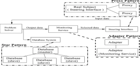
Figure 8 identifies three more structural patterns, namely for configuring individual services. For exam-ple, the star pattern may represent the Database Sys-tem considering that the sysSys-tem is composed of a set of distributed Database sub-systems. These sub-systems
subsystem classes Facade +discover() +execute() Domain1 +d1.discover() +d1.execute() Domain2 +d2.discover() +d2.execute() Subdomain2.1 +d2.d1.discover() +d2.d1.execute()
+Invokes +Invokes+Invokes
+Invokes
Fig. 6. The Facade design pattern. Example: the “Facade” provides a unified interface for accessing domains in the Grid environment, redirecting the calls to services like “discover” and “execute”.
Fig. 7. Identification of the Ring and Pipeline patterns in the PSE example.
are the Satellites in the ring’s structure, and they are controlled by a Master Database system acting as a co-ordinator. The figure shows a star template with three satellites. The second example in Fig. 8 shows the pos-sibility of using an adapter pattern for the Monitoring service. This service may be supported by legacy code which needs to be adapted to interact with the other services. This adapter pattern would be embedded in the second element of the ring. Finally, one way to represent the sharing of the Steering Interface by mul-tiple users is through the proxy pattern. Each user has a proxy to access the central service which controls concurrent accesses. The figure shows a proxy pattern template with two proxies for two users.
3.4. Behavioural pattern templates
Behavioural Pattern Templates (B-PT) capture
re-curring themes in component interactions within Grid
applications. Generally, these applications involve dis-tribution of code from a master, the replication of a code segment (such as within a loop), or parameter sweeps over one or more indices. The Parameter-Sweep tem-plate represents the repeated invocation of a compo-nent – over a range, and can be found in systems such as Nimrod [18]. The Master-Slave pattern can be mapped to many parallel programming libraries, and represents the division of a task into multiple (usually indepen-dent) sub-units – and shares some similarities with the
Client-Server pattern – although the control flow in the
latter is more complex.
Figure 9 illustrates the sequence diagram for the
Mo-bile Agent/Itinerary pattern. In this pattern a
com-ponent is initialised at a given location (Home), and may move to another location based on a pre-defined itinerary – which may be defined using a structural pat-tern (for instance). If the itinerary is dynamic, then new locations may be created via the Increase, Extend
Fig. 8. Identification of the Facade, Adapter, and Proxy patterns in the PSE example.
or Embed operators. Each location that a mobile agent visits, is represented with a component place holder. Each of these can contain a Proxy pattern, to enable a chain of forwarders to be established.
3.5. Behavioural patterns in use
Taking as a basis the Structural Patterns illustrated in Figs 7 and 8 (section 3.3), this section enumerates some applicable behavioural patterns. See Table 1 in section 4.4 for a more complete list. Firstly, the
Pro-ducer/Consumer pattern can be used to represent the
control and data flows between the Monitoring service (producer of selected data) and the Steering Interface (consumer), in the ring pattern (Fig. 7). Secondly, the same pattern can represent the interaction between the Problem Solver and the Monitoring Service. However, if the Monitoring service only requires a sub-set of the data produced by the Problem Solver, then such in-teraction may be represented by the Observer pattern. Thirdly, the Streaming pattern may be used over the structural pipeline pattern that connects the Problem Solver and the Database system, representing the con-tinuous flow of data from the Problem Solver that needs to be maintained in the Database System. Fourthly, the
Master/Slave pattern can represent the behaviour of the
Database System (Fig. 8): a master controls and dis-tributes requests to the slaves. Fifthly, the Client/Server pattern can represent the interaction between the Steer-ing Interface (server) and its proxies (clients) that redi-rect users’ requests to access the Steering service. Fi-nally, the Adapter structural pattern that gives access
to the legacy code to support the Monitoring service can be combined with the Service Adapter Pattern [32]. This behavioural pattern “attaches additional properties or behaviours to an existing application to enable it to be invoked as a service”.
Having identified the structural and behavioural pat-terns, in the following sections we describe the avail-able operators and their application. In particular, we describe how structural operators are used to configure the application example described so far, and give a small example of the use of behavioural operators to control application execution.
4. Operators
Operators enable constrained manipulation of pat-terns by a developer, and provide a limited set of meth-ods to achieve this. Operators provide transformations between patterns, albeit subject to a set of constraints. It is possible for a group of operators to be applied (with a particular ordering). Furthermore, operators may be combined, leading to “compound operators”, although this is only allowed if operators from the same category are chosen – to ensure consistency of the result. Two kinds of operators exist within our approach:
Struc-tural Operators, and Behavioural Operators. These are
further divided into the following categories, with each category implemented as a separate class library, and each operator being a method call within the library:
1. Structuring: These operators are used to modify the connectivity between components in a tem-plate.
Home : Location1 : Location2 : : Init : move(Location1) : move(Location2) : execute : return(home)
Itinerary = (static | dynamic)
dynamic = update_itinerary return_to_home : Init : move(Location1) : move(Location2) : execute : return(home)
Fig. 9. A Sequence diagram for the Mobile Agent/Itinerary pattern: if itinerary is “dynamic” the user will be able to change it using our existing operators. If itinerary is “static”, then an existing topological structure may be used, or one created by the user.
2. Grouping: Operators to support grouping allow patterns to be combined, enabling common op-erations to be performed on all patterns within a group. Grouping is also useful to support embed-ding patterns within each other, thereby provid-ing support for hierarchy. These operators may be behavioural or structural.
3. Inquiry: Inquiry operators support comparison between pattern templates, to check for consis-tency or compatibility (for instance). Inquiry op-erators may also be used to verify structural or be-havioural properties associated with a template, and return a boolean value on evaluation.
4. Ownership: Ownership operators enable the
modification and access rights of a template to be controlled. The owner of a template may dele-gate access to a single user or group of users to modify the template. Similarly, templates within a group may have different ownership, requiring control of access rights to the group. These are primarily behavioural operators.
5. Execution: Operators to support execution pro-vide the mapping between a Problem Solving En-vironment, and a resource management system, and provide two core functionalities: (1) aging execution of a pattern instance, (2) man-aging behavioural properties of pattern instances dynamically. These operators may connect to pre-defined scripts for starting, stopping, resum-ing etc, component execution, or may be mapped to the protocol between a “Super-Scheduler” and local Schedulers necessary to reserve and allo-cate resources in the Grid – being developed by
the GRAAP and Scheduling group within the Global Grid Forum [5]. The execution opera-tors are constrained by the functionality available within a resource management system, and de-pend on obtaining monitoring information from such systems also. The mapping between the op-erators and the particular functionality of the re-source management system therefore cannot be pre-defined. We therefore rely on an interme-diate API (such the Super-Scheduler mentioned above), to enable our operators to be mapped to this API.
Each pattern operator takes a pattern object as input, and returns a pattern, a PT or a boolean result.
4.1. Structuring and grouping operators
These operators are used to modify the structural (mainly topological) PTs, maintaining the structural constraints of the original PT, and include:
Rename(P1, P2) A pattern P1 is renamed to pattern
P2. This is a structural transformation, and
the original structural constraints are preserved. Hence, the constraint when applying this pattern is that both P1 and P2 must be a member of the PT class.
Replace(P1, P2) Replace P1, as a single entity, with
pattern P2.
Increase(P, n) The number of elements in a pattern is
increased.
Decrease(P, n) ‘N’ elements are removed from the
Extend(P, element) An element is added to a pattern
and its structure is augmented.
Reduce(P, element) An element is removed from a
pattern and its structure is reduced.
Replicate(P, n) The component “P” is replicated “n”
times, and these replicas are unrelated.
Embed(P1, P2) Includes a pattern P1 into a
higher-level pattern P2. The concept of hierarchy is sup-ported here by enabling component place holders to contain other PTs.
Group/Aggregate(P1,. . . , Pn) A group of “n”
pat-terns is seen as a single pattern, and behave as a single entity.
4.2. Inquiry operators
Inquiry Operators return a boolean result and in-clude:
IsEqual(P1, P2) Verifies if two patterns have the same
structure.
IsRecursive(P) Identifies if a pattern is recursive. IsDisjoint(P1, P2) Identifies if the intersection
be-tween two patterns is null. The semantics of what constitutes a particular or exact match is left to the implementation of this operator.
IsSubset(P1, P2) Verifies if a pattern P1 is a
sub-structure of another pattern P2.
IsSuperset(P1, P2) Verifies if a pattern contains a
sub-pattern which matches P2.
IsComposite(P) Verifies if a pattern is an aggregation,
i.e. although “P” may be a group of other patterns it can be manipulated as a single pattern. The operation “IsComposite” returns true if applied to a pattern built with the “Aggregate” operation.
IsInComposite(P1, P) Verifies if pattern “P1” belongs
to group “P”. This operator uses existing pattern templates to perform the comparison.
IsCompatible(P1, P2) Verifies if a pattern is
compat-ible with another one. This operator is used to de-termine if two patterns are functionally identical. This analysis is undertaken in stages. The first involves checking if two patterns are structurally similar, the second involves checking if the con-trol and data flows between components within a pattern are similar, and the final check involves verifying if all components (or types) within two patterns are identical. All three checks must be valid for the compatibility test to pass.
IsOwner(P1, A) Used to confirm if user/group “A” is
the owner of pattern P1.
4.3. Ownership operators
These operators are used to control how a single user or a group of users is allowed to modify a pattern, and include:
Owner(P1, A) Used to make user or group “A” the
owner of pattern P1.
OwnerGroup(P1,{A1, . . . , An}) Used to allow all
members of a group to own a pattern. All
own-ers have modification rights to the pattern. Ai
represents a group member.
AssignActivity(P1,{Activity}, A) Enables pattern P1
to be modified according to the set “Activity”, by owner A. Activity identifies operations that may be performed on a particular pattern, and may be general operators such as write, read, etc, or more complex user defined operations that are bound to a particular object implementation.
RemoveActivity(P1, Activity, A) Enables a single or
set of activities to be disabled for pattern P1 and user A.
4.4. Execution operators
Execution operators relate to execution scripts on the particular resource management system being used (such as Globus [10]). The types of operators being supported within this category are constrained by the operations being supported within the resource man-agement system, and therefore not all may be usable:
Start(P) Used to start a pattern’s execution.
Terminate(P) Used to terminate a pattern’s execution. Stop(P) Used to pause a pattern’s execution – with
the side-effect of checkpointing the state of the execution. Not all resource management systems may support state checkpointing.
Log(P) Used to log the execution state of a pattern. For
this operation, a monitoring service is assumed within the resource management system.
Resume(P, pt) Pattern execution is resumed from a
previous logged point “pt” (where “pt” may also be chosen to start execution from the beginning).
Restart(δT , P) Repeat execution every δT time
(peri-odic execution). Particularly useful for peri(peri-odic re-starts of an application.
Limit(δT , P) Limits the execution of pattern “P” to a
period equal toδT . If δT expires, the pattern is
stopped.
Repeat(n, P) The execution of pattern “P” is repeated
Steer({parameters},P) Change the set of
“{paramet-ers}” associated with a pattern P.
ChangeDependencies(P1,. . . ,Pn) These type of
op-erations allow the execution environment or a user to change the connection(s) between a set of pat-terns. These operators have a direct impact on how execution of components within a pattern takes place, and therefore need to interface to existing resource management and scheduling systems.
– Synchronise(syncRule, P1,. . . , Pn): Change
the time dependencies between a set of pat-terns P1..Pn, according to a synchronisation rule “syncRule” (e.g. all patterns have to produce their results in a synchronous fashion).
– ChangeDataFlow(rule, P1,. . . , Pn): Change
the data flow connecting a set of patterns, ac-cording to a “rule” (such as reverse the direction of a data flow in a pipeline PT). The data flow can specify both the direction of flow and the associated data types.
– ChangeControlFlow(rule, P1,. . . , Pn):
Cha-nge the control flow (e.g. switch from a push to a pull strategy), according to “rule”.
– ChangeSharedDataDependencies(rule, P1, . . . , Pn): Change the way the set of patterns
access a shared resource (e.g. switch from ex-clusive access to multiple entities).
Coordinate(P, rule) Apply coordination rule “rule” to
pattern “P” (the rule may be constructed as a se-quence of “Execution Control Operations” like
start/stop, and “Reconfiguration Operations” like ChangeDependencies).
Combining these operators can lead to power-ful execution sequences – such as combining the
Steeroperator with the Coordinateoperator to control how parameter steering is to be supported based on a particular context or data rate (supported through a rule). Each rule can be defined using the
deftemplate-defrulestructure found in the Java Expert System Shell (JESS) [27]. The use of the be-havioural operators Restart and Limit enables a pattern to be run periodically, or be restarted after a particular time interval.
Based on these descriptions, we can classify our de-sign patterns and operators as outlined in Table 1.
Next section describes the semantics of the structural and behavioural operators.
5. Operator semantics
The semantics of some of the operators are provided to illustrate the concepts. We start with the structural operators and terminate with a description of some of the behavioural operators.
5.1. Semantics of structural operators
Not all structural operators are applicable to all struc-tural patterns (Table 2), and the semantics of each op-erator may vary with the structural patterns. The se-mantics of the operators Replicate, Replace, Embed,
and Group/Aggregate are independent of the structural
pattern to which they are applied. However, the se-mantics of applying the operators Increase, Decrease,
Extend, Reduce, and Rename, are dependent on the
pattern template (PT) to which they are applied. Both the Replicate and Replace are simple operators, as all PT can be replicated – and each replica will have a different identifier. The identifiers themselves can be changed. Likewise, all PT can be replaced with any other PT. The semantics of the Group/Aggregate operator is also quite simple. All PTs can be aggregated in a group template which represents all its members. For example, after grouping a proxy and a pipeline PT into a group, it is possible to subsequently replicate the group PT.
The semantics of the Embed operator defines that the embedded pattern becomes one of the elements of the destination pattern. For example, when embedding a Star into a Pipeline, one of the Pipeline’s compo-nents will be annotated as having the topological struc-ture of a Star. This specific embedding operation is useful when combining different subsystems in a Grid environment. The user may start by defining a set of Grid services and tools organised in a pipeline. For example, a scientific application (head of the pipeline) generates results for a data analysis tool, which in turn produces data to a visualisation tool (corresponding to the last stage of the pipeline). For instance, users may be familiar with the structure of a problem they are trying to solve, and use the star topology to model a central manager – perhaps a parallel machine or high end server, and a number of sub-servers that interact with it. Assuming that the behaviour of that sub-system follows the Master/Slave pattern, that behaviour can be developed over the star topology.
Hence, the user defines a new star PT (with an ad-equate number of satellites for supporting the slaves), and embeds this PT in the first position of the pipeline
Table 1
Pattern templates and operator summary
Patterns Operators
Structural Pipeline, Star, Rename, Replace, Increase,
Ring, Bus Decrease, Extend, Reduce,
Adapter,Proxy, Facade Replicate, Embed, Group/Aggregate Behavioural Master-Slave, Streaming, IsEqual, IsRecursive,
Client-Server, Peer-2-Peer, IsDisjoint, IsSubset, IsSuperset,
Mobile Agents/Itinerary, IsComposite, IsInComposite, IsCompatible, Remote Evaluation, IsOwner, Owner, OwnerGroup,
Code-on-Demand, Contract, AssignActivity, RemoveActivity, Observer/Subscribe-Publish, Start, Terminate, Stop, Log, Resume, Parameter Sweep Restart, Limit, Repeat, Steer,
ChangeDependencies.Synchronise, ChangeDependencies.ChangeDataFlow, ChangeDependencies.ChangeControlFlow,
ChangeDependencies.ChangeSharedDataDependencies
Table 2
Applicability of structural operators over topological and Non-topological structural patterns Structural Operators Topological Patterns Non-Topological Patterns Replicate, Replace, Applicable to all Applicable to all Embed, Group/Aggregate
Increase, Decrease Applicable to all Non-applicable to the Adapter pattern
Extend, Reduce Non-applicable Applicable to all
Rename:
– to restructure a pattern into Applicable to all Applicable to all a topological pattern
– to restructure a pattern into Depends on the cardinality Depends on the cardinality a non-topological pattern of the pattern templates of the pattern templates
PT, thus producing a hierarchical structure (see Fig. 10). Similarly, the embedding of a Facade into a Proxy may result in the subject component in the Proxy pattern being annotated as being a Facade.
The Increase and Decrease operators can be applied to all selected structural patterns, except the Adapter pattern (Table 2).
When applied to the Pipeline and Ring patterns, the
Increase operator increases the number of elements in
the structure (e.g. it is possible to increase a two ele-ment pipeline to a four eleele-ment pipeline – see Fig. 11). Over the Star pattern, the operator increases the num-ber of satellites in the structure. Similarly, the
De-crease operator reduces the number of elements in the
structure over which it is applied. Both Increase and
Decrease operators may be applied to the Facade
pat-tern, resulting in the increase/decrease of the number of subsystem classes (see Fig. 6). The same operations over the Proxy pattern result in the increase/decrease, respectively, of the proxy elements in the pattern (see Fig. 11).
For example, the proxy pattern may be extended by adding a proxy component to an existing proxy (see Fig. 12). This situation occurs in mobile agent/object
systems, where the sequence of proxies is used for lo-cating the agent/object (via a chain for message for-warders, for instance). The message forwarding mech-anism is also useful when implementing authentication requests via a “security chain” – whereby each node forwards requests for authentication to another node along the path. Likewise, the Facade pattern may be extended by adding a new facade component which “hides” an existing facade component, which in turn becomes a simple subsystem class for the new facade component (see Fig. 12).
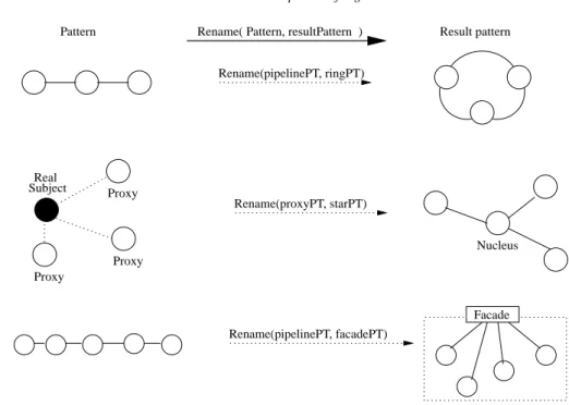
For the Rename operator, the cardinality of the pat-terns being renamed may be important in determining whether the operator can or cannot be applied (see Ta-ble 2). For instance, any topological pattern may be renamed into any other topological pattern, indepen-dently of the cardinality of the pattern. For example, a Pipeline pattern can be transformed into a Ring pat-tern, by connecting the first and last components of the
Pipeline (see Fig. 13). Similarly, a Pipeline can be
transformed into a Star, by taking one of the Pipeline’s components as the nucleus of the Star pattern, with the other components becoming satellites. Similarly, any non-topological pattern can be restructured into a
topo-Fig. 10. An example of a pipeline template with an embedded pattern (a star) in the leftmost component. Real Subject Proxy Proxy Proxy Proxy Real Subject
Pattern Increase( Pattern, 2 ) Result pattern
Fig. 11. The Extend and Reduce operators can be applied to the selected design patterns but not to the topological patterns.
Real
Subject Proxy Real
Subject Proxy a Proxy b
Facade
Facade
Facade
Pattern Extend( Pattern, element ) Result pattern
Fig. 12. Examples of the Extend operator over the Proxy and Facade Pattern Templates.
logical pattern, as long as the cardinality of the original pattern is maintained. For example, in Fig. 13, a Proxy pattern template containing three proxies is renamed into a star, which will have three satellites. These struc-tural operators therefore transform one pattern to an-other one within the same class. Additional transfor-mation may be undertaken by a user directly using an editor – although this does not provide any checking that the transformation will leave a pattern class invari-ant. Also, when using the Rename operator, the cardi-nality of the pattern template must be preserved. For example, it is not possible to rename a pipeline pattern with five elements into an Adapter, because their
car-dinality is different. However, the same pipeline can be renamed into a facade by annotating one of the ele-ments of the pipeline as the facade component, and the other elements as the sub-system classes (see Fig. 13).
5.2. Structural operators in use
This section gives some examples of the application of structural operators in the context of the application introduced in section 2. Figures 14 and 15 describe a possible sequence of steps to build the PSE configura-tion shown in Fig. 1, according to the patterns identified in Figs 7 and 8.
Proxy Proxy Proxy Real Subject Nucleus Facade Rename(proxyPT, starPT) Rename(pipelinePT, ringPT) Rename(pipelinePT, facadePT) Result pattern Pattern Rename( Pattern, resultPattern )
Fig. 13. Examples of the Rename operator over a Pipeline and a Proxy Pattern Templates.
problem solver and the database system). two component place holders (for the Step 2 - Creation of a pipeline PT with
Step 3 - Creation of a star PT for the database system (the frontend will be the nucleus and the slaves will be the satellites).
into the pipeline PT built in step 2. Step 4 - Embedding of the star PT Step 1 - Creation of a ring PT with three component place holders (for the problem steering interface).
solver, the monitoring service, and the
STEP 2:
STEP3: STEP 1:
STEP 4:
Fig. 14. Initial steps for building the PSE depicted in Fig. 1.
In step 1 (Fig. 14), the user creates a ring pattern template (PT) with three place holders to represent the components connecting the Problem Solver, the Mon-itoring service, and the Steering Interface. Next, the user creates a pipeline PT with two component place holders to represent the connection between the Prob-lem Solver and the Database System (step 2). This pipeline will be embedded in the first component place
holder of the ring, but first the user must create a PT to represent the Database System. In step 3, the user creates a star PT with three satellites that will be instan-tiated to the Database sub-systems. In step 4, the user applies the Embed structural operator over the pipeline PT with the star PT as argument, to be embedded in the second component place holder of the pipeline PT.
struc-Real Subject Proxy Proxy Adapter Adaptee Database system Problem solver Adapter Interface Steering Proxy Proxy
structural operator to the proxy PT. Step 8 - Application of the Increase
Step 9 - Embedding of the adapter PT (step 6) into the ring defined in. step 5.
PT into the third element of the ring PT.
Step 10 - Embedding of the proxy
Step 11 - Instantiation of all PTs with services.
Step 7 - Creation of a proxy PT for the steering interface. Step 6 - Creation of an adapter PT for the monitoring service.
STEP 5: Monitoring service STEPS 9, 10 and 11: STEPS 7 and 8: STEP 6:
Step 5 - Embedding of the pipeline PT defined in step 4, into the ring PT defined in step 1.
Fig. 15. Final steps for building the PSE depicted in Fig. 1.
tural pattern to include the pipeline PT obtained in step 4 into the first component place holder of the ring PT (previously defined in step 1). Next, the user creates an Adapter PT template to represent the Monitoring service (step 6). In steps 7 and 8, the user creates the structure for the Steering Interface (which will be ac-cessed by other users). To achieve this, the user creates a Proxy PT and then its proxy elements are increased by one through the application of the Increase struc-tural operator. In steps 9 and 10, the user embeds the Adapter PT and the Proxy PT in the ring’s second and third component place holders, respectively. Finally, in step 11, the user instantiates all pattern templates with the selected services. The user may now apply the ap-propriate Behavioural Patterns (e.g. as defined in sec-tion 3.5), and run the applicasec-tion using the Behavioural Operators to control its execution.
As a final remark, the user may eventually apply the structural operators again to reconfigure the applica-tion. For example, to perform a post-mortem analysis of the data produced by the Problem Solver as illus-trated in Fig. 4 (see section 2), the user may apply the
Rename structural operator to transform the ring into
a pipeline, and define the Database system as the first element of the pipeline.
5.3. Semantics of behavioural operators
In this sub-section we focus on the semantics of the Execution Operators which act upon pattern instances.
Pattern instances are structural pattern templates which have been assigned a behaviour pattern, and within which components have been already bound to exe-cutable component instances.
The Execution Operators can be divided into two groups. The first group controls the execution of a pattern instance, and includes: Start, Terminate, Stop,
Log, Resume, Repeat, Restart, Limit, and Steer. As
pre-viously mentioned, the applicability of these operators depends on the kind of runtime environment available. For instance, the Globus system may support particular execution mechanisms that are not supported in Legion, etc. For now, we assume the existence of at least the following operations – and the ability to communicate these requests to the underlying runtime system: to start running the component instance; to suspend/stop the current execution by temporarily saving the exe-cution status; to resume the exeexe-cution from the saved status; and to terminate the execution of the component instance. The second group of Execution Operators al-lows changes to the coordination and reconfiguration of pattern instances, and includes: ChangeDependencies and Coordinate. Currently, we limit these changes to the pattern interactions. The examples that follow are restricted to the first group of execution operators.
For illustration purposes we describe the semantics of the execution operators using a synchronous model,
namely the CO OPN/2 formalism [30,31]. For
and Stop act synchronously over all component
in-stances contained within a pattern. Hence, the invo-cation of the Start operator would imply invoking, si-multaneously, the start operation on all component in-stances. It is also possible to consider cases where the invocation of components is asynchronous – however, we restrict our analysis for now for the synchronous case – primarily because of the particular benefit the
CO OPN/2 tool we use offers in undertaking such an
analysis.
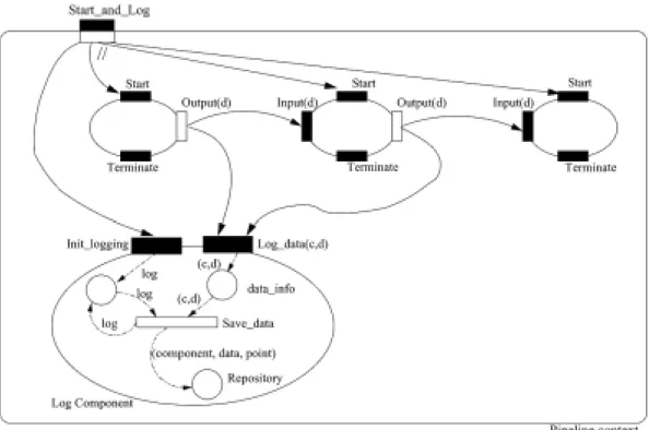
Figure 16 gives an application example of the Start and Terminate operators over a particular instance of
a pattern. The notation used is adapted from the
CO OPN/2 formalism [30], which provides Object-Oriented abstractions for modelling systems, and where synchronisation between object invocations can be modelled. Moreover, the CO OPN/2 formalism allows the functionality of each object to be represented as a Petri-Net – where data flow in the Petri-Net can model abstract data types. The objects in CO OPN/2 are seen by us as components. Figure 16 shows an example of a pipeline instance with three components, where each component is represented as an ellipse. As we are not, at this stage, concerned with the internal behaviour of components, we do not show Petri-Net blocks for these. The input ports (method calls) available on a component are represented by black rectangles along the border of the ellipse. Similarly, the output ports (or Gates) are represented as white rectangles. Syn-chronisation between components is achieved if there are arrow transitions connecting the component ports. This means that the methods associated with the ports are invoked synchronously. As such, the figure shows that the output port (Output(d)) of the leftmost compo-nent in the pipeline instance is synchronised with one of the input ports (Input(d)) of the middle component. As soon as the Output method is invoked, the Input method in the other component is invoked as well, and data is exchanged in the process. Likewise, the output port (Output(d)) of the middle component is synchro-nised with the port Input(d) of the rightmost compo-nent. In this way we represent a simplified kind of
Producer/Consumerbehaviour between the com-ponents of the pipeline.
Another important aspect of modelling with CO OP N/2 is the notion of a context – which in the figure is represented as a rectangle with round corners. A context is an entity encapsulating a set of components and the coordination rules that constrain those compo-nents. As with components, contexts also have input and output ports. Using the CO OPN/2 formalism, we
represent context’s ports as bi-coloured rectangles. In the inport ports, the dark part of the rectangle is on the outside of the context and the white part is on the in-side, and in the output ports is the opposite. In Fig. 16 there is a single context which represents a pipeline instance encapsulating three components. The invoca-tion of the Start method over the pipeline context im-plies the simultaneous invocation of the Start method of every component. We represent this simultaneous invocation by the simultaneity symbol // which belongs to the CO OPN/2 formalism. The simultaneity symbol is one of the synchronisation policies that the formal-ism provides. The other two policies are the sequence (the methods are invoked in sequential order) and the
alternative or nondeterminism (the method to be
exe-cuted is selected in a non-deterministic way among a set of available alternatives).
The Terminate operator has a similar behaviour to the Start operator, as shown in Fig. 16. The invocation of Terminate over the pipeline implies the simultaneous invocation of the Terminate method at all component instances.
The semantics of the Stop operator implies the im-mediate suspension of the execution of all component instances – hence it is similar to the Terminate operator. Using this operator, however, also causes the state of all component instances to be recorded. Figure 16 could be extended to represent the Stop operator by including an extra component in the pipeline context. This extra component would be responsible for collecting, simul-taneously, the execution state of all components – prior to terminating the execution of a component.
The semantics of the Resume and Log operators are related. While the latter implies saving the execution state at well identifiable points, the former is used to continue the execution of the pattern from one of sev-eral points identified by the Log operator. Figure 17 represents an example of the Log operator for storing data flowing in the pipeline instance of Fig. 16. In the example, we assume that the Log operator is invoked at the same time as the Start operator, and that the logging operations are realised by the Log component instance. The figure shows a Petri-Net representing a possible behaviour for the component supporting the Log func-tionality. The component used for logging data must be started simultaneously with the execution of other com-ponents – hence the Init logging method call. Subse-quently, whenever an output is generated by a pipeline stage, the Log data method is invoked, causing data to be stored into a Repository. The identity of the com-ponent which generated the output in the pipeline is
Output port (Gate) Simultaneity // Legend: Input port (Method) Synchronisation Pattern instance (Context) Component instance Start // // Terminate Output(d) Start Input(d) Start Start Input(d) Output(d)
Terminate Terminate Terminate
Fig. 16. Example of the Start and Terminate operators over a pipeline pattern instance.
Fig. 17. Example of the Log operator invoked simultaneously with the Start operator over a pipeline instance.
also recorded via Saved data (the c parameter in the
Log data method identifies the component).
For the Repeat operator it is necessary to provide a counter to record the number of times a pattern instance has been executed so far. It is also necessary to identify when the execution must terminate. Such an operator is particularly useful for supporting loops in scientific codes. An example of the Repeat operator can be pro-vided by extending Fig. 16 with the following elements: the pipeline context would have a new output port, e.g. end of execution, which would be automatically invoked at the end of the pipeline instance’s execution; a new context encapsulating the pipeline context would
be added; another component would be created in the outmost context that would represent the behaviour of the Repeat operator. This component would imple-ment a counter, initialised with the number of times the pipeline pattern would have to be repeated. The counter would be decremented synchronously with the invocation of the output port “end of execution”.
The Restart and Limit operators are similar in the sense that both depend on the notion of time for con-trolling a pattern. The Limit operator waits until the time value received as input expires – followed by the termination of the pattern instance managed by this op-erator. The Restart operator waits for the expiration of
the value held by the input time token, and invokes the start operation over the pattern it manages. Figure 18 gives an example of the semantics of the Restart op-erator when applied over the pipeline instance of the example in Fig. 16. Figure 18 adds a new context (Restart context) to Fig. 16, which encapsulates two components: one component is a timer which generates a tick at a specific time interval (e.g. a second); the sec-ond component represents the steps necessary for the restart operator. One of the transitions in the Petri-Net in this second component decrements the time interval received as argument at each tick of the timer, and keeps the result in place counter. When the counter reaches zero, a second transition is fired which launches the restart of the pipeline’s execution and initialises again the place counter with the original time interval (kept in the place time).
5.4. Behavioural operators in use
Figures 2 and 3 (section 2) describe a re-configuration example where the Monitoring service is replaced with a more complex service (Monitoring and Statistics
Ser-vice). Applying the Stop behavioural operator enables
the complete workflow to be terminated. Alternatively, the user might also apply the Stop operator over in-dividual patterns – such as the Proxy pattern instance that represents the Steering interface. The user must then replace the Adapter pattern with an instance of the
Monitoring and Statistics Service. Finally, the Restart
operator is applied to this new service (and eventually also to the Proxy pattern instance that represents the Steering Interface).
Having illustrated the application of structural and behavioural operators, next section describes the cur-rent implementation status.
6. Implementation Issues
This section describes the existing implementation of structural patterns and structural operators over the Triana environment. It also points out the continua-tion of the work on the implementacontinua-tion of behavioural patterns and operators.
6.1. The triana environment
Triana [19] is a Java-based workflow environment that supports application construction based on
dis-tributed components. Application execution results
from the collaboration between various network Peers (see [20]), which act both as clients (for local users’ requests) and as servers (for remote peers’ execution requests). Locally, each peer may access existing Grid services to execute high-throughput computations.
Through the Graphical User Interface (Fig. 19) pro-vided with Triana, users have access to services/tools (e.g. components for Signal Processing, Mathematical Calculations, etc.) that can be easily composed for building scientific applications. Users drag and drop components from the toolbox onto the scratch pad on the right side, and create a workflow by dragging cables that connect components together. Sender components are connected through output ports (or nodes) on the right-side, to receivers’ input ports (on the left-side). Users may also group selected components together into a component which represents the entire set. This “group component” also has input and output ports for connecting the group (and some of its hidden elements) with other components.
In Triana, execution follows the data-flow model: as soon as data arrives to a component’s input port, the service it represents is launched. Moreover, users may define which parts of the workflow may be executed remotely. The local Peer makes the necessary requests to remote Peers, collects the results, and displays them through the GUI. Execution may be supported by each Peer itself or may be realised by accessing a local re-source manager (e.g. Globus GRAM [13]).
6.2. Structural patterns and operators in triana
Structural Patterns are available in Triana’s toolbox as normal components (from a graphical perspective). The user just has to drag and drop them into the scratch pad and initialise them. For example, Fig. 19 shows a Ring PT and a Star PT that resulted from the initiali-sation of DrawRing and DrawStar, respectively. Each pattern template represents a set of component place holders called DummyUnits, which can be instantiated to other PTs or tools from the toolbox. DummyUnits are connected together according to the PT’s specific structural Pattern (i.e. ring, star, etc).
Structural Operators are available as parameters to pattern templates. For example, Fig. 20 shows the ap-plication of the Embed structural operator to the Ring PT. To use this, the user must invoke the Ring’s PT pa-rameter window to specify that the Pipeline PT should be embedded into the first Ring PT’s place holder (called DummyUnit). The Pipeline PT already has an an embedded Star PT. This example shows one of the
Pipeline context // // Terminate Output(d) Start Input(d) Start Start Input(d) Output(d)
Terminate Terminate Terminate
Start Restart(time_interval, pipeline) Time_ticker tick Restart context get_tick get_interval counter decrement_ interval launch_ restart t t t do_restart pred(t) t 0 t t time
Fig. 18. Example of the Restart operator over a pipeline instance.
steps to build the structure shown in the example de-scribed throughout the paper.
Structural pattern templates are implemented as groups in Triana. The group contains: a) the connected DummyUnits, and b) a control task that keeps track of the number of component place holders (and their connections), listens to relevant events (like requests to instantiate DummyUnits), and supports the execution of the structural operators.
The user may now compose an application by com-bining PTs with existing components, and may save them as a group component in the toolbox for later reuse. Once an application has been constructed – one or more behavioural patterns may be used to specify the data and control flows between components.
6.3. Usage scenario: Galaxy simulation
To illustrate the use of PTs in Triana, we utilise a “Galaxy Formation” code example. The example in-volves generating the position of particles and sub-sequently animating these – using a combination of
“DataReader” and “Animation” modules from Triana. A data file is loaded by a single Data Reader Unit within Triana, and passed to all the Triana nodes. Nodes then buffer the data for future calculations. Note that the data file could be copied beforehand and distributed in a parallel way also. The loaded data is then separated into frames, distributed amongst the various Triana servers on the available network and processed to calculate the column density using smooth particle hydrodynamics. These types of simulations can usually generate large data files containing snapshots of an evolving system. They are therefore quite representative of the types of applications that may be executed over Grid infrastruc-ture. In this particular example, after undertaking a simulation run, a snapshot is produced – and which is independent of others over time. This suggests that any data analysis on frames can be carried out indepen-dently. Grid resources are used in this instance to dis-tribute and remotely process data frames, which finally return a small image to the visualisation/controlling client. The images can be subsequently re-assembled
Fig. 19. The Triana Graphical User Interface.
Fig. 20. Application of the Embed Structural Pattern to the Ring Pattern Template.
in real-time into the correct chronological order to gen-erate a smooth animation.
Galaxy and star formation simulation codes gener-ate binary data files that represent a series of particles, along with their associated properties as a snap shot in time. The user of such codes would like to visualise
this data as an animation in two dimensions, with the ability to vary the perspective of view, and project that particular two dimensional slice and re-run the anima-tion. Due to the nature of the data, each frame or snap shot is a representation at a particular point in time of the total data set. It is possible to distribute each time
Fig. 21. The animation is supported by a pipeline PT which is embedded in the nucleus of the star PT.
Fig. 22. An example of a component place holder instantiation.
slice or frame over a number of processes and calcu-late the different views based on the point of view in parallel.
The Galaxy formation example may be represented by a Star PT, where the nucleus contains the actions necessary to generate and control the animation exe-cution, and the satellites represent image processing and analysis actions. In this way, the same animation can be simultaneously analysed/processed in different ways. Figure 21 shows a Star PT with three compo-nent place holders – the satellites (DummyUnit1 and
DummyUnit2), and the nucleus (DummyUnit). As the
animation is developed in stages, these are represented by a Pipeline PT. Figure 21 shows the Pipeline PT em-bedded in the nucleus of the star by selecting the embed structural operator, and by identifying the embedding position (DummyUnit).
Figure 22 shows the Star PT with the embedded Pipeline PTs, to support the image processing activities required to generate the animation. The next step in-volves instantiating the place holder (named
DummyU-nit) of the pipeline (in this case a DataFrameReader
is selected from the Triana toolbox) – as illustrated in Fig. 22. Figure 23 shows the final configuration, with