v
Acknowledgements
It is time to thank everyone who have been by my side and contributed somehow for the achievements made in and through this job.
First, to my family, my wife Anabela Carvalho, thank you for your support, for always stand by my side, encouraging me during this journey, for the understanding, strength, and motivation on the importance of ending this phase. My daughters Lara and Leonor whom so many times I did not gave the proper attention because I was focused on the work. To my mother whom was a cornerstone on my academic progress, my sister, brother in law and nephews to the proud they have on my achievements.
A special thank you to my supervisor Ricardo Correia and my co-supervisors Duarte Gomes and José Costa Teixeira, they have always supported my questions and doubts, and advised me on the right path to follow.
To Raphael Oliveira and Diogo Lajas which gave me essential help on the final phase of tests in this project.
To Sectra Medical Systems, who sponsored this Master degree, giving me the freedom to went to classes and time to dedicate to write and develop this project, thanks to make this possible!
A word of appreciation to all my MSc colleagues, some of them will be fellows for the journey that is live, the faculty, professors, some of them that are bright minds, and all staff from CINTESIS. A special thank you to António Poças, whiteout whom this project could not be possible, for his help on programming this tool and the advices on how to do that, you are really a bright mind!
To everyone who have crossed my steps and somehow helped me or advised me, contributing for the reality of this project.
vii
Abstract
Introduction: During the last years, healthcare institutions have been working with the aim to have paper-free hospitals. Different vendors present different solutions for several departments, affirming to contribute to a more efficient and effective patient care. The fact that these systems often need to exchange data within each other leads to extremely complex environments. The usage of ad-hoc agreements to exchange data between different systems and the usage of non-conformant standards endangers the possibility to change end-living systems. Even when communication standards are used, healthcare institutions often have complications, the lack of resources from institutions capable of auditing new integrations allows vendors to abuse on the ambiguous definitions of HL7 v2.x configurations which may result in unwanted behaviours in the workflows.
Objective: The main goal of this thesis is to develop a tool capable of, accordingly with the selected IHE profile, identify failures on the HL7 v2.x conformance in interactions between two systems. Methods: We will start by analysing in depth the workflow set by IHE for the radiology and laboratory departments, and then translate that information into the configuration files identifying the optionality on the message fields and the workflows for the transactions to be made. Use case scenarios have to be defined to have a better understanding on the tool usage, and the system architecture documented explaining the relation between the different used classes. Finally, we will define the tests to be made to evaluate the prototype efficiency and accuracy.
Implementation: We described the system requirements and all processes since storing the message into the ProfIHEller prototype database, validating syntax and workflows until the final output shown in a front-end web page.
Results: Tests were conducted based on more than 20.000 messages, using the IHE SWF profile to validate the results. We divided the tests in two separate sections, one that returns the accuracy on validating the syntax, and other on the workflow. The final results were calculated based on truth tables. Regarding the syntax validation, the system was 100% accurate, with predictive positive and negative values equal to one, the detected errors were then classified according with their criticality. As for the workflow validation, we detected some false positive values, even so, the system was able to correctly identify approximately 94% of the non-conformant workflows correctly, while the negative predictive value result was 1, meaning that all messages considered to have a valid workflow, indeed had a valid workflow.
Conclusion: Our main objective was fulfilled. We were able to create a tool that can identify failures on the conformance in interactions between two systems with a very high-accuracy. As for our secondary objectives, also accomplished we were able to develop a front-end web page, containing
in real-time information on the processed messages, and warnings for the identifying errors, thus giving institutions the capability to evaluate their existing HL7 v2.x integrations based on the configured profile. The validation rules on syntax and workflow are based on configuration files stored with the application. The created prototype proved useful to institutions as a way to evaluate their HL7 v2.x compliance with IHE profiles.
Keywords: Interoperability, HL7, RIS, HIS, IHE, IHE Integration Profiles, standards, IHE compliant
ix
Resumo
Introdução: Nos últimos anos, as instituições de saúde têm-se esforçado pelo objetivo de terem “hospitais sem papel”. Existem diferentes soluções, de diferentes fornecedores para diversos departamentos, todas afirmando que contribuem para um cuidado mais eficiente e eficaz do paciente. O facto de estes sistemas muitas vezes terem que trocar informação entre eles transforma os ambientes hospitalares em cenários bastante complexos, os acordos ad-hoc entre fornecedores para integrarem as suas aplicações [1] a utilização de configurações não conformes de acordo com os standards dificulta a possibilidade de substituição de sistemas em fim de vida [2]. Mesmo quando são utilizados standards, muitas vezes as instituições deparam-se com problemas e a falta de recursos por parte das instituições capazes de auditar as configurações permite aos fornecedores abusar da ambiguidade de certas definições nas configurações HL7 v2.x que muitas vezes resultam em problemas no normal fluxo de trabalho.
Objetivo: O principal objetivo desta tese é o desenvolvimento de uma ferramenta capaz de, de acordo com o perfil IHE configurado, identificar falhas na conformidade das mensagens HL7 v2.x nas interações entre dois sistemas.
Métodos: Começaremos por analisar os fluxos de trabalho definidos pela IHE para os departamentos de Radiologia e Laboratório, depois iremos traduzir esta informação para os nossos ficheiros de configuração, definindo a opcionalidade dos campos por segmento e os fluxos de trabalho que deverão estar mapeados para simular a transação. Serão definidos cenários de utilização de forma a melhor entender a utilização da ferramenta, seguido da arquitetura do sistema onde se documenta e explica a relação entre as diferentes classes. No final serão definidos os testes a fazer para avaliar a eficiência e precisão na deteção de erros.
Implementação: É feita a definição dos requisitos de Sistema e de todos os processos desde que a mensagem é guardada na base de dados do protótipo ProfIHEller, o processo de validação de sintaxe e de fluxo de trabalho até à fase em que o resultado da avaliação é mostrado numa página de front-end.
Resultados: Foram efetuados testes com base num sub-set com mais de 20.000 mensagens, utilizando o perfil IHE SWF para validar o fluxo de trabalho. Os testes foram divididos em dois, um avaliava a precisão na avaliação sintática, o outro de fluxo de trabalho. Os resultados finais foram calculados com base em tabelas de verdade. Na validação sintática o sistema foi 100% preciso, com valores preditivos positivos e negativos igual a um, os erros de sintaxe detetados foram analisados e classificados de acordo com critérios de criticidade. Relativamente à validação de fluxo de trabalho, o sistema identificou corretamente cerca de 94% das avaliações de não conformidade, enquanto que
o valor preditivo negativo foi 1, o que quer dizer que todas as mensagens avaliadas como tendo o perfil válido, realmente estavam corretas.
Conclusão: O nosso objetivo principal foi cumprido, fomos capazes de criar uma ferramenta capaz de identificar falhas na conformidade das interações entre dois sistemas com uma precisão bastante significativa, como demonstrado nos resultados obtidos. No que diz respeito aos objetivos secundários, também cumpridos, fomos capazes de desenvolver uma página web que contém em tempo real a informação das mensagens processadas, como avisos sobre os erros encontrados, dando a possibilidade e capacidade às instituições de avaliar as suas integrações HL7 v2.x de acordo com o perfil configurado. As regras para validação sintática e de fluxo de trabalho são definidas em ficheiros de configuração, guardados com a aplicação. O protótipo provou ser útil às instituições como forma de avaliar a conformidade das suas configurações HL7 com perfis IHE
Keywords: Interoperability, HL7, RIS, HIS, IHE, IHE Integration Profiles, standards, IHE compliant
xi
Preamble
At an early phase of my professional career, in 2003, I had the luck to start working within the healthcare environment, first in Hospital Santo António as an IT technician, where I have learned the core of an institution IT environment, working with and supporting different applications, integrating new services with the aim of “paper free” hospital. In 2011 I was selected to be the IT responsible for the Centro Integrado de Cirurgia Ambulatória, CHP – Porto, where I was an “one man army” supporting the whole structure from the hardware to the databases. In 2012 I followed a different path and from customer I became part of a vendor’s team in Sectra Medical Solutions, in Sectra I was made aware of the importance on standards as HL7 and DICOM, I first heard the word interoperability and became more and more interested in those areas. At this moment, I am responsible for the Iberian migration PACS team, where all details need to be taken importance to be able to configure new systems, integrate them with other vendor’s equipment’s and configure them using HL7 communication. The IHE Technical frameworks is a very important “handbook” while investigating the best way to integrate the systems and study their workflow.
Although my degree is in Electronics, I have always worked in IT, more concretely Medical IT. From that to applying to the Medical Informatics Master degree in Faculdade de Medicina da Universidade do Porto it was a small step, I felt the need to learn more and this degree program was from all possibilities the one that aroused more curiosity.
The motivation factors that lead me to perform this study where the profession experience, that shows me that many times vendors try to follow the easiest path to perform an integration, causing many times problems for which hospitals do not have solutions. The creation of a tool capable of audit HL7 integrations in real time is an innovation factor, capable of create and share knowledge to the institutions were this tool can be used to prevent failures and support a better service to the patients.
Technology is a science in constant evolution, IS can bring great benefit to both entities and patients, as long as they follow the standards and all work within a common end.
xiii
Contents
Acknowledgements ... v Abstract ...vii Resumo ... ix Preamble ... xi Contents ... xiiiAbbreviations and Acronyms ... xv
List of figures ... xvii
List of tables ... xviii
1. Introduction ... 1.1 Introduction... 1
1.2 Goals and expected results ... 3
1.3 Research question ... 3
1.4 Document structure ... 4
2. State of the Art ... 5
2.1 Introduction... 7
2.2 HL7 v2.x ... 7
2.3 HL7 v3 /CDA ... 9
2.4 HL7 FHIR ... 9
2.5 Radiology department ... 10
2.6 Hospital Information System (HIS) ... 10
2.7 Radiology Information System (RIS) ... 11
2.8 Picture Archiving and Communication System (PACS) ... 12
2.9 Laboratory Information System (LIS) ... 12
2.10 Integrating the Health Enterprises (IHE) ... 12
2.10.1 Laboratory Testing Workflow (LTW) ... 14
2.10.2 Scheduled Workflow (SWF) ... 15
2.11 Real-time intelligent systems ... 16
2.12 Related work: ... 17
2.12.1 DICOM VALIDATOR ... 17
2.12.2 Intelligo Enterprise Manager ... 17
3. Methodologies ... 19
3.1 Design ... 21
3.3 Use case ... 25 3.4 System architecture ... 26 3.5 Tests description ... 29 4. Implementation ... 32 4.1 Implementation ... 34 5. Results ... 39 5.1 Syntax validation ... 41 5.2 Workflow validation ... 44 6. Discussion ... 49
6.1 S.G.1 - Give HI control on HL7 integrations ... 51
6.2 S.G.2 - Develop a front-end web page ... 51
6.3 S.G.3 - Configure the validation profile ... 52
7. Conclusion ... 53
7.1 Future Work ... 56
xv
Abbreviations and Acronyms
ADT Admission Discharge and TransferANSI American National Standards Institute CDA Clinical Document Architecture
CIDES Department of Health Information and Decision Sciences
CENTESIS Center of Research in Health Technologies and Information Systems CIS Central Information System
CR Computed Radiography
CT Computed Tomography
DB Database
DICOM Digital Imaging and Communications in Medicine EHR Electronic Health Record
FHIR Fast Healthcare Interoperability Resources
HIMSS Healthcare Information and Management Systems Society
HL7 Health Level 7
HIT Health Information Technology HIS Health Information Systems
IEEE Institute of Electrical and Electronics Engineers
IT Information Technologies
IS Information Systems
ISO International Organization for Standardization IHE Integrating the Healthcare Enterprise
JSON
LIS Laboratory Information System LTW Laboratory Test Workflow
MR Magnetic Resonance
MSH Message Header
NEMA National Electric Manufacturers Association NCVHS National Committee on Vital and Health Statistics OML Laboratory Order
ORM General Order Message
ORU Unsolicited Transmission of an Observation PACS Picture Archiving and Communication System
RIM Reference Information Model RIS Radiology Information System RSNA Radiology Society if North America
SNOMED-CT Systematized Nomenclature of Medicine-Clinical Terminology
SWF Scheduled workflow
TCP
US Ultra Sonography
xvii
List of figures
Figure 2.1 - OSI Model [19] ... 7
Figure 2.2 - HL7 message delimiter values [19] ... 8
Figure 2.3 - ADT^A04 HL7 message example [20]... 8
Figure 2.4 - HL7 v3/CDA example [23] ... 9
Figure 2.5- HL7 FHIR message structure example [25] ... 10
Figure 2.6- RAD-4 Use Case roles [36] ... 13
Figure 2.7 - IHE Technical Framework development process [37] ... 14
Figure 2.8- LTW Workflow description [38] ... 15
Figure 2.9 - Scheduled Workflow Diagram obtained from IHE_RAD_TF-2[36] ... 16
Figure 2.10- DICOM Validator [[3]] ... 17
Figure 2.11- Intelligo Enterprise Manager Error queue ... 18
Figure 3.1 - IHE RAD-12[34] ... 21
Figure 3.2- IHE RAD-4[34] ... 21
Figure 3.3 - IHE RAD-28[34] ... 22
Figure 3.4 - IHE LAB- 1 / LAB-2 [41] ... 23
Figure 3.5- IHE LAB -3 [30] ... 24
Figure 3.6 - ProfIHEller use case diagram... 26
Figure 3.7- System Architecture ... 27
Figure 3.8 - ProfIHEller DB diagram ... 27
Figure3.9 - ProfIHEller Back-End Class Diagram ... 28
Figure3.10 - ProfIHEller Front-End Class Diagram ... 29
Figure 3.11 - ProfIHEller validation rules... 29
Figure 3.12- SWF State transition diagram ... 30
Figure 3.13 - SWF profile validation rules ... 30
Figure 3.14 - Structured Report state transition diagram ... 30
Figure 3.15 - Structured report validation rules... 31
Figure 4.1- HL7 processing ... 34
Figure 4.2 - ProfIHEller architecture ... 35
Figure 4.3 - ProfIHEller StateTester rules configuration ... 36
Figure 4.4 - ProfIHEller Validator optionality rules configuration ... 37
Figure 4.5 - ProfIHEller Front-End application ... 38
Figure 5.1- ProfIHEller validation errors detected ... 43
List of tables
Table 3.1 - ADT message structure[23] ... 21
Table 3.2- ORM message structure[23] ... 22
Table 3.3 - ORU message structure[23] ... 22
Table 3.4- OML message structure[30] ... 23
Table 3.5 - Required fields per segment ... 25
Table 3.6 - Table of truth ... 31
Table 4.1 - ProfIHEller MSG_RAW table field content... 34
Table 4.2 - Designations for optionality [19] ... 37
Table 4.3 - Technical Requirements for ProfIHEller solution ... 38
Table 5.1 - SWF test subset ... 41
Table 5.2 – ProfIHEller messages in database ... 41
Table 5.3 - ProfIHEller validation errors ... 42
Table 5.4 – Syntax error classifications ... 42
Table 5.5 - ProfIHEller validation - table of truth ... 43
Table 5.6 - ProfIHEller Workflow detected errors ... 45
Table 5.7 - ProfIHEller workflow errors Not correct ... 46
1
Introduction and motivation
1.1 Introduction
During the last years, there has been a boom on the usage of information technologies (IT) in healthcare environments, Health Level 7 (HL7) and Digital Imaging and Communications in Medicine (DICOM) are known acronyms when talking about interoperability in healthcare and almost all clinical applications use at least one of them due to the need to exchange information with other systems from different vendors[2].
The fact that data is exchanged between systems does not mean it is correctly interpreted, or that the configuration made to integrate these systems is correct. Vendors configure their systems to receive what they want, and store it how they want, many times not obeying to standards, using nondocumented custom structured values, endangering future system changes or replacements. Institutions often do not have people with enough knowledge to audit the configurations made, so they are approved as long as the institutions needs are fulfilled. By doing this the ability to future change end-living systems or make extra adjustments became difficult and many times almost impossible.[2] This is verified in a study conducted in 2016 by Raphael Oliveira, et al [1] that concludes that in Portugal, the HIS interoperability state is chaotic, as most of the solutions use database views on other applications instead of a standard based information trading protocol, increasing complexity and costs of the overall solution.
Data can only be successfully shared to create integration workflows, contributing to a better healthcare service quality if it is compliant with the standards[3].
Defining Interoperability is not an easy task, one can easily find different approaches, while all must be considered valid:
• Accordingly with the Healthcare Information and Management Systems Society (HIMSS) “In healthcare, interoperability is the ability of different information technology systems and software applications to communicate, exchange data, and use the information that has been exchanged” [4]. • The Institute of Electrical and Electronics Engineers (IEEE), definition for interoperability is “The capability to communicate, execute programs, or transfer data among various functional units in a manner that requires the user to have little or no knowledge of the unique characteristics of those units” [5].
• The International Organization for Standardization (ISO) states that interoperability is
“the capability of two or more functional units to process data cooperatively” [6].
• According to National Committee on Vital and Health Statistics (NCVHS) there are three possible categorizations when talking about Interoperability [7]:
o Foundational: Data is exchanged between systems however the receiving application is not required to interpret it;
o Structural: The format of the data exchange is well defined, ensuring that systems can interpret it at the data field level, however, this will not assure that the data content is identically interpreted by both parts, thus being susceptible to different interpretations by both sending and receiving applications;
o Semantic: Requires that the information is unambiguously exchanged by both sending and receiving applications, meaning that all structure, codification and vocabulary included are well defined and understood, thus meaning that both
2
applications can use the exchanged data [7, 8];
Healthcare organizations worldwide aim to reach this last level of interoperability. Health Level 7 has been working on standards based on semantic interoperability, using this requirement as base for its third version of HL7 standards, this effort resulted in the birth of HL7 Clinical Document Architecture (CDA). According to NCVHS [9] this was a very important step as it enforces the highest level of interoperability in healthcare IT.
Standards can be perceived as set of rules and procedure definitions on how the perform a certain action, improving access to information and reducing costs [10, 11].
Among other benefits, Standards help to speed up the development process for new solutions, ensure that different parties can communicate and provide the availability to perform quick adjustments on the configurations complying with changing business parameters [11].
Standards can be categorized accordingly with the way they are created as: • Ad hoc, a standard usually created and only used within one institution;
• De facto, when a set of rules or system is used so massively that become a standard; • Governmental, when standards are defined and legislated by a government;
• Consensus, when standards are created and maintained by groups of interested parties [10]. Standards can also be categorized based on their purpose, like the communication definition (e.g. TCP), how to represent clinical information (e.g. SNOMED-CT) or even how to define the building of a medical image header (e.g. DICOM).
As for communication within Health Information Systems (HIS), HL7 is considered to be the most used standard [12].
Due to its complexity, flexibility and extensive standard options it is very hard to evaluate if an HL7 configuration follows the standards, thus leading to unwanted behaviours, errors or malfunctions in the workflows, resulting in patient’s non-satisfaction and worst healthcare quality services[3]. Since HIS are involved in complex environments, involving different kind of people, systems, languages and workflows, interoperability between HIS is only possible if there is an effort by vendors on cooperation, internal institution departments join efforts to a final achievement; management teams struggle to keep their assets motivated; and most important, that political and legal issues are considered and dealt with.
Exchanging healthcare information implies first of all an understanding that patient privacy and data confidentiality have to be assured [7, 9, 13].
One of the biggest problems regarding the implementation of standards as sentenced by Andrew Tanenbaum’s is that “The nice things about standards is that there are so many of them to choose from” [6, 13, 7].
It is very difficult for the institutions trying to implement new standards to choose one due to the wide range of available ones, their complexity and costs associated. Define workflows, test them, evaluate and select the standard to be used inside an institution is a complex and time consuming operation, leading to high financial costs [13]. Due to this fact, worldwide healthcare professionals and industry representatives, have been working together to define technical frameworks for standards-based interoperability among HIS, leading to the creation of the Integrating the Healthcare Enterprise (IHE). IHE main goal is to improve the way HIS share information, by promoting definitions on how to use well-established standards such as HL7 and DICOM. IHE is divided into domains such as radiology, ophthalmology, pharmacy, laboratory and others. For each domain, IHE
3 has a technical committee whose main goal is developing and document integration profiles, these documents finally result in technical frameworks which are shared with healthcare professionals globally. IHE also integrates planning committees, which, provide training sessions, workshops, and demos on real-case scenarios, among other, tasks meant to encourage the adoption of the knowledge provided on
the technical frameworks and integration profiles so they can be adopted within the enterprises and institutions. For this reason, IHE profiles and their standards are becoming the basis for interoperability based on open architectures [6, 7, 11, 14]. Despite all these efforts, most healthcare institutions are still far from achieving fully interoperable environments. A study conducted in 2010 in Portugal by L. Ribeiro, J. P. Cunha and R. Cruz-Correia concluded that only 16% of all possible connections between HIS were made in Northern Portuguese hospitals [15]. The American Hospital Association concluded that, even though the majority of hospitals can send and receive information between HIS, only 40% of hospitals can use the exchanged information [15, 13]. The heterogeneity of data between systems, the existence of old non-standardized systems, and the lack of proper IT infrastructures, prevent data mapping, as well as the adoption of standards and compliance to IHE profiles [1, 12, 8]. Changing this reality still translates in high economical and technical costs, requiring a sustainable and multidisciplinary approach [18].
On this thesis, we propose the creation of a system that, based on the content of the HL7 messages exchanged between systems, is able to accordingly with the selected IHE profile, identify failures on the HL7 v2.x conformance in interactions between two systems.
The main contributions of this work include:
• Innovation: Based on the research made, we were not able to find any system that can, in real time, evaluate the conformance of HL7 transactions.
• Information Share: Give power, knowledge and awareness to the institutions, providing them a tool capable of evaluate their existent interactions, returning information on their configurations conformance based on the selected IHE profile.
1.2 Goals and expected results
The main goal of this thesis is to develop a tool capable of, accordingly with the selected IHE profile, identify failures on the HL7 v2.x conformance in interactions between two systems.
The secondary objectives are:
• Give Healthcare Institutions the capability to evaluate their existent HL7 integrations; • As an add-on, develop a front-end web page, returning all information on the messages
processed, warning System Administrator of possible problems. • As an add-on include the possibility to configure the validation profile.
• At the end of this job we expected to have a system capable to identify required fields not filled in and workflows that are non-conformant based on the configured Integrating the Healthcare Enterprise (IHE) profiles, leading to a less rentable usage of healthcare resources and most important to a negligent treatment given to patients by healthcare professionals, returning the validation value stating if the exchange is valid or not.
1.3 Research question
The research question that lead us to perform this thesis was:
“Can an IHE conformance validation system for exchanged HL7 v2.x messages between different actors on a Healthcare institution be developed?”
4
1.4 Document structure
This thesis is divided in seven chapters with the following summary:
1 Introduction – Contains an explanation on the problem that lead to choose the theme to perform this thesis, we have a definition of interoperability, the way interoperability may be achieved within HIS, standards and their close connection to interoperability, the motivation, goals, expected results and finally the research question.
2 State of the art – this chapter describes the technologies and standards in study on this thesis, containing examples on IHE profiles and their interpretation, followed by examples of related works.
3 Methodologies – The chapter starts with the analysis of different transactions, describing the mappings needed to create the validation rules, in the second sub-chapter there is a storyboard describing the utility of the developed tool, a use case on the third sub-chapter describing the SWF IHE profile in a real-case scenario, followed by the system architecture and the test description in the fourth and fifth sub-chapters. 4 Implementation – Contains the description on all tools and processes, identifying the
functions and their finality on storing, validating and displaying the final results on the validations made.
5 Results – this chapter is divided in two sub-chapters, the first one contains the test results on the syntax validation and the second on the workflow validation, including statistical results and the error classification.
6 Discussion – In this chapter we discuss each proposed objective and the achievements made.
7 Conclusion – Contains all important findings made during the writing of this thesis and a sub-chapter containing future work proposals
5
7
2.1 Introduction
Data quality is of major importance on hospital environments, these environments are becoming more heterogeneous, thousands of applications can be found installed on several departments and all claim to communicate on a transparent basis, but this is only possible if this communication is based on standards.
The most used way to make sure the data exchanged between healthcare applications is successfully interpreted is the usage of the Health Level 7 (HL7) communication protocol.
HL7’s principal goal is to produce communication specifications that may lead to a decrease on the incompatibility between systems and is one of the main solutions for the interoperability existent issues. In 1987 the American National Standards Institute (ANSI) started the development of this communication protocol, which is used to share clinical, administrative and financial Information between systems through text messages. This protocol was built over the seventh layer in the OSI Model (see Figure 2.1 bellow) [1, 7, 9, 10]:
Figure 2.1 - OSI Model [19]
HL7 currently supports 3 versions of this protocol, V2.x, V3.x/CDA and FHIR.
2.2 HL7 v2.x
HL7 V2.x standard is the most widely used standard in healthcare systems at this moment, v2.x messages do not have a precise and distinct information model, meaning that the definitions for many fields are ambiguous, several ones are optional, providing flexibility on their configurations, but on the other side, leading to erroneous interpretations, the configurations need to be agreed and documented to different systems achieve interoperability.
The work implemented during the construction of this thesis has focused on auditing the content of HL7 v2.x messages, which is widely used on the exchange of structured messages between different HIS to share either clinical or administrative information such as billing details, examination
8
scheduling’s, patient admissions, discharge and transfer or observation results. Some examples of message types and their purposes:
• Admission, discharge, transfer patient
e.g.: ADT (Admission [^A08], Discharge [^A03] and Transfer [^A02]) • Query Patient data
e.g.: QBP (Patient Demographics and Visit Query [^ZV1]) • Order Scheduling or status change
e.g.: ORM/OML (Order Message [^O01]) • Reporting
e.g.: ORU (Observation result [^R01]) • Financial Management (DFT/BAR) • Patient Bills (BAR^P01)
• Financial transactions (DFT^P03)
An HL7 message is composed by several lines, in which every line is named as segment which contains several data fields. The message delimiters can be found in field MSH-1 and are specified in detail in Figure 2.2:
Figure 2.2 - HL7 message delimiter values [19]
One can identify the message type and the consequent intended action based on the content of field MSH-9, as an example we can see on Figure 2.3 an ADT^A08 message, used to update the demographic data of a patient in the HIS.
Figure 2.3 - ADT^A08 HL7 message example [20]
Systems can communicate for different purposes like analysis or research [13]. The Systematized Nomenclature of Medicine-Clinical Terminology (SNOMED-CT) is the entity who represents the clinical information by defining medical terms, their codes and how they shall be used. SNOMED-CT promotes uniformity of meaning in stored and exchanged information, aiding its processing and automatic analysis [10]. When talking in medical images, the most used standard is Digital Imaging
9 and Communications in Medicine (DICOM). This standard defines the image header format and a set exchange services like, storage, print and visualization. DICOM enhances the interoperability, making possible to exchange and share images between systems from different vendors [13, 20].
2.3 HL7 v3 /CDA
HL7 v3 is based on an object-oriented data model (Reference Information Model (RIM)) and aims to avoid the v.2.x ambiguity by specifying the structure and semantics allowed to be used on the exchange of clinical documents. Until this version the exchanged data was limited to be used in between medical information systems, but from this version on, a new standard (Clinical Document Architecture – CDA) was introduced to share clinical documents [21], this type of document can include text, images sounds or other multimedia contents with both structure and semantic well specified. It is encoded in XML as illustrated in Figure 2.4, consisting in a header that contains the document classification and information on all involved entities, such as the patient or the encounter and the body, usually divided into document sections, containing narrative blocks[22].
According with the standard, CDA’s main characteristics are: • Persistence
• Stewardship
• Potential for authentication • Context
• Wholeness • Human readability
Figure 2.4 - HL7 v3/CDA example [23]
2.4 HL7 FHIR
HL7 Fast Healthcare Interoperability Resources (FHIR) is the latest version of the HL7 communication family used to exchange electronic healthcare information, it can be formatted either in XML as shown in Figure 2.5 or JSON format. It is built based on Resources, that can be assembled into working systems, thus solving some of the clinical and administrative know issues, with less effort and costs[23]. HL7 FHIR specification can be divided in three parts:
• Documentation – Describing resources and data types, codes, XML and JSON format definitions
• Implementation – Users can use RESTful Architecture Programming Interfaces (API’s) as clinical documents or as a service.
10
infrastructural.
As HL7 FHIR is oriented to be used on web applications, it’s resources can be reused across systems to retrieve a specific resource or version history. Since all specifications are stored online, they can be linked from a properties resource to its data type, giving the possibility to be used in mobile applications, electronic health record based data sharing and among vendors [24].
Figure 2.5- HL7 FHIR message structure example [25]
2.5 Radiology department
The X-Ray was accidentally discovered in 1895 by Wilhelm Rontgen while conduction experiments by discharging electrical current in a highly-evacuated glass tube [30]. This discover made a revolution in medicine, for the first time it was possible to minimize the “diagnostical subjectivity” from the clinical signs, thus, leading to the discovery of a new “way to look into the body” [26] through the representation of structures so far invisible and only shown through autopsies or on the first surgical procedure attempts. Roentgen hand X-Ray that needed a radiologic exposure of more than 20 minutes would travel the world showing this new technique.
In the 70s the ultra-sonography (US) arrived, exploring the ultra-sounds properties, and new forms of energy to obtain medical images. This techniques impact was and are of major importance since this is an innocuous tomographic technique able to perform real time examinations [31]. The Radiology department has as main goals to diagnose, and report findings to the clinician staff. Nowadays imaging reports are notifications used by an actor (e.g., radiologist) which analyses information (e.g., Medical images) and elaborates a conclusion (e.g., radiology report) in which relevant findings are enumerated and sent to a recipient (e.g., referring clinician), which based on the given information uses it as a base support to patient care decision making (e.g., surgery).
2.6 Hospital Information System (HIS)
Introduced in the 1960s, this systems are used to manage patient data, visits and invoicing in the HealthCare institution [27]. Through this system it’s possible to:
11 • Admit a patient and manage its administrative data
• Receive payments and manage patients cash flow • Schedule Radiology or Laboratory examinations
Nowadays, HIS include the integration of all administrative, clinical and financial applications, addressing the various departments in an institution needs. Through these systems it is possible to manage data to the clinical, laboratory, nursing, radiology, finance among other departments, HIS aim to integrate with all hospital applications, thus collecting all demographic, clinical and financial information on each patient, delivering benefits such as:
• Enhancement of the information integrity. • Transcription error reduction.
• Ambiguous information entry reduction [28].
2.7 Radiology Information System (RIS)
A RIS is commonly found and used in radiology management and designed to support operational workflow. It is a repository of patient data and reports. RIS can also be used to manage other departments and imaging specialties like nuclear medicine or radiotherapy [29].
These systems are usually associated with several functionalities, like: • User access control and patient consent
o Users have roles, giving them permission to use certain functionalities like sign reports, or view clinical information
o Patient consents are stored after being signed authorizing certain medical acts. • Patient demographics and alerts
o Patient demographics must be constantly updated with resource to a common Master Patient Index (MPI) or a Patient Administration System (PAS) o Relevant patient alerts such as allergies or infection risks must be stored and
exchanged with other care record systems. • Electronic and paper-based requesting
o It must be able to process the referrals received from other electronic remote requesting systems (ERR).
o It must also be able to process manual referrals. • Booking and scheduling
o It must manage bookings and scheduling supporting both imaging and non-imaging schedule procedure steps (e.g. a radioisotope injection and a radioisotope image).
• Worklists and folders
o Worklists are lists of examination procedures required for defined work cases like CT’s to report or exams per room
o Folders are directories which can be used to group examinations to support the radiologist activity like teaching or research folders.
• Examination details
o It should be capable to record all information related with a given procedure, like the dose, technique, contrast or persons involved in the procedure and their role. • Reporting and report coding
o A RIS should support all aspects of the reporting workflow from the generation of reporting work lists through dictation, word processing, report verification and issuing
• Image tracking • Stock control • Billing • Integration
o IHE defines the transactions required between systems to achieve functional integrated solutions, recurring to integration profiles such as the Scheduled workflow (SWF), the Patient Information Reconciliation (PIR), the Reporting Workflow (RWF) or the Access to Radiology Information (ARI), among others.
12
2.8 Picture Archiving and Communication
System (PACS)
PACS’s are HIS used to archive and distribute digital medical images through network infrastructures, mainly used on radiology departments to store images acquired through medical equipment’s like Computerized Topographies (CT), Magnetic Resonance (MR), etc. The stored images can then be used as base to a clinical report, and distributed to be consulted on any place within the institution or to be sent to other institutions [30].
This concept has been created by the National Electric Manufacturers Association (NEMA) [20], the Radiology Society if North America (RSNA), and a group of companies and universities in the United States of America (USA) [31].
The base tasks that can be performed through a PACS system are [31]: • Distribute images to remote workstations
• Short and long-term storage to magnetic or optical storages • Network interaction with other equipment’s and systems such as:
o DICOM Query/Retrieve o DICOM Worklist o DICOM Print
2.9 Laboratory Information System (LIS)
LIS are commonly found and used in laboratory management. The core functions of a LIS system are [32]:
• Sample management
o Receive and register samples in the laboratory o Sample and data tracking
• Instrument and application integration • Electronic data exchange
o Export data to other HIS.
The main purpose of a LIS is to improve laboratory operations by cutting down on manual tasks, automatizing as much handling processes as possible, recording information that otherwise would need to be written or typed, reducing errors and saving time. LIS have become a prerequisite for any laboratory deployment and this systems made possible that internal laboratory operations are an almost paper-free exercise [33].
2.10 Integrating the Health Enterprises (IHE)
IHE was created in 1998 by a group of persons with a common feel “promote the use of standards to achieve interoperability of health information technology (HIT) systems and effective use of electronic health records (EHRs)”. It is mainly constituted by volunteers from known healthcare system vendors, experts from Healthcare IT and other stakeholders from several domains (clinical and operational), all working in a common aim, to get consensual standard solutions, leading to solve critical interoperability problems.IHE works like a forum, promoting the interoperability between all HIT, describing problems and possible solutions concerning software integrations on clinical applications, providing best-practice cases and guides to install or configure standards and providing the best workflow options on the communication between solutions.
13 From the implementation guides created by those, named IHE profiles, this consortium publishing these guidelines for public comment, and after that for implementation trials by vendors and system developers, on the definitions provided on those we can find the following terminologies:
Actor: The HIT or some of its components that produces, manage or exchange clinical data[34]; Transaction: The procedure that will be triggered, which may have multiple interactions (e.g. in transaction RAD-2 (Placer Order Management) we identify four actions: order request, order cancel, order change and cancellation of an examination in-progress)[35];
Interaction: The smallest piece of the transaction, that defines the event triggered.
Profile: Set of functional components from a given HIT, describing its interactions, based on a defined transaction set, defining actors and roles per transaction.
In Figure 2.6 there’s the representation of the Procedure Scheduled, corresponding in the IHE Technical Framework to RAD-4 [36].
In this case, there are 3 well defined actors:
- The Order Filler (Department System Scheduler, usually the RIS system); - The Image Manager (PACS system);
- The Report Manager (RIS system); Each actor has a defined role:
- The Order Filler is responsible to Schedule Procedures (Order requests/exams) and keep its information up-to-date (exam update, cancellations, etc.).
- The Image Manager after receiving the information from the Order Filler will use this information on the image management.
- The Report Manager after receiving the information from the Order Filler will use this information on the report management
Department System Scheduler/Order
Filler
Procedure Scheduled
Image Manager Report Manager
Figure 2.6- RAD-4 Use Case roles [36]
The creation of pairs of actors/roles, intends to recreate the reality on hospital environments, and define the interactions that should be fulfil on the communications between two entities.
IHE promotes yearly Connectathons, events in which vendors and developers can test their system implementations conformance with IHE profiles.
14
department Technical Framework, providing HIT administrators and developers, standard solutions proven to address known interoperability problems, this process is displayed in Figure 2.7.
Figure 2.7 - IHE Technical Framework development process [37]
IHE profile conformance can be specified as a requirement when requesting for proposals by purchases, vendors can also publish their IHE Integrations Statements when they are certified to be compliant and have successfully implemented IHE profiles on their products.
IHE main goal is to warranty that all patient information, and necessary data for is treatment are correct and available once they are needed [14].
2.10.1 Laboratory Testing Workflow (LTW)
The LTW profile supports all in vitro tests performed in all lab specialities (excluding anatomic pathology), for both identified and unknown orders, related with identified, unidentified and misidentified patients.As in Figure 2.8 we can see the graphical definition of the LTW profile, containing the transaction specifications for new orders h specimens are collected and identified by the Order Placer LAB-1, new orders where specimens are collected externally and identified by the Order Filler LAB-2, results exchanged LAB-3, and the interaction between the Order Filler (usually the LIS) and the equipment’s LAB-4/LAB-5 [38].
15
Figure 2.8- LTW Workflow description [38]
2.10.2 Scheduled Workflow (SWF)
The SWF Profile contains the detailed specifications to keep data integrity and services continuity within the radiology department. In Figure 2.9 we can see the transactions defined to keep patient and order data consistency RAD-1/RAD-12, as well as the description on the schedule procedure and image acquisition steps RAD-4/RAD-13/RAD-42.
This profile includes the information on how should information flow, including information on the archive status of images RAD-8/RAD-10 and their availability to make part of other workflow steps like reporting or query retrieve to other systems RAD-14/ RAD-16. It has also definitions on how should information flow to keep the Order Placer up-to-date regarding appointments notifications and also provide a central coordination on processing and reporting completion status.[36]
16
↓ Pt. Registration [RAD-1] ↓ 12: Patient Update [RAD-12] Pt. Registration [RAD-1] ↓
Patient Update [RAD-12] ↓ ← Placer Order Management [RAD-2] → Filler Order Management [RAD-3] → Appointment Notification [RAD-48]
ADT ↓ Query Images [RAD-14] ↓ Retrieve Images [RAD-16] Image Display Storage Commitment [RAD-10]↓
↑ Modality Image Stored [RAD-8] Storage
Commitment [RAD-10] ↑
↓ Creator Images Stored [RAD-18] ↓ Procedure Scheduled [RAD-4]
↑ Image Availability Query [RAD-11] ↓ Procedure Updated [RAD-13]
↑ Performed Work Status Update [RAD-42] ↓ Performed Work Status Update [RAD-42] ↑ Instance Availability Notification [RAD-49]
← Query Modality Worklist [RAD-5]
Evidence Creator
Performed Procedure Step Manager
↑ Modality PS in Progress [RAD-6] ↑ Modality PS Completed [RAD-7] ↑ Creator PS in Progress [RAD-20] ↑ Creator PS Completed [RAD-21]
→ Modality PS in Progress [RAD-6] → Modality PS Completed [RAD-7] → Creator PS in Progress [RAD-20] → Creator PS Completed [RAD-21]
← Modality PS in Progress [RAD-6] ← Modality PS Completed [RAD-7] ↓ Creator PS in Progress [RAD-20] ↓ Creator PS Completed [RAD-21]
Order Placer Acquisition Modality Image Manager Image Archive DSS/ Order Filler
Figure 2.9 - Scheduled Workflow Diagram obtained from IHE_RAD_TF-2[36]
2.11 Real-time intelligent systems
Information systems (IS) are systems that store, analyse, process and disseminate information for a specific purpose[39]. They are projected and developed focused on the objectives of the organization, giving support to the business regardless the environment. Since 1980 many organizations are emphasizing Expert Systems to solve complex issues. With the constant evolution of the business, decision makers require proactive systems that can use data in real-time [40].
Real-time IT are over the radar of the scientific community accordingly to Dasgupta and Vankayala [41], developing and supporting this kind of systems is challenging, and all aim to reach 0% downtime. In this case, the human factor can lead to mistakes or workflow failures, often due to circumstances (a patient is ready to the exam but he is not available in the worklist and the radiologist have to insert patient data manually on the modality) or stress (the latency between systems can cause some delays) [41].
17
2.12 Related work:
In our aim to develop a tool capable of audit HL7 messages we have found some other tools that have also contributed to the produced work, for all the systems found, there are two that should be referred:
2.12.1 DICOM VALIDATOR
The usage of web services to validate DICOM files conformance by Silva, Jorge, et al in [3] is a great example on innovation tools developed to help system administrators keep their data on track. This platform developed by DETI (University of Aveiro, Portugal), can validate DICOM files, verifying the presence of mandatory DICOM tags/fields, also supporting the capability to define supported values, like the ones that can define the Patient Administrative Sex (“M”,” F”,” O”), among other options that can help a PACS Administrator identify and validate problems on their DICOM files.
In Figure 2.10 we can see a screenshot of the output of an DICOM file validation.
Figure 2.10- DICOM Validator [[3]]
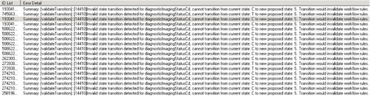
2.12.2 Intelligo Enterprise Manager
Intelligo Enterprise Manager is a commercial HL7 Hub solution, sold by Medicallis[42], this tool is an HL7 Gateway that has a built-in Wokflow manager in which it is possible to define rules for state transitions based in which, the tool will identify transitions that would not comply with the workflow rules defined ahead. All transactions considered invalid are logged and displayed as in Figure 2.11 on the embedded log error queue [42].
18
19
21
3.1 Design
To be able to configure properly the system we first had to do an in-depth analysis of the workflow set by IHE for the radiology and laboratory departments, and then translate that information into configuration files.
As for the SWF IHE profile, we have interpreted the transactions referred on Figures 3.1, 3.2 and 3.3:
Figure 3.1 - IHE RAD-12[34]
The transaction RAD-12 is used by the Order placer to add or modify patient demographics and other information related with the patient, ADT^A08 messages are used to perform these operations, in Table 3.1 we can see the structure of required segments on ADT messages, and the document source where the optionality field rules were collected from.
Table 3.1 - ADT message structure[23]
Segment Description Chapter in HL7 v2.5 documentation
MSH Message Header Chapter 2
EVN Event type Chapter 3
PID Patient Identification Chapter 3
PV1 Patient Visit Chapter 3
22
Transaction RAD-4 is used to trigger new schedule orders, or change an existent order (cancel, reschedule, order changes) from the Order Filler into the Image Manager. To perform these operations is used the ORM^O01 message type, in Table 3.2 we can see the structure of required segments on ORM messages, and the document source where the optionality field rules were collected from.
Table 3.2- ORM message structure[23]
Segment Description Chapter in HL7 v2.5 documentation
MSH Message Header Chapter 2
PID Patient Identification Chapter 3
PV1 Patient Visit Chapter 3
{ORC Common Order Chapter 4
OBR} Observation Request Chapter 4
Figure 3.3 - IHE RAD-28[34]
Transaction RAD-28 is used to export structured reports from the Report Manager to a repository, in this case from the RIS to the PACS. To perform these operations is used the ORU^R01 message type, in Table 3.3 we can see the structure of required segments on ORU messages, and the document source where the optionality field rules were collected from.
Table 3.3 - ORU message structure[23]
Segment Description Chapter in HL7 v2.5 documentation
MSH Message Header Chapter 2
PID Patient Identification Chapter 3
[PV1] Patient Visit (Accordingly with the RAD-TF4 [36] this segment is only required case PV1-19 is required by regional or national appendices)
Chapter 3
OBR Observation Request Chapter 7
{OBX} Observation Results Chapter 7
23
Figure 3.4 - IHE LAB- 1 / LAB-2 [41]
Transaction LAB-1 is used to trigger new schedule orders, or change an existent order (cancel, reschedule, order changes) from the Order Placer into the Order Filler. LAB-2 transactions are used the opposite way, from Order Filler into Order Placer. To perform these operations the OML^O21 message type is used, in Table 3.4 we can see the structure of required segments on OML messages, and the document source where the optionality field rules were collected from.
Table 3.4- OML message structure[30]
Segment Description Chapter in HL7 v2.5
documentation
MSH Message Header Chapter 2
PID Patient Identification Chapter 3
PV1 Patient Visit Chapter 3
ORC Common Order Chapter 4
24
Order Result Tracker
OUL or ORU, Result status S
Order Filler
New order received or generated
ACK, (applicative acknowledgement)
OUL or ORU, Result status I Reception and
acceptance of specimen
ACK, (applicative acknowledgement)
OUL or ORU, Result status R Technically validated
results available
ACK, (applicative acknowledgement)
OUL or ORU, Result status P (partial) or F (final) Clinical validation
of results
ACK, (applicative acknowledgement)
OUL or ORU, Result status C Correction of
results previously sent as clinically
validated ACK, (applicative acknowledgement)
Figure 3.5- IHE LAB -3 [30]
As per the LAB-3 transaction, the message structure is the same as per the radiology SWF profile, since ORU^R01 messages are used, we referred to the content of Table 3.3 to the evaluation of this message type.
The field optionality was defined accordingly with the definitions stated in the HL7 Messaging Standard v.2.5 Chapters 2, 3, 4, 5 and 7 [19, 43, 44, 45] , as defined in Table 3.5 the PV1-19 can be considered optional accordingly with the regional or national appendices. Table 3.5 contains the information of the fields defined as required on the validation rules.
25 Table 3.5 - Required fields per segment
SEGMENT SEQ LEN DT OPT ELEMENT NAME
MSH 1 1 ST R Field Separator 2 4 ST R Encoding Characters 7 26 TS R Message Date/Time 9 15 MSG R Message Type 10 20 ST R Message Control ID 11 3 PT R Processing ID 12 60 VID R Version ID
EVN 2 26 TS R Recorded Date/Time
PV1 2 1 IS R Patient Class
19 250 CX O Visit Number
PID 3 250 CX R Patient Identifier
List
5 250 XPN R Patient Name
ORC 1 2 ID R Order Control
OBR 4 250 CE R Universal Service
Identifier
OBX 2 2 ID R Value Type
3 250 CE R Observation Identifier 4 20 ST R Observation Sub-ID 5 26 TS R Observation Value 11 1 ID R Observation Result Status
3.2 Storyboard
Ricardo is an Hospital IT system administrator on hospital FMUP. He is also responsible for Laboratory and Radiology Departments Information Systems.
Today he is receiving calls from the radiology department stating that patient data is not arriving to the modalities via DICOM Modality Worklist, there are patients hanging on the waiting room more than two hours and already started to complain on the waiting time.
FMUP’s PACS system is the application responsible for providing this service to the modalities, before calling the PACS vendor, Ricardo remembers that FMUP has recently installed ProfIHEller, a real-time audit tool that monitors the HL7 communication between the two actors and is capable of identify possible breaches on the workflow or message syntax accordingly with the defined IHE profile.
He opens the application and realizes that the workflows are returning errors, Ricardo knows that modalities only receive the request data using DICOM Modality Worklist functionality on status NW (“New Order”) however this status is being overlapped and RIS is only sending status CM (“Order completed”) on all studies. That was the reason for those failures. After contacting the RIS provider, the messages were resent on the correct order, ProfIHEller was returning success transactions now, Ricardo called the Radiology department that confirmed that the problem was solved.
3.3 Use case
In Figure 3.6 we have the description on the use case of the ProfIHEller solution in a real case scenario. As the communication between the RIS and the PACS flows through an HL7 HUB, there
26
is a destination that forwards the HL7 messages from the RIS to the PACS and another one that picks the messages sent from the RIS and forwards them to the ProfIHEller database, thus the tool does not have any direct influence on the defined workflow.
The Radiology workflow has been interpreted based on schematics like the one shown in Figure 3.12 and from it the state machine rules have been created, also the message types for the workflow have been collected and based on those and the content of Table 3.5, the field optionality rules have been added to the validations configuration file.
Use case – On a normal working day in Hospital A, the radiology technician on duty finds that patients already admitted on the RIS does not have scheduling’s in the PACS, causing that even though the modalities can store images, those are not available to the referring clinician’s due to availability rules set on the institution’s PACS. The radiology technician calls the IT system administrator, who opens the ProfIHEller web page, and by ordering the messages by date notices that in the last 45 minutes there were no new messages processed on the tool. He is also able to confirm this in the HL7 Hub and immediately contacted the RIS provider to fix the problem.
Figure 3.6 - ProfIHEller use case diagram
3.4 System architecture
ProfIHEller system architecture can be defined as shown on Figure 3.7, HL7 messages will be sent from an HL7 message repository to a MirthConnect engine that will parse them and save their content to a database.
The database as shown in Figure 3.8 will be constituted by a main table identified as MSG_RAW, and four auxiliary tables, one containing the information on the syntax validations which will be named “MessageValidations”, other containing the workflow validations and state history named “MessageStates”, other containing the identifiers on the messages already validated, named “TestedMessages” and finally a table containing the patients identifiers, useful if we want to evaluate the message workflow (e.g an ADT message is always sent prior to a procedure schedule).
The validation engine is described in Figure 3.9, the HomeController class will be the main class, from which all other classes will be called from, it will start by picking the untested messages from the database, validate their syntactic content with resource to the configuration settings provided by calling the validator class. Then the statetester class will be invoked, thus validating the workflow against the set of defined rules. The information on this validation tests will be then saved back into
27 the database.
Finally, an MvcApplication shown in Figure 3.10 will, based on the content of the database deliver the information on the validations made in a front-end web page.
Figure 3.7- System Architecture
Figure 3.8 - ProfIHEller DB diagram
28
29
Figure3.10 - ProfIHEller Front-End Class Diagram
3.5 Tests description
To test the SWF profile, we will extract approximately 20-000 HL7 messages from a raw message log file.
The systems to be tested will be the RIS and PACS from the healthcare institution in test and the extracted subset will only refer to messages sent from the RIS to the PACS.
The messages to be tested will have dates comprehended between 2016-05-04 and 2016-05-31. The messages present in the subset need to follow the configuration present in the specification done by the vendors, these should be conformant with an international methodology workflow like the IHE SWF profile.
Customer documentation refers that fields OBR-25.1 and OBR-32.1 are mandatory, on a previous first analysis to the extracted subset we were aware that some messages does not have these field filled in, so, to prove the capability of the tool to identify those we will change the optionality from fields OBR-25.1 and OBR-32.1 for ORM^O01 messages from optional (“O”) to required (“R”) on the validations configuration file, all other fields optionality will be based on the content of Table 3.5. Based on this the validation.xml was configured as shown in Figure 3.11 bellow:
30
Figure 3.12 contains the transition diagram used to evaluate the IHE SWF profile, the translation from this to state machine rules used for these tests are shown in Figure 3.13.
Figure 3.12- SWF State transition diagram
Figure 3.13 - SWF profile validation rules
As for the Structured Report Export, described in the 2nd Volume of the Radiology IHE technical framework [36], in Figure 3.14 we can see the transition diagram in which the rules in Figure 3.15 were based.
31
Figure 3.15 - Structured report validation rules
The messages will be sent via TCP to the configured Mirth channel and finally, after the validation process finish the output will be analysed.
Time spent to process the all messages will be registered.
Possible failures or problems identified during the test process shall be documented.
To evaluate the capacity of the system to identify non-conformant HL7 messages, the validation results will be analysed with resource to truth tables as in Table 3.6.
Table 3.6 - Table of truth
Test\Output Not Valid Valid
Workflow is incorrect True Positive (TP) False Positive (FP) TP+FP
Workflow is correct False Negative (FN) True Negative (TN) FN+TP
Total TN+FN FP+TN Total
After that the ProfIHEller application efficiency must be calculated, for that we will calculate the values for:
Sensibility (S): The probability that a workflow is incorrect and is marked as Not Valid; ܵ = (ܶܲ + ܨܰ)ܶܲ
Specificity (E): The probability that a correct workflow is marked as Valid; ܧ = (ܶܰ + ܨܲ)ܶܰ
Prevalence (P): The proportion of Incorrect workflows within the total number of messages tested ܲ =ܧݎݎݎݏ (݊ݑܾ݉݁ݎ ݂ ݅݊ܿݎݎ݁ܿݐ ݓݎ݂݈݇ݓݏ)݊ (ݐݐ݈ܽ ݑ݈ܽݐ݅݊ ݐ݁ݏݐ݁݀)
Positive Predictive Value (PPV): The probability of a workflow to be marked Not Valid, is incorrect.
ܸܲܲ = (ܶܲ + ܨܲ)ܶܲ
Negative Predictive Value (NPV): The probability of a workflow marked as Valid, indeed is correct.
32
34
4.1 Implementation
The system was designed to run in Linux Ubuntu, thus avoiding extra Operating System licensing. All modules used are Open Source, we have used XAMPP to run MySQL, and apache, Mirth to receive HL7 messages and store information into the database, MonoDevelop to develop and test C# applications, system requirements are described in Table 4.3.
The system will receive messages from a central HL7 v2.x repository, through an installed instance of Mirth Connect. In mirth, a TCP Listener has been configured to receive HL7 messages and process them through a destination, this destination will simply parse the HL7 messages and insert the values of Message Control ID, the message in raw state and the message type into a MySQL database table (MSG_RAW), the system date will be calculated based on the local system date/time and not the message date/time as described on Table 4.1.
It was assumed that the Message Control ID is unique for a pair of audited systems, so it was used as primary key on the MSG_RAW table. Case the Message Control ID is not unique, the insert statement will fail and Mirth will retrieve a non-acknowledgment message, containing the information that it is trying to insert a non-unique value into the table. In Figure 4.1 we can see a schematic on the processing of HL7 messages in Mirth.
Table 4.1 - ProfIHEller MSG_RAW table field content
Table column Description Comment
MSG_CTRL_ID Message Control ID The unique identifier of the
message
MSG_RAW The raw message It is used to validate if the
mandatory
segments/sub-segments are present
SYS_DATE Local System Date
MSG_TYPE Message Type Obtained from the MSH.9 field
Figure 4.1- HL7 processing
ProfIHEller database structure is set as in Figure 3.8, as referred initially the Message Control ID (MSG_CTRL_ID) was considered to be unique and is used as primary and foreign key in all tables
![Figure 2.1 - OSI Model [19]](https://thumb-eu.123doks.com/thumbv2/123dok_br/15714465.1069664/29.918.163.757.407.816/figure-osi-model.webp)
![Figure 2.2 - HL7 message delimiter values [19]](https://thumb-eu.123doks.com/thumbv2/123dok_br/15714465.1069664/30.918.159.759.445.732/figure-hl-message-delimiter-values.webp)
![Figure 2.6- RAD-4 Use Case roles [36]](https://thumb-eu.123doks.com/thumbv2/123dok_br/15714465.1069664/35.918.191.707.652.895/figure-rad-use-case-roles.webp)
![Figure 2.7 - IHE Technical Framework development process [37]](https://thumb-eu.123doks.com/thumbv2/123dok_br/15714465.1069664/36.918.162.757.134.443/figure-ihe-technical-framework-development-process.webp)
![Figure 2.8- LTW Workflow description [38]](https://thumb-eu.123doks.com/thumbv2/123dok_br/15714465.1069664/37.918.164.755.93.388/figure-ltw-workflow-description.webp)
![Figure 2.9 - Scheduled Workflow Diagram obtained from IHE_RAD_TF-2[36]](https://thumb-eu.123doks.com/thumbv2/123dok_br/15714465.1069664/38.918.163.781.77.646/figure-scheduled-workflow-diagram-obtained-from-ihe-rad.webp)
![Figure 2.10- DICOM Validator [[3]]](https://thumb-eu.123doks.com/thumbv2/123dok_br/15714465.1069664/39.918.185.780.384.774/figure-dicom-validator.webp)
![Figure 3.1 - IHE RAD-12[34]](https://thumb-eu.123doks.com/thumbv2/123dok_br/15714465.1069664/43.918.233.682.237.473/figure-ihe-rad.webp)
![Table 3.2- ORM message structure[23]](https://thumb-eu.123doks.com/thumbv2/123dok_br/15714465.1069664/44.918.182.731.242.658/table-orm-message-structure.webp)
