Ahmad Kalthoum
Aluminium façades in modern construction
Ahmad Kalthoum
Aluminium façades in modern construction
Dissertation presented to the University of Aveiro to fulfil the necessary requirements of obtaining the master’s degree in Civil Engineering, held under the supervision of Dr. Paulo Jorge de Melo Matias Faria de Vila Real, Full Professor, and the co-supervision of Dr. Nuno Filipe Ferreira Soares Borges Lopes, Assistant Professor, Department of Civil Engineering, University of Aveiro.
“We're made of star stuff. We are a way for the cosmos to know itself.” – Carl Sagan –
o júri
presidente Profª. Doutora Maria Fernanda da Silva Rodrigues
Professora Auxiliar no Departamento de Engenharia Civil da Universidade de Aveiro
Prof. Doutor Joaquim Alexandre Mendes de Pinho da Cruz
Professor Auxiliar no Departamento de Engenharia Mecânica da Universidade de Aveiro (Arguente)
Prof. Doutor Paulo Jorge de Melo Matias Faria de Vila Real
Acknowledgment I would first like to thank my parents, for the endless support and encouragement throughout all my life.
I would also like to acknowledge my supervisor Prof. Dr. Paulo Vila Real and co-supervisor Prof. Dr. Nuno Lopes of the civil engineering department at the University of Aveiro, for their tremendous academic support and for consistently being available to offer their proper guidance throughout my entire academic life.
Plus, I would like to thank Martifer Alumínios S.A. team for the given opportunity of realization of the curricular internship and for their help in my integration.
I must express my gratitude to every team member of the Global Platform for Syrian Students organization, represented by the ex-president of Portugal Dr. Jorge Sampaio and his diplomatic advisor Dr. Helena Barroco, as this accomplishment would not have been possible without the precious opportunity they´ve granted me to continue my studies in Portugal.
Finally, I would like to thank every Portuguese friend helped me in any way to integrate and form my new life phase here in my second home Portugal.
Author
palavras-chave Alumínio, fachada, resistência ao fogo, montante, construção moderna, preparação de obra, Eurocódigo 9, vidro, fachada cortina.
resumo Esta dissertação tem como objetivo elaborar sistemas de fachada em alumínio e os materiais incluídos. Em complemento são apresentadas as atividades do estágio curricular realizadas durante seis meses na Martifer Alumínios, S.A.
A dissertação elabora os materiais frequentemente utilizados em sistemas de fachadas em alumínio e apresenta ainda as principais propriedades que definem as funcionalidades das fachadas que visam fornecer qualidades ao edifício como isolamento e impermeabilização.
O estágio curricular foi realizado na equipa de pré-construção da Martifer, incluindo a participação e desenvolvimento na realização de desenhos de aprovação e planos de fabrico no projeto que envolve a preparação de fachada do London Dock edifício C1.
O último capítulo desta dissertação elabora mais especificamente a resistência ao fogo de um montante de alumínio. Com base nos
Eurocódigos (EN 1990, EN 1991-1-2, EN 1999-1-1, EN 1999-1-2), foram concluídas as verificações de resistência ao fogo para um montante de alumínio com e sem proteção contra incêndio.
keywords Aluminium, façade, fire resistance, mullion, modern construction, site preparation, Eurocode 9, glass, curtain wall.
abstract This dissertation aims to elaborate in aluminium façade systems and the materials included and presents the activities in curricular internship held over six months at Martifer Alumínios, S.A.
This dissertation focuses on the commonly used materials in aluminium façade systems and presents the main properties that defines the functionalities of façades and provides the whole building with qualities like insulation and weatherproofing.
The curricular internship was held at the pre-construction team of Martifer, it included participation and development in the realization of approval drawings and manufacturing plans of London Dock building C1 façade construction project.
The last chapter in this dissertation elaborates more specifically in fire
resistance of an Aluminium mullion. Based on Eurocodes (EN 1990, EN 1991-1-2, EN 1999-1-1, EN 1999-1-2), the fire resistance verifications were
concluded for the studied aluminium mullion with and without fire protection considered.
Contents
1 Introduction ... 9 1.1 General considerations ... 9 1.2 Company background... 9 1.3 Internship objectives ... 10 1.4 Dissertation structure ... 11 2 Aluminium façades ... 152.1 Materials and its properties ... 15
2.1.1 Extruded aluminium ... 15
2.1.1.1 Classification of aluminium alloys ... 16
2.1.1.2 Heat treatment process ... 18
2.1.1.3 Extrusion process ... 19
2.1.1.4 Mechanical behaviour of cross-sections ... 20
2.1.1.5 Mechanical material properties ... 21
2.1.1.6 Thermal behaviour ... 24
2.1.1.7 Aluminium contact with other materials ... 26
2.1.2 Glass... 27
2.1.3 Steel ... 29
2.1.3.1 Structural steel properties ... 30
2.1.3.2 Steel bracket ... 32
2.1.3.3 Galvanized Steel Sheet ... 32
2.1.4 Glass Reinforced Concrete – GRC ... 33
2.2 Types of façades ... 34
2.2.1 Curtain wall ... 34
2.2.1.1 Modular façade (Unitized system) ... 36
2.2.1.2 Traditional façades (Stick system) ... 37
2.2.1.3 Façade type Aufsat ... 38
2.2.1.4 Façade type VEC ... 38
2.2.2 Ventilated façade systems ... 39
3 London Dock building C1 Project ... 43
3.1 Architecture ... 43
3.2 Façade preparation ... 45
3.2.1 Design phase ... 46
3.2.2 Approval phase ... 46
3.2.4 Installation phase ... 49
4 Fire resistance of aluminium mullion ... 53
4.1 Fire action ... 55
4.1.1 Nominal fire ... 56
4.1.2 Natural fire ... 56
4.2 Mechanical actions produced by a fire scenario ... 57
4.3 Aluminium members temperature θal, d estimation ... 58
4.3.1 Simplified equation for Non-protected member ... 58
4.3.2 Simplified equation for Protected member ... 62
4.4 Fire Resistance checking domains ... 64
Figures List
Figure 1: Martifer S.A.'s Headquarter (©Martifer, 2019) ... 9
Figure 2: Energy cost of various construction materials (GRID-Arendal, 2009) ... 16
Figure 3: Extruded aluminium cross-section (Shah, 2015) ... 20
Figure 4: Extrusion die (©MetraSPA, 2019) ... 20
Figure 5: Classification of cross-sections (EN1999-1-1, 2007) ... 21
Figure 6: Continuous models in the form σ = σ(ε) (EN1999-1-1, 2007) ... 22
Figure 7: Modulus of elasticity of aluminium alloys at elevated temperature (EN1999-1-2, 2007) ... 24
Figure 8: Specific heat of aluminium alloys as a function of the temperature (EN1999-1-2, 2007) ... 25
Figure 9: Relative thermal elongation of aluminium alloys as a function of the temperature (EN1999-1-2, 2007) ... 25
Figure 10: Glass with air barrier in aluminium frame (India business directory, 2019) ... 28
Figure 11: Laminated glass with PVB interlayer (Glazcon, 2018) ... 29
Figure 12: Insulated Glass Unit known as IGU (Glazcon, 2018) ... 29
Figure 13: Specific heat capacity of Structural steel as a function of the temperature (EN1993-1-2, 2005) .. 31
Figure 14: Relative thermal elongation – Steel (EN1993-1-2, 2005) ... 31
Figure 15: Cast-in Channel connected to the reinforcement (©Hilti, 2019) ... 32
Figure 16: Galvanizing Process (Group Flat Roll, 2019) ... 32
Figure 17: Spraying process (WikiMartifer, 2019) ... 34
Figure 18: Premix process (WikiMartifer, 2019)... 34
Figure 19: Continuous curtain wall (WikiMartifer, 2019) ... 35
Figure 20: interrupted curtain wall (WikiMartifer, 2019) ... 35
Figure 21: The Installation of modular façade (©Martifer, 2019)... 37
Figure 22: Traditional façade system (WikiMartifer, 2019) ... 38
Figure 23: Aufsat façade; Aluminium - Wood (WikiMartifer, 2019)... 39
Figure 24: Façade VEC (Navarra, 2018). ... 39
Figure 25: Chimney effect (WikiMartifer, 2019) ... 39
Figure 26: Fixing members (WikiMartifer, 2019) ... 39
Figure 27: St George, London Dock, Building C1 (Berkeley, 2019) ... 43
Figure 28: London Dock building C1. a) Elevation - West; b) Elevation - East; c) Elevation - North; d) Elevation - South (Berkeley, 2019) ... 44
Figure 29: Typical floor Plan - London Dock Building C1 (©Martifer, 2019) ... 45
Figure 30: Approval drawing of a modular unit details (©Martifer, 2019) ... 47
Figure 31: Galvanized steel sheet Details - Manufacturing plan (©Martifer, 2019) ... 48
Figure 33: Module – 3D (©Martifer, 2019) ... 53
Figure 34: Horizontal Section - Module (©Martifer, 2019) ... 53
Figure 35: The studied mullion – Detail (©Martifer, 2019) ... 54
Figure 36: The studied mullion – Dimensions (©Martifer, 2019) ... 54
Figure 37: Time-Temperature Curve ISO 834 (ResearchGate, 2019) ... 56
Figure 38: Natural fire stages Curve (TimberFirst, 2013) ... 57
Figure 39: Nomogram to obtain the temperature of unprotected aluminium profiles with clean surface (εm = 0,7), subjected to the ISO 834 curve, for different values of ksh Am/V (Vila Real, Lopes, & Pinho-da-Cruz, ESTRUTURAS DE ALUMÍNIO: NOMOGRAMAS PARA O CÁLCULO DA SUA RESISTÊNCIA AO FOGO DE ACORDO COM O EUROCÓDIGO 9, 2011) ... 60
Figure 40: Aluminium Temperature - Time Curve (Without protection) ... 61
Figure 41: Insulation – RWA45 (©RockWool, 2019) ... 62
Figure 42: Aluminium Temperature - Time Curve (With protection) ... 63
Tables List
Table 1: Numerical Designation for wrought alloys (Mazzolani, 1994) ... 17
Table 2: Numerical Designation for casting alloys (Mazzolani, 1994) ... 17
Table 3: Wrought aluminium alloys for structures (EN1999-1-1, 2007) ... 18
Table 4: Regions of material behavior (EN1999-1-1, 2007)... 22
Table 5: Mechanical and physical characteristics of pure aluminium ... 23
Table 6: Alloys and characteristic values (EN1999-1-1, 2007) ... 24
Table 7: 0,2% proof strength ratios ko, θ, for aluminium alloys at elevated temperature for up to 2 hours thermal exposure period (EN1999-1-2, 2007) ... 26
Table 8: Mechanical properties – Glass (Savić, 2013) ... 27
Table 9: Design values for Structural steel Coefficients (EN1993-1-2, 2005) ... 30
Table 10: GRC - Mechanical properties (WikiMartifer, 2019) ... 33
Table 11: Composition of curtain wall (WikiMartifer, 2019) ... 35
Table 12: Mullion - technical sheet ... 55
Table 13: Load categories (Vila Real, Incêndio em Estruturas Metálicas, 2003) ... 58
Table 14: Section factor Am/V for unprotected structural aluminium members (EN 1999-1-2) ... 59
Table 15: Excel Sheet's resume for Aluminium temperature Calculation – without protection ... 61
Table 16: Excel Sheet's resume for Aluminium temperature Calculation – with protection ... 63
Table 17: The Design Values of the studied member (©Martifer, 2019) ... 66
Table 18: Values of Rfi,d ... 66
1
Introduction
1.1
General considerations
The presented dissertation has been concluded by attending a curricular internship held at Martifer Alumínios, S.A. for 6 months, and accompanied with a parallel academic study case about the fire resistance of a vertical aluminium member.
The parallel academic study case was elaborated in a real case from one of the ongoing Martifer Alumínios, S.A. projects in London, UK.
1.2
Company background
In February of 1990, Martifer Alumínios, S.A. was formed and based in the Industrial Zone of Oliveira de Frades, Viseu, where its Headquarter continues up to now.
Martifer S.A. has three business areas, Metallic Constructions, Naval Industry and Renewables. Martifer started its activity in the shipbuilding and repair sector in 2008 with the acquisition of Navalria which is a shipyard with a strategic location in Aveiro port. Martifer Renewables acts as a developer of renewable energy, mainly in wind and solar power projects, being present in five countries: in the Iberian Peninsula, Central Europe and Latin America.
Martifer Metallic Constructions provides a global and innovative solutions in metal mechanical constructions and aluminium façades. Mainly aimed at leading highly complex projects, Martifer Metallic Constructions bases its development strategy on differentiation through quality engineering. The company is focused on three major geographic areas: Europe, the Middle East and Africa, and has industrial units that allow it, from those areas, to build the most complex projects in diversified places such as in Saudi Arabia, in Algeria, or France.
1.3
Internship objectives
The curricular internship took place in the offices of Martifer Alumínios S.A. in Martifer’s Headquarter in the Industrial Zone of Oliveira de Frades, Viseu. between 11/02/2019 and 15/07/2019, 32 hours per week.
The theme of the curricular internship is “Construction site Preparation/Management”, and it includes technical assistance and resources management for the construction site during the project and the execution phases.
The dissertation will be focusing on the ongoing project of London Dock building C1, a project consists of design, preparation and elaboration of the manufacturing plans of a curtain wall. The main objective of the internship is to participate in develop the following activities:
-
Technical analysis and structural design of Aluminium façades.-
Monitoring and technical-economic optimization of the construction site.-
Elaboration of aluminium façade designs for client approval.-
Preparation and modelling of manufacture plans of aluminium façades.-
Production of digital representations through designing computer software.-
Review of the commercial budget and production budgeting-
Construction site execution (productive resources management, technical preparation, analysis and/or review the project, general team coordination, billing and planning and costs control).In addition to the internship’s objectives, the academic study case is focusing and elaborating on the fire resistance of an aluminium vertical member (Mullion) for a real case from London Dock building C1 project.
1.4
Dissertation structure
Chapter -1- presents a brief background about the company where the internship takes place, the time schedule and general considerations
Chapter -2- presents an introduction about the materials used in façades and its mechanical and thermal properties. It presents also some types and solutions for façades used fabricated in Martifer Alumínios.
Chapter -3- elaborates in a specific construction site – London Dock Building C1 –, overviewing the architectural and structural point of views and presenting the series of job done for the façade design and preparation.
Chapter -4- presents a parallel academic work studying a fire action in vertical aluminium member (Mullion) in modular façade, with and without fire protection considered, verifying its stability in the resistance domain.
2
Aluminium façades
A façade is a frontage of a building that faces on to a street or open space. Architecturally it’s often the most important aspect from a design standpoint, as it sets the tone for the rest of the building. Form the engineering perspective, the façade is also a great importance for the impact on energy efficiency.
Aluminium façade system is an outer covering of a building as non-structural exterior wall. It’s typically designed with extruded aluminium framing vertical members called mullions and horizontal members called transom infilled with glass. A non-structural wall does not carry any structural load form the building other than its own dead load weight, it’s designed to resist the wind load, water infiltration and actions produced by accidental forces such as earthquakes and fire.
The wind loads are classified as variable fixed actions, it acts directly on façades and represented by simplified set of pressures whose effects are equivalent to the extreme effects of the wind action and calculated from the basic values of wind pressure with a mean return period of 50 years.
2.1
Materials and its properties
2.1.1 Extruded aluminium
Aluminium is a comparatively young metal, it’s valued for being light, durable, flexible, impermeable, thermal conductive, relatively cheaper and non-corrosive. The energy costs for aluminium production is one of the highest costs comparing to other building materials (GRID-Arendal, 2009).
The primary source of aluminium is an ore known as bauxite that comes from surface mines in tropical and sub-tropical areas. Bauxite is usually covered by an overburden of several meters of rock and clay, which must be removed before the bauxite can be recovered. Then, the bauxite is transported to crushing or washing plants, before it is transported for processing. After a chemical treatment through Bayer process Alumina or primary aluminium will be extracted from bauxite which then will be smelted and transformed to aluminium alloys (HARRIS, 2008).
Figure 2: Energy cost of various construction materials (GRID-Arendal, 2009)
2.1.1.1 Classification of aluminium alloys
Aluminium alloys are usually classified based on the fabrication process. Casting process which aluminium is remelted and then casted. Working process where aluminium is hot worked or cold worked without being remelted such as extrusion, forging and drawing.
Aluminium alloy’s reaction for the heat treatment varies based on the addition of chemical components, some chemicals such as AlMgSi, AlZnMgCu and AlCuMg added to aluminium during the fabrication process get higher strength by a heat treatment. And others such as AlMn, AlMg and AlMgMn in which strength is increased by cold working or non-heat-treatment (Mazzolani, 1994).
This designation is derived from the American nomenclature (Aluminium Association). It is now also being used in Europe in addition to the national nomenclatures. This type of nomenclature, which is used for wrought aluminium alloys, is represented by four figures. A first figure of 1 denotes those alloys in which the aluminium is greater than 99%. A first figure from 2 to 8 denotes the other alloys, the figure identifies the main alloying elements. More precisely the following correspondence Table
Table 1: Numerical Designation for wrought alloys (Mazzolani, 1994) 1XXX Pure Aluminium (greater than
99%)
2XXX Copper
3XXX Manganese
4XXX Silicon
5XXX Magnesium
6XXX Magnesium and Silicon
7XXX Zinc
8XXX Other elements
9XXX Unused series
In the first group (1XXX) the third and the fourth figures indicate the percentage of aluminium above 99%, e.g. 1070 alloy has an aluminium content of 99.70%. The second figure represents the level of impurities, and it’s equal to 0 if the impurities are uncontrolled, and it can vary between 1 and 9 depending upon the level which the impurity content is not to exceed. In the other groups, the second figure is equal to 0 for the main alloy and varies between 1 and 9 for its modifications. The third and fourth figures identify together the specific alloys within each group (Mazzolani, 1994). The Aluminium Association also utilizes the numerical designation for casting alloys, with the following meaning in Table 2.
Table 2: Numerical Designation for casting alloys (Mazzolani, 1994) 1XXX Pure Aluminium (greater than 99%)
2XXX Copper
3XXX Silicon + Copper and/or magnesium
4XXX Silicon 5XXX Magnesium 6XXX Unused series 7XXX Zinc 8XXX Tin 9XXX Other elements
This European standard covers the design of structures fabricated from aluminium alloy material listed in Table 3 for some wrought alloys.
Table 3: Wrought aluminium alloys for structures (EN1999-1-1, 2007) Alloy designation
Form of product Numerical Chemical symbols
EN AW-3004 EN AW-AlMn1Mg1 SH, ST, PL
EN AW-5454 EN AW-Al Mg3Mn SH, ST, PL, ET, EP, ER/B EN AW-6060 EN AW-Al Mg Si ET, EP, ER/B, DT EN AW-6063 EN AW-Al Mg0.7Si ET, EP, ER/B, DT EN AW-6082 EN AW-Al Si1MgMn SH, ST, PL, ET, EP, ER/B, DT, FO SH - Sheet (EN 485)
ST - Strip (EN 485) PL - Plate (EN 485)
ET - Extruded Tube (EN 755) EP - Extruded Profiles (EN 755)
DT - Drawn Tube (EN 754) FO - Forgings (EN 586)
ER/B - Extruded Rod and Bar (EN 755)
2.1.1.2 Heat treatment process
The main phases of the heat treatment start with heating up to 450 or 530 °C depend on the alloy, then tempering with water or air and then aging which can be natural or artificial. The last phase in the process will give the aluminium alloy an additional designation that describes its aging. Natural aging which occurs spontaneously at room temperature takes the designations (T1, T2, T3 and T4). Artificial aging happens with prescribed time and temperature until aluminium reaches a stable condition and it takes the designation (T5, T6 and T9) (Mazzolani, 1994).
The Letter T refers to Solution Heat Treatment, used for aluminium that has been strengthened by heat treatment, with or without subsequent strain hardening, followed by one or more numbers elaborated below. In addition to that Annealing takes the designation O and it’s used after cold working to soften work-hardening alloys (1XXX, 3XXX and 5XXX). Strain hardened treatment with the letter H, applied to wrought alloys only Used for products that have been strengthened by strain
T1 - Cooled from an elevated temperature process and naturally aged.
T2 - Cooled from an elevated temperature process, cold worked, and naturally aged. T3 - Solution heat treated, cold worked, and naturally aged.
T4 - Solution heat treated, and naturally aged.
T5 - Cooled from an elevated temperature process then artificially aged. T6 - Solution heat treated then artificially aged.
T7 - Solution heat treated then overaged/stabilized.
T8 - Solution heat treated, cold worked, then artificially aged. T9 - Solution heat treated, artificially aged, then cold worked.
T10 - Cooled from an elevated temperature process, cold worked, then artificially aged. 2.1.1.3 Extrusion process
Extrusion is defined as the process of shaping material, such as aluminium, by forcing it to flow through a shaped opening in a die. Extruded material emerges as an elongated piece with the same profile as the die opening. The die is a steel disk with an opening, the size and shape of the requested cross-section of the final extruded member. The main advantage of this process over other manufacturing processes are its ability to create very complex cross-section. Temperature is most critical because it gives aluminium its desired characteristics such as hardness and finish. Aluminium can be hot or cold extruded. Aluminium hot extruded is heated to 300 to 600 °C, and it is done above the material's recrystallization temperature to keep the material from work hardening and to make it easier to push the material through the die. Cold extrusion is done at room temperature or near room temperature. The advantages of this over hot extrusion are the lack of oxidation, higher strength due to cold working, closer tolerances and better surface finish (Aluminum, 2019).
Figure 3: Extruded aluminium cross-section (Shah, 2015)
Figure 4: Extrusion die (©MetraSPA, 2019)
2.1.1.4 Mechanical behaviour of cross-sections
Referring to the global behaviour of a cross-sections, regardless of the internal action considered (axial load, bending moment or shear), the following limit states can be defined as in Ref. (EN1999-1-1, 2007):
Elastic buckling limit state is related to the strength corresponding to the onset of local elastic instability phenomena in the compressed parts of the section.
Elastic limit state is related to the strength corresponding to the attainment of the conventional elastic limit f0 of material in the most stressed parts of the section.
Plastic limit state is related to the strength of the section, evaluated by assuming a perfectly plastic behaviour for material with a limit value equal to the conventional elastic limit f0, without
considering the effect of hardening.
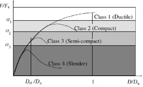
Collapse limit state is related to the actual ultimate strength of the section, evaluated by assuming a distribution of internal stresses accounting for the actual hardening behaviour of material. Cross-sections can be classified according to their capability to reach the above defined limit states, and it can be divided as in Figure 5.
Figure 5: Classification of cross-sections (EN1999-1-1, 2007)
2.1.1.5 Mechanical material properties
According to Annex E in EN 1999-1-1 the analytical characterization of the stress (σ) – strain (ε) relationship of an aluminium alloy can be done by means of one of the following models:
Piecewise models: these models assume that material σ-ε law is described by means of multi linear curve, each branch of it representing the elastic, inelastic and plastic, with or without hardening, region respectively.
Continuous models: These models assume that the material σ-ε law is described by means of a continuous relationship representing the elastic, inelastic and plastic, with or without hardening, region respectively.
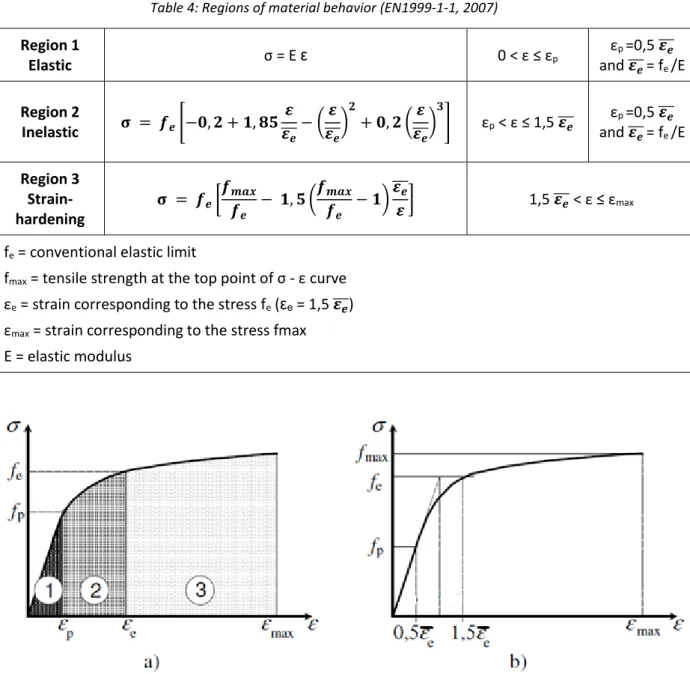
σ= σ(ε) law is assumed, it is convenient to identify three separate regions which can be defined in Figure 6 a) divided for elastic, inelastic and strain-hardening behaviour, respectively.In each region the behaviour of the material is represented by means of different stress vs. strain relationships, which must ensure continuity at their limit points. According to this assumption, the characterization of the stress-strain relationship may be expressed as follows Figure 6 b).
Table 4: Regions of material behavior (EN1999-1-1, 2007) Region 1 Elastic σ = E ε 0 < ε ≤ εp εp =0,5 𝜺̅̅̅𝒆 and 𝜺̅̅̅𝒆= fe /E Region 2 Inelastic 𝛔 = 𝒇𝒆[−𝟎, 𝟐 + 𝟏, 𝟖𝟓 𝜺 𝜺𝒆 ̅̅̅− ( 𝜺 𝜺𝒆 ̅̅̅) 𝟐 + 𝟎, 𝟐 (𝜺 𝜺𝒆 ̅̅̅) 𝟑 ] εp < ε ≤ 1,5 𝜺̅̅̅ 𝒆 and 𝜺εp =0,5 𝜺̅̅̅𝒆 𝒆 ̅̅̅= fe /E Region 3 Strain-hardening 𝛔 = 𝒇𝒆[ 𝒇𝒎𝒂𝒙 𝒇𝒆 − 𝟏, 𝟓 (𝒇𝒎𝒂𝒙 𝒇𝒆 − 𝟏)𝜺̅̅̅𝒆 𝜺] 1,5 𝜺̅̅̅ < ε ≤ ε𝒆 max fe = conventional elastic limit
fmax = tensile strength at the top point of σ - ε curve
εe = strain corresponding to the stress fe (εe = 1,5 𝜺̅̅̅) 𝒆
εmax = strain corresponding to the stress fmax
E = elastic modulus
Figure 6: Continuous models in the form σ = σ(ε) (EN1999-1-1, 2007)
According to experimental data in (EN1999-1-1, 2007) the nominal values of the ultimate strain (εu)
for the several alloys could be calculated using an analytical expression obtained by means of interpolation of available results. This expression, which provides an upper bound limit for the elongation at rupture, can be synthesized by the following expressions:
𝜀𝑢= 0,3 − 0,22
𝑓𝑜(𝑁/𝑚𝑚2)
400 𝑖𝑓 𝑓𝑜< 400 𝑁/𝑚𝑚
Table 5 presents the principal mechanical and physical characteristics of pure aluminium without considering elevated temperature.
Table 5: Mechanical and physical characteristics of pure aluminium
Propriety Observations
Linear thermal expansion coefficient
(α) 23.5 x 10
-6 /oC -
Elastic modulus (E) 70 GPa Until 100 oC
Poison coefficient (υ) 0.33 -
Shear modulus (G) 26 GPa G = E/ [2(1+ υ)]
Yield strength (fyk) ≤ 25 MPa -
Tensile strength (fuk) ≤ 58 MPa -
For European standards based on EN 1999-1-1, Table 3.2 a, b and c mentions the characteristic values of 0.2% proof strength f0, ultimate tensile strength fu for unwelded and HAZ (Heat Affected
Zone) for wrought aluminium alloys. Also, in EN 1999-1-1 Table 3.3 it’s mentioned the characteristic values of 0.2% proof strength f0, ultimate tensile strength fu for cast aluminium alloys – Gravity
castings.
The elasticity modulus or Young’s modulus (E) is the ratio of stress to strain, and for aluminium until 100 °C it’s 70 GPa. Comparing to steel, aluminium presents 3 times lower Young’s modulus, it means most alloys of aluminium dent or scratch more easily as compared to steel. On other side, steel with having a linear thermal expansion coefficient 2 times lower than aluminium, it is less likely to wrap, deform or bend under heat, weight or force.
Aluminium alloys are classified with their specific heat treatment and strength including characteristic values of ultimate tensile strength (fu) and 0.2% proof strength (f0), taking to
consideration the section’s thickness. Table 6 contains some wrought alloys for extruded profiles and its mechanical properties, when all the alloys classification can be found in table 3.2a and 3.2b in (EN1999-1-1, 2007).
Table 6: Alloys and characteristic values (EN1999-1-1, 2007) Alloy EN-AW Temper Thickness (mm) f0 (MPa) fu (MPa) 6060 T5 t ≤ 5 120 160 5 < t ≤ 25 100 140 T6 t ≤ 15 140 170 t ≤ 20 160 215 6063 T5 t ≤ 3 130 175 3 < t ≤ 25 110 160 T6 t ≤ 25 160 195 t ≤ 20 190 220 2.1.1.6 Thermal behaviour
Aluminium like any other metal behaves differently with the rise of temperature, it functions with its normal mechanical characteristic in room temperature, and with elevated temperatures the tensile properties reduces in a relation to temperature and nonuniformly. According to (EN1999-1-2, 2007) and after 2 hours of thermal exposure to elevated temperature, Eal,θ which is Young’s
modulus for all aluminium alloys at elevated temperatures decreases, represented in Figure 7. Aluminium suffers also aluminium elongation during the increasing of temperature.
0 10 20 30 40 50 60 70 80 0 100 200 300 400 500 600 Eal, θ (G Pa) Temperature (°C)
The capacity of transferring or absorbing energy is presented by a physical quantity called the specific heat, and it’s the amount of heat per unit mass required to raise the temperature by one degree Celsius. Aluminium’s specific heat capacity in 20 °C is 911.2 J/ (kg. °C), however it varies with the increasing of the temperature. This relationship is specified in EN 1999-1-2 through the following equation and illustrated in Figure 8.
𝑐𝑎𝑙= 0.41 𝜃𝑎𝑙+ 903 (J/ (kg. °C)) ( 1)
Figure 8: Specific heat of aluminium alloys as a function of the temperature (EN1999-1-2, 2007) The variation of the relative thermal elongation with the temperature determined from the following expression and illustrated in Figure 9. where, ∆l is the temperature induced elongation and l is the length at 20 °C.
∆𝑙/𝑙 = 0.1 𝑥 10−7𝑥 𝜃
𝑎𝑙2 + 22.5 𝑥 10−6 𝑥 𝜃𝑎𝑙 − 4.5 𝑥 10−4 ( 2)
Figure 9: Relative thermal elongation of aluminium alloys as a function of the temperature (EN1999-1-2, 2007)
The mechanical properties of aluminium alloys that have been mentioned before are considered at 20 °C, which is the normal temperature design. In case of fire or a temperature rise, aluminium behaves according to the material temperature, its properties changed such as strength and deformation.
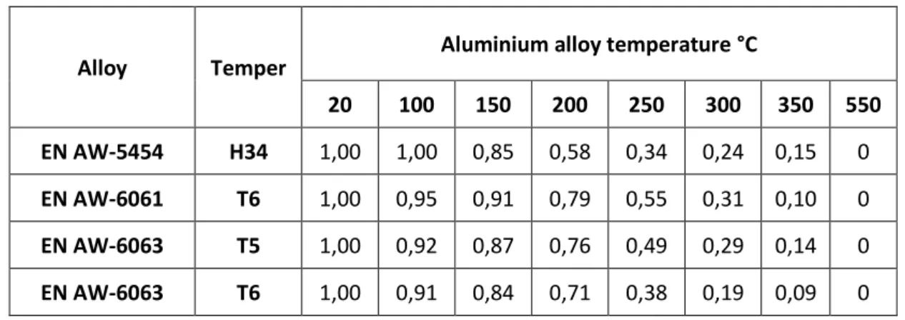
According to (EN1999-1-2, 2007), for thermal exposure up to 2 hours, the 0,2% proof strength at elevated temperature of the aluminium alloys listed in Table 7, follows from:
𝑓𝑜,𝜃 = 𝑘𝑜,𝜃 ∗ 𝑓𝑜 ( 3)
where, fo, θ is 0,2 proof strength at elevated temperature and ko, θ is 0,2 proof strength ratio, its values for some aluminium alloys are listed in Table 1a in EN 1999-1-2, some values with different temperatures is mentioned in Table 7.
Table 7: 0,2% proof strength ratios ko, θ, for aluminium alloys at elevated temperature for up to 2 hours thermal exposure period (EN1999-1-2, 2007)
Alloy Temper Aluminium alloy temperature °C
20 100 150 200 250 300 350 550 EN AW-5454 H34 1,00 1,00 0,85 0,58 0,34 0,24 0,15 0 EN AW-6061 T6 1,00 0,95 0,91 0,79 0,55 0,31 0,10 0 EN AW-6063 T5 1,00 0,92 0,87 0,76 0,49 0,29 0,14 0 EN AW-6063 T6 1,00 0,91 0,84 0,71 0,38 0,19 0,09 0 2.1.1.7 Aluminium contact with other materials
Aluminium has excellent corrosion resistance even in very aggressive environments. This characteristic is from its reaction with oxygen. The contact with oxygen causes the formation of aluminium oxide layer on the surface which works as a protective layer. There are, however, some precautions to be taken in special circumstances which are related with the following cases adapted from Ref. (Camposinhos, 2013).
The electric potential difference, in mV, between aluminium and other metals is variable. Therefore, the contact between aluminium and so-called “electropositive” metals in humid environments may cause the stack effect. So, the contact between aluminium and metals such as
can produce localized harmful effects. Steel screws should be galvanized, but it is always preferable to use screws made of aluminium or stainless-steel alloys.
The presence of gypsum or cement in humid environments, causes a major superficial attack in aluminium leaving white spots that are indelible. These spots do not have any influence on the resistance. While working with gypsum or cement around aluminium windows frames, they must be protected by insulating tapes to avoid the contact.
Most of dry wood has no reaction on aluminium, however, certain woods in the presence of water or humidity react to acidic substances that effect aluminium. It is recommended that wood should be previously painted before its contact with aluminium.
2.1.2 Glass
In architecture and construction, glass has many useful properties such as energy efficiency and acoustic control, glass provide coating to the building that prevent heat escaping through the windows. And the air barrier also enhances acoustic control. It’s also a brittle material with ability to resist deformation under load. Transparency is a property that allow visual connection with the outside world. Its transparency can be permanently altered by adding admixtures to the initial batch mix. By the advent of technology clear glass panels used in buildings can be made opaque (Electro chromatic glazing).
Glass is a fragile material and perfectly elastic, it means that it does not present permanent deformation. The following Table 8 presents some mechanical properties of glass.
Table 8: Mechanical properties – Glass (Savić, 2013)
Density 2.4 Kg/m3
Compressive strength ≥ 69 (Tempered Glass) MPa Flexural strength 120 – 200 (Tempered Glass) MPa
Figure 10: Glass with air barrier in aluminium frame (India business directory, 2019)
The following are glass types that are made with different qualities to enhance their performance adapted from Ref. (Savić, 2013):
Annealed glass is the most commonly used glass, annealing is the process of slowly cooling glass to relieve internal stresses and avoid distortion, this process leads to a good surface flatness for the glass. On the other side this type of glass breaks into sharps which make it dangerous.
Heat-strengthened glass has at least twice the strength and resistance to breakage from wind loads or thermal forces comparing to annealed glass. But like annealed glass it can break into large sharps. Fully tempered glass has at least four times the strength and a breakage resistance of annealed glass, it has been heated and rapidly cooled, increasing its strength and ductility. In breakage scenario, fully tempered glass breaks into small fragments, which makes it suitable as safety glazing under certain conditions like high wind pressure or extreme heat or cold.
Laminated glass is a type of safety glass that holds together when shattered. In the event of breaking, it is held in place by an interlayer, typically of polyvinyl butyral (PVB) between its two or more layers of glass. The interlayer keeps the layers of glass bonded even when broken, and its high strength prevents the glass from breaking up into large sharp pieces. It is a durable and versatile glass with plastic interlayer which provides protection from ultraviolet rays and attenuates vibration and gives laminated glass good acoustical characteristics. Can be used in a variety of environments.
Insulating glass also known as double glazing consists of two or three glass panes separated by an airspace that can be filled during the manufacturing process with either dry air or a low-conductivity gas. The thermal performance of double glazing can be further improved by the addition of a
low-Figure 11: Laminated glass with PVB interlayer
(Glazcon, 2018) Figure 12: Insulated Glass Unit known as IGU (Glazcon, 2018)
Coated glass is covered with reflective or low-emissivity (low-E) coatings. In addition to providing aesthetic appeal, the coatings improve the thermal performance of the glass by reflecting visible light and infrared radiation.
Wired glass is a glass reinforced with rolled steel wires, inserted during the manufacturing of plate glass allowing the glass to adhere together when cracked. It can qualify as safety glass for some applications.
Due to the low thermal conductivity of the glass (0.8 W/ (m. °C)), heating or partial cooling of a glass causes forces within the glass that can cause rupture, called thermal breakage. The most frequent thermal breakage occurs when the edges of a glass which is contained within the frame experiences a thermal exposure causing slower heating than the surface of the glass.
2.1.3 Steel
Steel is an alloy consisting mainly of iron with an addition of carbon content varies between 2.0 – 2.1 % of its weight. Adding carbon to iron increases its strength. This variety of properties such as toughness, ductility, weldability, durability, recyclability gives steel a wide spectrum of uses. Steel is used in many ways in an aluminium façade, taking advantage of its strength, its resistance to fire. Steel Brackets are used to support aluminium modules, fixing the elements of the façade and transfer the façade weight to the slab. Brackets can take many shapes based on the condition of installation.
2.1.3.1 Structural steel properties
Structural steel differs from concrete in its attributed compressive strength as well as tensile strength. For properties like, having high strength, stiffness, toughness, and ductile properties, structural steel is one of the most commonly used materials in commercial and industrial building construction.
Structural steel can be developed into nearly any shape, which are either bolted or welded together in construction. It can be erected as soon as the materials are delivered on site, making steel a schedule-friendly construction material.
Steel is inherently a noncombustible material. However, with temperature rise in a fire scenario, the strength and stiffness of the material is significantly reduced. The International Building Code requires steel be enveloped in sufficient fire-resistant materials.
Structural steel is mechanically classified according to EN 1993-1-1 (Table 3.1) by the nominal value of yield strength fy and the ultimate strength fu, based on the manufacturing process, standards,
type of steel alloy and thickness. The designation of steel starts with the letter S for Steel, then it’s followed by number that represents its yield strength, like S235.
Table 9: Design values for Structural steel Coefficients (EN1993-1-2, 2005)
Elasticity modulus – E 210 GPa
Shear modulus – G 81 GPa
Poisson ratio in elastic stage - υ 0.3
Linear thermal expansion coefficient - α 12 x 10-6 Per K (for T≤100 °C)
Specific heat capacity for steel varies with temperature rise, however, in 1995 edition of EN 1993-1-2 and for simplified calculations, Cs can be considered 600 J/(kg.K) independently of steel’s
temperature (Vila Real, Incêndio em Estruturas Metálicas, 2003).
𝑐𝑠= { 425 + 7.73 𝑥 10−1𝑥 𝜃𝑠 − 1.69 𝑥 10−3𝑥 𝜃𝑠2 + 2.22 𝑥 10−6𝑥 𝜃𝑠3 𝑓𝑜𝑟 20℃ ≤ 𝜃𝑠 < 600℃ 666 + 13002 738 − 𝜃𝑠 𝑓𝑜𝑟 600℃ ≤ 𝜃𝑠 < 735℃ 545 +𝜃17820 𝑠−731 𝑓𝑜𝑟 735℃ ≤ 𝜃𝑠 < 900℃ (𝐽/𝑘𝑔𝐾) ( 4)
Figure 13: Specific heat capacity of Structural steel as a function of the temperature (EN1993-1-2, 2005) Thermal conductivity of Steel is also given in EN 1993-1-2 as a function of steel temperature, for temperatures between 20℃ and 800℃ λs equals to 54 − 3.33 𝑥 10−2𝑥 𝜃𝑠 (W/(m.K)), and for
temperatures between 800℃ and 1200℃, the value is 27.3 (W/(m.K)).
Relative thermal elongation of Structural steel is also a function of steel temperature according to EN 1993-1-2, given in the following expression, where l is the element initial length in 20 °C.
∆𝑙/𝑙 = { 1.2 𝑥 10−5𝑥 𝜃 𝑠 + 0.4 𝑥 10−8𝑥 𝜃𝑠2 − 2.416 𝑥 10−4 𝑓𝑜𝑟 20℃ ≤ 𝜃𝑠 < 750℃ 1.1 𝑥 10−2 𝑓𝑜𝑟 750℃ ≤ 𝜃 𝑠 < 860℃ 2 𝑥 10−5𝑥 𝜃 𝑠 − 6.2 𝑥 10−3 𝑓𝑜𝑟 860℃ ≤ 𝜃𝑠 < 1200℃ ( 5)
2.1.3.2 Steel bracket
Steel brackets in façades are supporting members attached to the slab to transfer the module loads to it. It takes several shapes depend on the conditions of installing and its required resistance. Brackets are connected to the body of the module by string of weld or bolts through screw holes in a galvanized steel sheet that support the rest of the module members. The connection with the slab is done by bolts attached to the Cast-in Channel.
Cast-in Channel system is a fixing system consists of rolled steel elements that are cast into concrete structure, provided with bolts designed to hold the module through its bracket. Cast-in channel are installed during the structure execution phase. Advantages like, high load capacity, fixing without damaging concrete, the easy installation and the absence of drilling make this system a useful and a common solution for façades projects.
Figure 15: Cast-in Channel connected to the reinforcement (©Hilti, 2019)
2.1.3.3 Galvanized Steel Sheet
Galvanizing is a zinc coating applied to steel sheets, a process in which steel sheet passes in a bath of molten zinc. The bond between liquid zinc and iron in steel forms a protective layer. The finished product resists corrosion without any additional painting or coating making galvanized steel sheet the most economical process to protect steel from corrosion (Hornbacher, 2019).
2.1.4 Glass Reinforced Concrete – GRC
GRC is composite material, consists of mixing cement and sand reinforced with glass fibers. It is commonly used in cladding of modern façades. Its light weight makes it one of the best solutions for reducing dead load on the building and its density is between 1.9-2.1 ton per m3 (Spray up GRC).
The design of GRC panels uses a knowledge of its basic properties under tensile, compressive, bending and shear forces, coupled with estimates of behavior under secondary loading effects such as thermal response and water infiltration.
Spray is one of the manufacturing methods of GRC, starts with high shear mixing of water and admixture (and polymer if used), then sand/cement slowly added to the mixture until a smooth creamy slurry is achieved by reaching to a specific consistency. After that the mixture is transferred to a pump provided with a spray gun to be projected to a mold surface using an air supply from a compressor. Some mixtures need 7 days of curing after projecting. if a polymer curing compound is used in the mixture, the units can be exposed to the atmosphere immediately although it is advisable to keep them protected from direct sunlight or external conditions for a day or two. Premix is another manufacturing method of GRC, where sand/cement and glass fibers are pre-mixed. The production using this method can involve several technics like injection or vibration. When the mixture is ready, it’s poured into mold which is vibrated to liberate air from inside the mixture.
The curing of these composites should be done by a wet process in which the pieces after demolding are introduced into a steam oven or by the introduction of polymers into the blend.
Table 10: GRC - Mechanical properties (WikiMartifer, 2019) Properties Spray up Premix
Density 1.9 – 2.1 1.8 – 2.0 t/m3 Compressive
strength 50 – 80 40 – 60 MPa
Elasticity modulus 10 – 20 GPa
In terms of thermal function, GRC’s thermal conductivity coefficient varies between 0.5 and 1.0 W/(m.°C), and this physical property makes GRC a good thermal insulation. It also provides the building with acoustic insulation, for a panel of GRC with 10mm thickness there will be an acoustic reduction of 20 to 30 dB (WikiMartifer, 2019).
Figure 17: Spraying process (WikiMartifer, 2019)
Figure 18: Premix process (WikiMartifer, 2019)
2.2
Types of façades
Technological developments have completely changed the concept of façades. Until very recently the façade only represented a separation between the exterior and the interior. Now, it acts as an active module that will have to interact in the best way with extreme climatic conditions, with the effect of transparency, ventilation, heat and noise pollution.
The following types of façades are the type of façades designed, developed and fabricated in Martifer Alumínios different projects. The following mentioned façade’s definitions and characteristics are adapted from Ref. (WikiMartifer, 2019).
2.2.1 Curtain wall
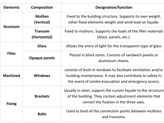
The curtain façade consists of an aluminum and glass system integrated in the new architecture concepts for buildings. This system guarantees the specific functionalities of the project in structural terms and of air permeability, water tightness and mechanical resistance to the wind action. The composition of the curtain wall system includes resistant elements, filler elements, machined
Table 11: Composition of curtain wall (WikiMartifer, 2019)
Elements Composition Designation/function
Resistant
Mullion (Vertical)
Fixed to the building structure. Supports its own weight, other fixed elements weight and wind load on façade. Transom
(Horizontal)
Fixed to mullions. Supports the loads of the filler materials (Glass, panels, etc.).
Filler
Glass Allows the entry of light for the transparent type of glass Opaque panels Placed in blind zones. Consists of sandwich panels or
aluminium sheets.
Machined Windows
consists of built-in windows to facilitate ventilation and/or building maintenance. It may also contribute to safety in
the event of smoke evacuation and emergency access.
Fixing
Brackets
Usually in steel, support the curtain façade to the structure of the building. They contain adjustment elements that
correct the fixation in the three axes.
Bolts Used to bind all the connection points between mullions and transoms.
Curtain walls can be classified structurally according the construction system, it can be continuous, when the façade passes in front of the slab or interrupted, when it is between the slabs.
Figure 19: Continuous curtain wall (WikiMartifer, 2019)
Figure 20: interrupted curtain wall (WikiMartifer, 2019)
In terms of installation curtain walls can be modular, traditional and semi-modular. Modular systems or framed systems are fabricated in finished modules including the filling of glass, windows, doors and buckling parts to install in the site. Each module in these systems are structurally independent of the remaining modules, and its height coincides with the distance between the slabs. Traditional systems are fabricated from mullions, transoms and other fixation members installed in the site. Semi-modular systems are a combination of the two previous types of systems. 2.2.1.1 Modular façade (Unitized system)
Modular façade is formed by modular units contains all the necessary components for its manufacturing and installation. The fixing notches are incorporated into the perimeter, ensuring ease of handling during transport and offloading at the site. During manufacturing phase these units are produced with a quality that can be strictly controlled. The installation process requires less time than the traditional type of façades, where units have to be lifted by crane to be fixed in its position which is more efficient than scaffolding.
Advantages • Flexibility
• Don’t require scaffolding
• High quality of assembly in factory • Effective watertight between the units • Supports larger joint movements Disadvantages
• Requires a specialized manpower • Elevated costs
Figure 21: The Installation of modular façade (©Martifer, 2019)
2.2.1.2 Traditional façades (Stick system)
The traditional curtain façades result from the combination of glass panels with aluminium members visible from outside, where the vertical and horizontal members are well defined. In this system the glazing is performed by back cape that fix the glass to the supporting structure. The clamping cap (vertical and horizontal) is protected by an outer cape, fixed by clipping. The outer shells and the clamping shells are insulated from the glass through an EPDM insulation profile (outer seals) as well as the inner frame (inner seals). This is made up of aluminum profiles that form the uprights and has drainage and ventilation channels that guarantee, together with the EPDM joints system, the weathertightness and permeability of the System.
Advantages
• Common solution • Low cost
• Fast execution at the site • Ease delivery for extra members Disadvantages
• The need for scaffolding • Elevated assembly duration
• Difficult quality control for assembly • The need for storage at the site • Outsider fixing for glass
Figure 22: Traditional façade system (WikiMartifer, 2019)
2.2.1.3 Façade type Aufsat
Aufsat façade varies from other types of façades where mullions and transoms are not aluminium members. The auxiliary structure’s members are mostly steel or wood, and their combination with aluminium enables a range of unique solutions both aesthetically and technically.
2.2.1.4 Façade type VEC
This system replaces the exterior aluminum profiles with structural silicone with high adhesion that attaches glass to interior aluminium profiles. Structural silicone is responsible for transmitting loads to the aluminium structure. In order to guarantee the protection and safety of the glasses, additional support pieces are placed in the fixing system. This system results a reduction of the façade load and an aesthetic effect with a transparent façade and glass as a main element. The manufacturing process of this type of systems includes restricted control measurements as well as maintenance during its service phase, problems of aging, surface cleaning and water tightness are fundamental points that must be addressed and considered.
Figure 23: Aufsat façade; Aluminium - Wood
(WikiMartifer, 2019) Figure 24: Façade VEC (Navarra, 2018).
2.2.2 Ventilated façade systems
This type of façades consists of exterior coating system separated from the main structure creating air barrier, allowing a natural and continuous ventilation. This effect called chimney effect when air enters cold from the inferior, circulate and leaves heated from the superior.
The main advantages of ventilated façade are avoiding humidity and condensation, contributing to energy savings and reducing the risk of early degradation of materials giving the building a higher quality and thermal comfort. The fixing system is the supporting structure which consists of vertical and horizontal members, generally aluminium or stainless steel. The exterior material used, can be Ceramics, stone or glass.
Figure 25: Chimney effect (WikiMartifer, 2019)
The glazed ventilated façade, also called double skin façade, consists of two curtain walls, that is, a curtain façade on the outside and another on the inside. This system consists of double-glazing support on the inner cloth, followed by an air chamber and a single glass placed on the outer face of the support profiles. It may also include a shutter or other elements in the air chamber. The objectives of a double glass façade refer to the visualization of the external environment of the building, access to natural light, improvement of acoustic conditions, natural ventilation of the interior of the building, reduction of energy consumption with cooling or caulking, among others. The most common system for the application of a ventilated façade in ceramic is composed of a support profile that is fixed to the wall panel duly insulated from the outside. The panels are subsequently coupled to metal member fittings.
Now a day’s architecture shows an increasing interest in the façades ventilated with stone, an application of high aesthetic value and with unparalleled thermal insulation capability. In this type of coating, the joints are almost always in top and they don’t provide water tightness. These panels may only be watertight if the fixing system make them independent of the wall and if the air barrier formed between the coating and the support is vented. The maximum size of the stone shall not exceed 1.40 m, the building’s height shall be less than 28 m and the maximum surface of the stone shall not exceed 1 m2.
The principal’s advantages of a ventilated façade system are energy saving by having an excellent thermal insulation, protection against humidity by being watertight and environment friendly.
3
London Dock building C1 Project
3.1
Architecture
The ongoing project in Martifer Alumínios Building C1 – London Dock located in Gauging square, London, UK. It’s a residential story tower with 27 floors above ground and 96.39m height. Designed by architect Patel Taylor and developed by St. George.
Throughout the project Martifer Alumínios is responsible for designing, manufacturing and assembling of approximately 7500 m2 of unitized curtain wall, 2450 m2 of stick system, 700 m2 of
glass fins, 600 m2 of stone, 250 m2 of canopies and balconies.
Figure 27: St George, London Dock, Building C1 (Berkeley, 2019)
West and east elevations in Figure 28 a) and b) are composed of unitized façade system which is a modular curtain wall with units consists of fixed glazing, opaque panels, windows and doors. In addition to that east elevation is provided with cladding of GRC, this solution will provide a thermal insulation, weather resistance and improve the appearance of the building. Behind the GRC panels the modular unit is finished with aluminium sheet of 3mm thickness.
North and south elevations in Figure 28 c) and d) are mostly composed of balconies with stick façade system which is a traditional curtain wall where aluminium mullions and transoms are assembled in site with the rest of the filler material, and balconies platforms are provided by another subcontractor.
a) b)
Figure 29: Typical floor Plan - London Dock Building C1 (©Martifer, 2019)
The unitized façade system has two types, West façade Figure 28 a) is designed with a capless aluminium modules where glass is fixed with structural silicone exteriorly with the interior aluminium profiles creating a structural joint of 22mm between every module. East façade Figure 28 b) is designed with a capped structural joint between modules where glass is fixed to the interior aluminium profiles by an exterior aluminium members.
3.2
Façade preparation
The façade preparation for London Dock Building C1 is one of the duties of Martifer Alumínios to design, fabricate and install at the site, involves several functions and activities that aim to develop the approved solutions for application on site. During all the phases of preparation there are activities to be carried out by the team responsible of the work and, in this sense, this subchapter exposes these works executed and how these relate to all other specialties and departments parallel to the project.
Computer’s software assists and accelerates the process of preparation. One of the main programs used in this job is AutoCAD through sheet set mode where all the related drawings are available in a shared network with their layouts, all contains external references for the project details to make it easier for major modifications. AutoCAD allows the creation of manufacturing plans and approval
drawings , organization of plans and details, and all other particularities of the work related to drawing.
Other computer tools, both for the preparation of frames and for the manufacturing plans of sheets, are FPpro, PlanIQ and AlphaCAM, which are software that allows the creation of a digital model in order to obtain optimizations of materials, machining rates, construction methods and 3D visualizations that allow a better perception of the final product, in this aspect, also aided by the SolidWorks program.
For the management and logistics of all resources related to the work, materials and humans, IMS and SAP programs are used to consult available material, face-to-face punching and workmanship at the manufacturing level.
3.2.1 Design phase
Martifer’s Design team provides the clients with constructive solutions for the façade and the cladding system of the building, then the chosen solution should be approved. Every structural or non-structural member must be designed and sized, all the calculation of profiles considering loads and combination that represent physical condition of the construction must be approved before starting the manufacturing process. Materials also must be chosen and approved after computer simulations that describe the material behaviour, obtained by a third party in thermal and acoustic issues for instance.
All the design details with its own calculation is in a series of documents submitted from Martifer Alumínios to client with a specific time schedule to be approved.
3.2.2 Approval phase
An approval drawing is a drawing in which the proposed solutions are transmitted to the client in accordance with the project specifications. These drawings are evaluated by the customer, subsequently require approval with the classification "A" (Approved), "B" (Approved, needs minor modifications) or "C" (Disapproved). Only those drawings classified as "A" are considered to be approved and, when the classification is "B" or "C", the drawings are subject to a new approval, once corrected. Any major modification has to be calculated and approved by the design team first,
When any doubt arises regarding the specifications required by the client or architecture, documents are prepared that address the resolution of a specific urgency problem. These documents, called "RFI's", consist of the exposure of the doubt or inaccuracy in question and attached files that help to better understand the problem. This process of communication between companies is carried out by a digital platform called "ACONEX", which assists the management of documents.
Figure 30: Approval drawing of a modular unit details (©Martifer, 2019)
3.2.3 Manufacturing phase
A manufacturing plan (PF) is a set of drawings that contain the information necessary for the manufacture of a particular module, sheet, frame or part of the work. Usually, their realization is intended to indicate measures, notches or specific connections, machining of profiles or plates, sheet bending, drainage, details and detailed information of all the materials.
The process of drawing up a PF initially begins in AutoCAD. Subsequently, depending on the type of PF, a model is created through specific computer software, which allows to obtain the best optimization of the material, machining rates and a cutting list, which informs the factory worker the correct way to proceed. cutting of the raw materials, whether they are sheets or profiles. For example, in case of cutting a sheet, optimization will help choose the right size of sheets to cut for
less material waste. Computer software also helps with making a time frame for executing and manufacturing the requested job.
After all this informative and auxiliary work has been prepared, the logistics part of the PF is made, listing the available material required for the manufacture of the PF. If any material required for the manufacturing plan is missing, it is possible to transfer material from a subcontractor. This entire process is aided by software Plan IQ, IMS and SAP, which allow better management of company resources. The approval of all the jobs have been prepared is from the factory responsible, by approving PF, it will be sent to the factory to start its manufacturing phase.
One of the frequent manufacturing plans are galvanized steel sheet plans, and producing these plans includes a series of tasks starting by designing in AutoCAD the requested sheets with their specific dimensions in a flattened state, marking the cut and folding zones, provide the sheet with requested screw holes and prepare a self-control sheet for the sheets to be labored in the factory. Each sheet will be referenced with its dimensions and quantity in a management document called Job Summery. The necessary material in this job has be shipped and stored, for that a shipping list and a list of requirements have to be issued to inform the purchasing team and quantify the required materials.
The production of flat aluminium sheets with screw holes in Martifer’s factory is made by a CNC (Computer Numerical Control) machine that can identify with the assistance of AlphaCAM computer software the positions of holes in the sheet by identifying the design lines and their layers in AutoCAD. Using the CNC machine increases the job efficiency by saving time, providing a higher secure working conditions and decreasing the errors range.
3.2.4 Installation phase
Cast-in channel system has been installed all over the slab edges during the structural execution, and the installation phase starts with the installation of the brackets. For that the edges of the slab must be protected by a safety system and safety net, because of the high risk of falling in this activity.
After making sure that cast-in channel is properly cleaned, T bolts will be inserted on the bracket and rotated to ensure that it is prefixed to the Cast-In insert channel. The bolt mark must be perpendicular to Cast In. Brackets must be fixed according to their tolerances and the bolts are tightened to the correct torque.
4
Fire resistance of aluminium mullion
This chapter will elaborate in the fire design of a mullion in a specific aluminium module from the project London Dock Building C1 mentioned in chapter 3.
Figure 33: Module – 3D (©Martifer, 2019)
The studied module is composed of two opaque panels closed from the internal surface by two galvanized steel sheets and filled with mineral wool in between those two. All of these filler materials are fixed to aluminium transom, then the last one is fixed to mullion. The module is manufactured and assembled in the factory to be ready for installation in site.
Figure 35: The studied mullion – Detail (©Martifer, 2019)
The studied section Figure 36 is painted with color RAL9004, and the following Table 12 contains the geometrical and mechanical properties of it. The information in Table 12 is according to the designing document of aluminium profiles in London Dock building C1 project.
Table 12: Mullion - technical sheet Alloy EN AW-6063 T6 fo 160 MPa fu 195 MPa Buckling Class A Area 1484 mm2 Ix 289.9 cm4 Iy 261.44 cm4 Wx 46.42 cm3 Wy 46.51 cm3 Cross-section Class 4 Aeff 1351 mm2 Ix,eff 322.67 cm4 Iy,eff 238.6 cm4 wx,eff 36.12 cm3 wy,eff 42.31 cm3
4.1
Fire action
A fire scenario is a description of the course of a fire with time identifying key events that characterise it and differentiate it from other possible fires. It defines the fire growth process; the fully developed stage includes the building environment and systems that will impact on the course of the fire (F. Wald, 2008).
One of the consequences of a fire action is the indirect internal forces and moments caused by thermal expansion in constructive and structural elements. The first step of quantifying the action would be define the relation between time and temperature represent the fully developed fire in a compartment.