RESEARCH NOTE
Sphere-plane methodology to evaluate
the wear of titanium of dental implants:
a research proposal
Teresa Almeida Mendes
1*, João Caramês
1, Luís Pires Lopes
1and Amílcar Lopes Ramalho
2Abstract
Objective: Titanium is the most commonly used material to manufacture dental implants and abutments. Recently,
zirconia abutments have been manufactured with better aesthetic properties. However, zirconia abutments are harder than titanium implants; therefore, they could wear the implant surface. Therefore, this article aims to describe a sphere-plane system that can be used to assess the wear that different abutment materials cause in the titanium of dental implants when submitted to cyclic loading. This method can be used to simulate the oral cavity, where the abutment (sphere) applies loads onto the implant (titanium plane). The spheres were made of different materials (titanium and zirconia), and the specimens were loaded for 4,000,000 cycles. The scar size and area on titanium planes were measured with stereoscopic images and analysed through profilometry.
Results: The wear of titanium planes was similar when tested against zirconia or titanium spheres. The
sphere-plane system is a method that can be used to evaluate and quantify the wear of the titanium of dental implants, and compared with methods that use real implants, this system is simpler and less expensive. This method could facilitate further research to evaluate the wear of titanium against different materials and under different testing conditions.
Keywords: Dental implants, Wear, Radial fretting, Abutment, Titanium, Zirconia
© The Author(s) 2018. This article is distributed under the terms of the Creative Commons Attribution 4.0 International License (http://creat iveco mmons .org/licen ses/by/4.0/), which permits unrestricted use, distribution, and reproduction in any medium, provided you give appropriate credit to the original author(s) and the source, provide a link to the Creative Commons license, and indicate if changes were made. The Creative Commons Public Domain Dedication waiver (http://creat iveco mmons .org/ publi cdoma in/zero/1.0/) applies to the data made available in this article, unless otherwise stated.
Introduction
The most commonly used material to manufacture implants and abutments is titanium [1]. Titanium is a biocompatible material [2] with a low risk of corrosion [3]. However, titanium abutments can change the appear-ance of soft tissues, thereby compromising aesthetics [4, 5].
To overcome this limitation, zirconia abutments were manufactured (polycrystalline tetragonal zirconium oxide, stabilized with 3-yttrium) [6]. Since the intro-duction of zirconia abutments, the interest in them has greatly increased due to their aesthetic properties and high mechanical strength [2]. However, according to sev-eral authors, zirconia abutments could be more prone to fracture [7] and have less marginal accuracy [8] than
titanium abutments. As zirconia is 10 times harder than titanium [2], it could cause wear on the implant surface over time [9, 10]. This phenomenon is called fretting wear and can compromise the long-term stability of the implant-abutment connection [10].
Radial fretting wear is caused by the relative oscilla-tory movement of small amplitudes, which may occur between two surfaces that remain in contact [11] and is primarily induced by varying the normal load [12]. In radial fretting, the cyclic load is applied to a Hertzian contact, resulting in a cyclic increase and decrease of the contact area. The morphology of the contact surface dis-plays wear in an annular region, which corresponds to a region of slip between the two materials in contact [13].
This technique can be used to simulate the implant abutment’s contact with a sphere-plane system, where the sphere simulates the abutment and the plane simu-lates the implant. As in the implant-abutment surface, in the sphere-plane system, the surfaces remain in con-tact, and the relative oscillatory movement has a small
Open Access
*Correspondence: [email protected]
1 Faculdade de Medicina Dentária, Universidade de Lisboa, Cidade
Universitária, 1649-003 Lisbon, Portugal
amplitude. Micromotion at the implant-abutment inter-face ranged from 1.52 to 94.00 μm at the external contact [14]; in the internal contact, it varied between 0.20 and 5.67 μm [15] with different types of implant-abutment connections (external and internal).
The geometry of a real implant-abutment connec-tion is complex, making it difficult to obtain data from the implant to measure the wear [9]. To the best of our knowledge, only one study [9] described data from the wear in a dental implant at the implant-abutment connec-tion using a very complex and expensive methodology. The objective of this article is to describe a new method that uses a sphere-plane system with simple geometry to measure the wear and fatigue phenomena that different abutment materials can cause in the titanium of dental implants when submitted to cyclic loading.
Main text
Methods
This in vitro study used a sphere-plane contact. The spheres applied cyclic loads on titanium planes in a mechanically actuated contact fatigue and radial fretting test machine. This setup was used with the intention of simulating oral cavity use, where the abutment (sphere) transfers the masticatory forces to the dental implant (plane).
Materials
The planes were made of commercially pure titanium grade 4 (ASTM F67) [16]. Titanium grade 4 has the high-est strength of all of the unalloyed ASTM pure titanium grades [17] and is considered the material of choice for intra-osseous use in the medical field [18]. Titanium grade 4 is less toxic than titanium alloys and has a low allergenic potential and an excellent corrosion resistance [18]. The minimization of ion release contributes to the biocompatibility of this material [2].
Two different sphere materials were tested to simulate implant abutments, forming two different groups: tita-nium grade 5 (control group) and zirconia [6] (experi-mental group). The material most commonly used to manufacture restorative abutments is titanium grade
5 (Ti-6Al-4V), since this alloy has higher hardness and fatigue resistance in comparison with pure titanium [17].
Titanium planes were polished following the regimen recommended for metallographic polishing [19, 20].
Testing conditions and cyclic load
The testing machine was a tribological system with mechanically actuated contact fatigue and radial fretting built at the Department of Mechanical Engineering, Uni-versity of Coimbra. A relative displacement was gener-ated between the spherical specimen placed on the top (sphere vertical support) and the flat specimen (horizon-tal) in accordance with the flexible vibration of the elec-tric motor (Additional file 1).
For each group, tests were performed under two differ-ent simulation environmdiffer-ents: air and artificial saliva [21]. The test performed in air was used to control the influ-ence of artificial saliva (SAGF medium), which enables the in vitro reproduction and the study of many physico-chemical phenomena that can develop in the mouth. It has a complete composition closer to human saliva than other means of simpler artificial saliva [21].
The artificial saliva was applied twice a day (12 h of interval) to the interface of the plane-sphere with a PVC tube with a diameter of 4.2 cm. The SAGF pH was checked every day (Inolab WTW) to determine if they were stable.
The specimens were submitted to a 20 N load (peak to peak) with a 15 Hz frequency for 4,000,000 cycles with a sphere measuring 10 mm in diameter. Table 1 presents the four samples that were tested and the testing condi-tions that were met, with one specimen being tested in each testing condition.
Area loss and scar measurement
The geometry of the planes with damaged contact areas was measured with a laser profilometry microtopog-rapher (Mahr, Germany). The data obtained from the microtopographer was analysed with Gwyddion (Czech Metrology Institute), a modular program for data visuali-zation and analysis, and the two-dimensional (2D) pro-files of the scars were extracted. The concavities on the edges of the scars (wear zones) were further analysed with Microsoft Excel with the tool Curve integration Macro to determine the removed area by calculating the area on the concave zone of the scar.
Additionally, images of the scars on planes were obtained with the stereoscopic microscope (Nikon Stereophoto SMZ-10) and analysed with ImageJ soft-ware (National Institutes for Health) to measure the outer diameter. Five measures were obtained for each specimen.
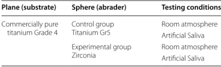
Table 1 Samples tested
Plane (substrate) Sphere (abrader) Testing conditions
Commercially pure
titanium Grade 4 Control groupTitanium Gr5 Room atmosphereArtificial Saliva Experimental group
Scanning electron microscope (SEM) images
SEM images of the scars on planes were obtained with low and high magnification (Philips XL series 30).
Hertzian diameter
The contact diameter between the plane and sphere can be calculated as the Hertzian diameter. The following for-mula is used for the calculation:
Formula 1—Hertzian diameter P represents the normal force; Req is the reduced radius, and E is the reduced Young’s modulus of the materials.
Results
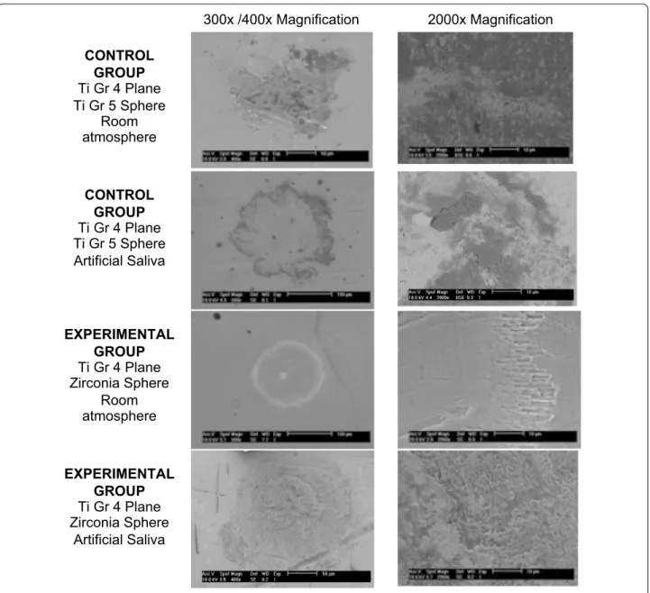
Stereoscope images of titanium plane scars
Representative SEM images of titanium plane scars are depicted in Fig. 1. The configuration of the fretting wear scars left on the planes is similar to a ring in a top view. With the zirconia sphere at room temperature, the ring scar is the most perfect. On the test performed with arti-ficial saliva in SEM images at high magnification, we can see that the ring surface is highly irregular and dense.
Area loss on titanium planes
The material area loss was low on the control and experi-mental groups, with the area of loss between 0.10 and 0.03 µm2 on the test performed with titanium–titanium contact at room temperature and in contact with artifi-cial saliva, respectively. Regardless of the material used in the sphere, the amount of area loss was lower in the pres-ence of artificial saliva.
Diameter of the scars on titanium planes
The graphs in Fig. 2 represents the outer diameter of the scars measured on titanium planes. The outer diameter was similar in control and experimental groups. At room temperature, the outer diameter was slightly higher than that of the tests performed under artificial saliva.
Hertzian diameter
The contact diameter between the plane and sphere var-ied between 0.13 and 0.23 mm.
Discussion
The primary conclusion of this article is that the pro-posed technique is an alternative for the evaluation of wear on dental implants. It was possible to observe and to measure the wear, which was different according to the antagonist surfaces (zirconia and titanium) and the
α=
3PReq
4E∗
13
presence and absence of saliva, which means that this method enables the evaluation of different variables (material, presence of saliva).
It can be observed that the tests performed with arti-ficial saliva had smaller scars. The reduction in wear can be explained by the fact that the presence of saliva creates a corrosive environment, which leads to oxide forma-tion that increases the fricforma-tion coefficient, thus decreas-ing wear [22]. The scars produced on titanium planes had small differences in diameter and area of loss, both with zirconia (experimental group) and titanium (control group) spheres.
When assessing the obtained data in the 2D profile, it was possible to observe that wear occurs only on the ring corresponding to the slip zone and the inner part of the ring remains almost intact, corresponding to a stick zone. The contact centre is in compression all the time (stick-ing) and the micro-slip occurs at the contact edge. This displacement field confirms the existence of radial fret-ting that always runs in partial slip contact [13].
According to the results of this test, the expected area of loss on titanium planes that simulate dental implants will be under 0.1 µm2. These planes require accurate image acquisition and data analysis tools. The inter-nal geometry of a dental implant is complex due to the indexations that are intended to create anti-rotational resistance and serve as a reference for the positioning of the prosthetic abutment. The implant-abutment con-nections can be divided into two major groups: external and internal connections. The internal connections were introduced more recently. The connections are character-ized by the presence of the connection mechanism inside the implant body [23]. Internal connections have a supe-rior contact area and lower micromovements between implant and abutment [24]. These movements may cause wear of dental implants [10], which may be lower on internal connections. Further studies are needed to increase the knowledge of these phenomena.
The geometry of internal connections is challenging to observe. In electron microscopy, the interior of the implants appears as a deep, unfocused dark cavity. Even in optical 3D surface metrology (Alicona, Austria) cou-pled with light devices, the images obtained have many imperfections due to the light reflection from the metal of the implant.
Recent studies measured the implant abutment sys-tem by longitudinal cross-sections after embedding the system in epoxy resin. A mechanical means of section-ing and polishsection-ing to enable direct visualization of the implant-abutment interface can produce significant deformation on the surface of the specimen, smear-ing the materials and polishsmear-ing residue into the spaces between the components [25].
The force selected for this test was 20 N to prevent the plastic deformation that can occur between the con-tact surfaces when submitted to stronger forces, thereby removing the radial fretting [11]. The contact diameter between the plane and sphere (Hertzian diameter) was 0.13 to 0.23 mm. An implant with a regular platform is 4.1 mm in diameter; therefore, the contact between the implant and the abutment has that diameter, which is greater than the diameter of the sphere-plane contact. In the mouth, there are forces superior to 20 N [26], but the diameter of contact between the surfaces is greater. 300x /400x Magnification 2000x Magnification CONTROL GROUP Ti Gr 4 Plane Ti Gr 5 Sphere Room atmosphere CONTROL GROUP Ti Gr 4 Plane Ti Gr 5 Sphere Artificial Saliva EXPERIMENTAL GROUP Ti Gr 4 Plane Zirconia Sphere Room atmosphere EXPERIMENTAL GROUP Ti Gr 4 Plane Zirconia Sphere Artificial Saliva
Fig. 1 SEM images of titanium grade 4 plane scars
Fig. 2 Results of average and standard deviation of the outer
Conclusions
The sphere-plane system enables the simulation of the dental implant-abutment contact. This system is an alternative method for the evaluation of wear on dental implants that is simpler and less expensive than the meth-ods that use real implants. The implant is represented by the plane with simple geometry, enabling accurate meas-urement of the wear with profilometry techniques and SEM images. With this method, it is possible to evaluate the wear with different abutment materials and different testing environments, including artificial saliva.
Limitations
Further tests should be improved with a greater sphere diameter to create larger scars on titanium planes to be easily measured with 3D profilometry and measure the volume of loss.
As an in vitro study, these conditions were a simulation of the oral environment. Further microscopy techniques should be developed by microscope manufacturers to improve the measurements of the real geometry with dif-ferent implant connections.
Additional file
Additional file 1: Figure S1. Schematic representation of the testing machine and correspondence between the sphere-plane system and implant-abutment system. This figure contains a schematic representation of the testing machine used on the article. It also shows the correspond-ence between the sphere and a prosthetic abutment, and between the plane and a dental implant.
Authors’ contributions
TAM, ALR and LPL conceived of the project. TAM and ALR collected the data and conducted the data analysis with support from LPL. JC Participated in data interpretation and reviewed the draft manuscript. All authors were involved in drafting the manuscript. All authors read and approved the final manuscript.
Author details
1 Faculdade de Medicina Dentária, Universidade de Lisboa, Cidade
Univer-sitária, 1649-003 Lisbon, Portugal. 2 CEMMPRE, Department of Mechanical
Engineering, University of Coimbra, Rua Luís Reis Santos, 3030-788 Coimbra, Portugal.
Acknowledgements
We would like to thank Professor João Silveira for his contribution to produc-ing the artificial saliva and Eng. André Portugal Santos for his help in operatproduc-ing the testing machines.
Competing interests
The authors declare that they have no competing interests.
Availability of data and materials
The datasets analysed in the current study are available from the correspond-ing author on request.
Consent for publication
Not applicable.
Ethical approval and consent to participate
Not applicable.
Funding
This research did not receive any specific grant from funding agencies in the public, commercial or non-for-profit sectors.
Publisher’s Note
Springer Nature remains neutral with regard to jurisdictional claims in pub-lished maps and institutional affiliations.
Received: 23 May 2018 Accepted: 21 July 2018
References
1. Baixe S, Fauxpoint G, Arntz Y, Etienne O. Microgap between zirconia abutments and titanium implants. Int J Oral Maxillofac Implants. 2010;25(3):455–60.
2. Anusavice K, Shen C, Rawls R. Phillips’ science of dental materials. 12th ed. Amsterdam: Saunders Elsevier; 2012.
3. Sierraalta M, Vivas JL, Razzoog ME, Wang RF. Precision of fit of titanium and cast implant frameworks using a new matching formula. Int J Dent. 2012;2012:374315. https ://doi.org/10.1155/2012/37431 5.
4. Watkin A, Kerstein RB. Improving darkened anterior peri-implant tissue color with zirconia custom implant abutments. Compend Contin Educ Dent. 2008;29(4):238–40.
5. Yildirim M, Edelhoff D, Hanisch O, Spiekermann H. Ceramic abutments- new era in achieving optimal esthetics in implant dentistry. Int J Peri-odont Restor Dent. 2000;20(1):81–91.
6. Wohlwend AS, Struder S, Schaerer SP. The zirconium oxide abutment: an all ceramic abutment for esthetics improvement of implant superstruc-tures. Quintessence Dent Technol. 1997;1:63–72.
7. Foong JK, Judge RB, Palamara JE, Swain MV. Fracture resistance of titanium and zirconia abutments: an in vitro study. J Prosthet Dent. 2013;109(5):304–12.
8. Baldassarri M, Hjerppe J, Romeo D, Fickl S, Thompson VP, Stappert CFJ. Marginal accuracy of three implant-ceramic abutment configurations. Int J Oral Maxillofac Implants. 2012;27(3):537–43.
9. Stimmelmayr M, Edelhoffb D, Jan-Frederik Güthb JF, Erdeltb K, Happec A, Beuerb F. Wear at the titanium–titanium and the titanium–zirconia implant–abutment interface: a comparative in vitro study. Dent Mater. 2012;28(12):1215–20. https ://doi.org/10.1016/j.denta l.2012.08.008. 10. Brodbeck U. The ZiReal Post: a new ceramic implant abutment. J Esthet
Restor Dent. 2003;15(1):10–23.
11. Zhu MH, Zhou ZR. On the mechanisms of various fretting wear modes. Tribol Int. 2011;44(11):1378–88.
12. Zhu MH, Zhou ZR. An experimental study on radial fretting behaviour. Tribol Int. 2001;34(5):321–6.
13. Zhou ZR, Nakazawa K, Zhu MH, Maruyama N, Kapsa P, Vincent L. Progress in fretting maps. Tribol Int. 2006;39(10):1068–73.
14. Karl M, Taylor TD. Parameters determining micromotion at the implant-abutment interface. Int J Oral Maxillofac Implants. 2014;29(6):1338–47. 15. Saidin S, Kadir M, Sulaiman E, Kasim N. Effects of different
implant-abut-ment connections on micromotion and stress distribution: prediction of microgap formation. J Dent. 2012;40(6):474–6. https ://doi.org/10.1016/j. jdent .2012.02.009.
16. ASTM International F67. Standard Specification for Unalloyed Titanium, for Surgical Implant Applications (UNS R50250, UNS R50400, UNS R50550, UNS R50700). United States: ASTM International F67; 2013.
17. Elias CN, Lima JHC, Valiev R, Meyers MA. Biomedical applications of titanium and its alloys. Biol Mater Sci. 2008;60:46–9.
18. Sykaras N, Iacopino AM, Marker VA, Triplett RG, Woody RD. Implant mate-rials, designs, and surface topographies: their effect on osseointegration. a literature review. Int J Oral Maxillofac Implants. 2000;15(5):675–90. 19. Vander Voort GF. Titanium specimen preparation. Adv Mat Proc - ASM Int.
2008;166(2):25–7.
20. Samuels LE. Metallographic polishing by mechanical methods. 4th ed. Dome: ASM Int; 2003.
•fast, convenient online submission
•
thorough peer review by experienced researchers in your field
• rapid publication on acceptance
• support for research data, including large and complex data types
•
gold Open Access which fosters wider collaboration and increased citations maximum visibility for your research: over 100M website views per year
•
At BMC, research is always in progress. Learn more biomedcentral.com/submissions
Ready to submit your research? Choose BMC and benefit from:
21. Queiroz G, Silva L, Ferreira J, Gomes J, Satlher L. Electrochemical behav-iour and pH stability of artificial salivas for corrosion tests. Braz Oral Res. 2007;21(3):209–15.
22. Li H, Zhou Z. Wear behaviour of human teeth in dry and artificial saliva conditions. Wear. 2001;249(10–11):980–4.
23. Esposito M, Maghaireh H, Pistilli R, Grosovin, Lee ST, Eriksson AT, Gualini F. Dental implants with internal versus external connections: 5-year post-loading results from a pragmatic multicentre randomised controlled trial. Eur J Oral Implant. 2016;9(2):129–41.
24. Verdugo CL, Núñez GJ, Avila AA, Martín AL. Microleakage of the pros-thetic abutment/implant interface with internal and external connec-tion: in vitro study. Clin Oral Implant Res. 2014;25:1078–83. https ://doi. org/10.1111/clr.12217 .
25. Hamilton A, Judge R, Palamara J, Evans C. Evaluation of the fit of CAD/ CAM abutments. Int J Prosthodont. 2013;26(4):370–80. https ://doi. org/10.11607 /ijp.3501.
26. Okeson J. Management of temporomandibular disorders and occlusion. 6th ed. Amsterdam: Mosby Elsevier; 2008.