REALISATION AND ANALYSIS OF A NEW THERMODYNAMIC
CYCLE FOR INTERNAL COMBUSTION ENGINE
by
Jovan Ž. DORI] * and Ivan J. KLINAR
Chair for Engines and Motor Vehicles, Faculty of Technical Sciences, University of Novi Sad, Novi Sad, Serbia
Original scientific paper UDC: 621.43.016/.018 DOI: 10.2298/TSCI101010041D
This paper presents description and thermodynamic analysis of a new thermody-namic cycle. Realization of this new cycle is possible to achieve with valveless in-ternal combustion engine with more complete expansion. The main purpose of this new internal combustion engine is to increase engines thermal efficiency. The engine was designed so that the thermodynamic changes of the working fluid are different than in conventional engines. Specific differences are reflected in a more complete expansion of the working fluid (the expansion stroke is larger than compression stroke), valveless gas flowing and complete discharge of resi-dual combustion products from the combustion chamber. In this concept, the movement of the piston is different than in conventional piston mechanisms. The results obtained herein include the efficiency characteristics of irreversible reciprocating new engine cycle which is very similar to Miller cycle. The results show that with this thermodynamic cycle engine has higher efficiency than with the standard Otto cycle. In this article, the patent application material under number 2008/607 at the Intellectual Property Office of the Republic of Serbia was used.
Key words: efficiency, internal combustion engine, Miller cycle
Introduction
During its 135 years long history, a reciprocating four stroke piston internal combustion (IC) engine has evolved in a very mature thermal machine which has excluded all the alternatives offered for motor vehicle's drive. The main goal of its further development is to harmonize the growing traffic with environmental and energy consumption [1]. Nowadays, there is a very large number of internal combustion engines, which are applied to various fields of science and technology. In some areas IC engines are so dominant without concurrence of other types of engines. However, construction of conventional internal combustion engines is based on inefficient thermodynamic and mechanical concept. It can be said that the main characteristics of today's engine is a very small amount of work in relation to used fuel, in other words, today's engines have a very low coefficient of efficiency.
Realistically speaking Otto engines today use about 25% of input energy, while Diesel construction about 30% (in some cases can be expected a little more). Approximately 35% in Otto engine and 30% of heat in the Diesel engines goes through exhaust and around 33% goes for cooling the engine in both versions, other 7% is attributed to friction and radiation [2].
News on limited petroleum reserves, climate changes and exhaust gas emissions do not get down the front pages of daily press. Considering the present development trends, trends for more efficient use of fuel resources, the problem of global warming and other environmental factors, development of internal combustion engines will certainly move towards the reduction of fuel consumption and pollution [3].In this paper one of the possible ways of reducing thermodynamic losses in the IC engine is shown.
A series of achievements have ensured since finite-time thermodynamics was used to analyze and optimize real heat-engines [4-6]. Ge et al. in [7-10] modeled Otto, Diesel, Atkinson and Bryton cycle with heat transfer and variable specific heats of working and Chen et al. [11] investigated effects of heat transfer, friction, and variable specific heats of working fluid on performance of an irreversible dual cycle. Ge et. al [12-14] derived performance of an endoreversible diesel, irreversible Atkinson, and endoreversible Brayton cycle, respectiveley. Also Ge et al. [15] and Chen et al. [16] analyzed performance of a Miller cycle. Recently Atkinson cycle has been used to describe a modified Otto cycle engine in which the intake valve is held open longer than normal to allow a reverse flow of intake air into the intake manifold. The effective compression ratio is reduced (for a time the air is escaping the cylinder freely rather than being compressed) but the expansion ratio is unchanged. This means the compression ratio is smaller than the expansion ratio. Heat gained from burning fuel increases the pressure, thereby forcing the piston to move, expanding the air volume beyond the volume when compression began. The goal of the modern Atkinson cycle is to allow the pressure in the combustion chamber at the end of the power stroke to be equal to atmospheric pressure; when this occurs, all the available energy has been obtained from the combustion process. For any given portion of air, the greater expansion ratio allows more energy to be converted from heat to useful mechanical energy meaning the engine is more efficient. By the use of clever mechanical linkages where the expansion ratio is greater than the compression ratio, Atkinson cycle engine resulting in greater efficiency than with engines using the alternative Otto cycle [17]. At the start of the 20th century, engineers tried to achieve strokes of different lengths with complex linkages that were hopelessly impractical. Atkinson engine were used in practice for a while and were more efficient than the Otto cycle, but the complicated linkages that enabled this efficiency suffered excessive wear, and reliability problems led to its demise [18].
Conventional cycle of spark ignition engines
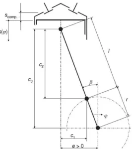
Movement of the piston in conventional IC engines is based on relatively simple kinematics [19]. Figure 1 shows the kinemat-ics of a crankshaft drive with crossing, in which the longitudinal crankshaft axis does not intersect with the longitudinal cylinder axis, but rather is displaced by the offset e.
For the piston path s(j), eq. (1) follows from fig. 1:
2 2
2 2
( ) ( )
sin( ) cos( )
s r l e
l e r r (1)
Through this kinematics, movement of the piston is very limited. In thermodynamic Otto cycle conventional piston movement yields changes of working fluid shown in fig. 2.
Figure 2. PV and TS diagram of conventional Otto cycle
As in fig. 2, the compression 1-2 process is isentropic; the heat addition 2-3, an isochoric process; the expansion 3-4, an isentropic process; and the heat rejection 4-1, an isochoric process. For the heat addition (2-3) and heat rejection (4-1) stages, respectively, it is assumed that heating occurs from state 2 to state 3 and cooling ensues from state 4 to state 1.
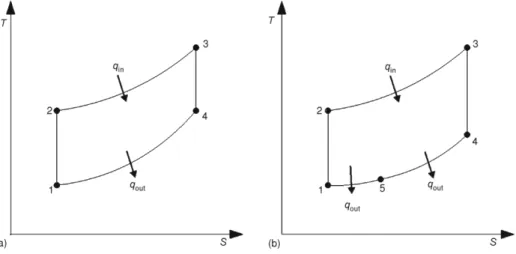
One of many reasons for such small efficiency of spark ignition engines is associated with point 4 from fig. 2, in other words at the end of expansion the pressure and temperature of working fluid are still very high. It is very important in terms of better fuel efficiency that the average temperature of heat rejecting be as low as possible. Now it can be analyzed how reducing the temperature of heat rejecting affects on changes in temperature--entropy (TS) diagram. Figure 3(a) shows the TS diagram of thermodynamic Otto cycle, and
in fig. 3(b) is presented how with lower temperature at the end of expansion stroke thermodynamic cycle gets larger area of TS diagram. The main feature of TS diagrams is the equivalence between the area in the diagram and efficiency. When working fluid changes temperature and entropy during a process and prescribes a closed curve within the TS diagram the area enclosed by this curve is proportional to the efficiency.
Figure 3. Reducing the temperature at the end of expansion stroke in order to increase the surface of TS diagram; (a) Otto cycle, (b) Miller cycle
But for such a low temperature at the end of expansion, engine must have a large expansion volume, i. e. engine must have a long expansion stroke. Actually has to have a greater expansion stroke than compression stroke. Conventional IC engine is not able to provide a longer expansion stroke than compression stroke. The main reason for this is relatively simple kinematics, which provides all the strokes of equal length, as can be seen from kinematics scheme of conventional IC engines shown in fig. 1.
It is obvious that is very important for thermodynamic efficiency that temperature at the end of expansion be as small as possible. As stated above this lower temperature will give a larger surface of TS diagram. With conventional piston mechanism is very difficult to achieve this motion. In new IC engines this complex movement can be perform much easier. It is essential for modern IC engines to use energy obtained through more complete expansion cycle, because this way of using fuel energy has significant advantages, for example:
less fuel consumption,
less heating of the environment, and less pollution.
Basic description of the new IC engine
As seen in fig. 4, in this case to the conventional piston mechanism scheme is added one more move-ment (rotation) of cylinders around axis at exactly defined position. Precisely defined position of the crankshaft and movable cylinders is very important, because these values (E1 and E2) define more
com-plete expansion of working fluid and full discharge combustion chamber of the residual products of com-bustion, impact of these values on more complete expansion and compression ratio are described in [20, 21]. Gear ratio between crankshaft and movable cylinders is –1, in this way piston for one revolution make all four strokes. Described mechanism allows the realization of strokes with different lengths.
Such kinematics would allow different pressure variation as a function of volume. One such example of pressure-volume (PV) diagram is shown in fig. 5
and 6, where it can be seen how with this motion piston can reach much lower value of pressure at the end of expansion. It is also noted that the longest stroke is actually exhaust stroke and the shortest one is compression stroke.
Figure 5. PV diagram of the conventional IC engine
Figure 6. PV diagram of the new IC engine
The described kinematics scheme can be implemented in several ways, in this case was chosen a way which was described in detail in [20]. This paper will only briefly present the basic design of radial-rotary valveless IC engine with more complete expansion, cross--section of this engine can be seen in fig. 7.
Basic parts of the engine are shown in fig. 7. The engine consist of the lower part of engine housing (1) and the upper part of the engine housing (2), movable cylinders-rotors (9), in which are placed pistons (6), connected to the crankshaft (5), through the piston rod (7) and piston pin (8), with (3) and (4) are presented intake and inlet manifold, respectively, and with (10) and (11) are described gear mechanisms. Pistons are placed radial to the crankshaft, whereby the rotation axis of crankshaft located at precisely defined position.
It is interesting to make an analysis of piston movement. In this case movement of the piston is not a linear, because in this engine mechanism forces the piston to move over curve. Piston is moving on very complex trajectory and this curve is very similar to ellipse. The parameters of this curve depend on the values of the following factors: crankshaft radius, connecting rod length, and also of values of eccentric parameters E1 and E2. It is clear that with
these parameters it is easy to achieved very large number of different types of curves, in other words different type of piston motion laws. In this type of kinematics chain small changes of values are reflected in wide variations. For example, angular velocity must be of the same intensity for the movable cylinders and crankshaft, but opposite directions. Also the gear ratio must be respected, only in this case engine can reach the proper cycle operation [21]. Hereinafter will be analyzed how this construction of IC engine has the effect on piston strokes.
Such a diagram is shown in fig. 8, where is represented the dependence of the piston distance from rotation axis of movable cylinders. From the diagram it can be observed that all four strokes have different lengths. Different values of strokes actually cause the changes of cylinder volume, which was previously mentioned as necessary in terms of greater efficiency. The values of the length of strokes can be easily changed depending on desired ratio of compression and expansion ratio. In this case, the tendency was to accomplish the compression ratio of approximately 10.3.
Figure 8. Piston distance depending on angle of crankshaft [16]
By changing described values, the engine can achieve much higher expansion ratio than standard conventional IC engine. This is very important because, with longer expansion stroke working fluid can reach much lower temperature at the end of expansion. According to fig. 3 it is clear that with the reduction of T4 (temperature at the end of expansion) cycle
achieves the lower temperature during the rejecting the heat and also lower pressure at the end of expansion.
Unconventional engine cycle
The Miller cycle, named after its inventor R. H. Miller, has an expansion ratio exceeding its compression ratio. The Miller cycle, is a modern modification of the Atkinson cycle (i. e. a complete expansion cycle). In the Miller cycle, the intake valve is left open longer than it would be in an Otto cycle engine. In effect, the compression stroke is two discrete cycles: the initial portion when the intake valve is open and final portion when the intake valve is closed. In new valveless IC engine with more complete expansion of working fluid Miller cycle is achieved in a different way, through kinematics described in fig. 4 and explained in detail in [21].
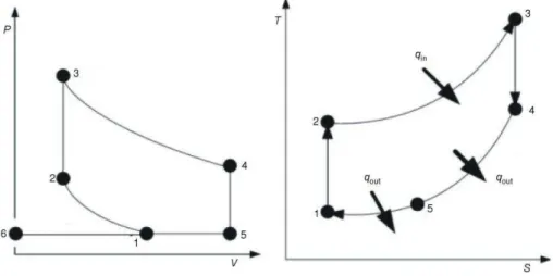
The main difference between Miller`s cycle and the new cycle is closely related to point 6 from the PV diagram in fig. 9. As can be seen from the PV diagram, volume at the end of exhaust is equal to zero. Certainly, volume with this value is impossible to achieve in real engine, but very close to zero is possible with this IC engine.
With this engine design can be easily achieved such motion where piston at the end of exhaust stroke comes very close to engine housing and remove all products of combustion. One such situation is shown in fig. 7, which shows the moment when piston begins intake stroke. This feature of the mechanism is very important, because in this way all residual products of combustion are removed, and in new fresh mixture there is no products of combustion. In this way heating of a fresh mixture was reduced, and with lower temperature at the end of intake stroke can be achieved greater volumetric efficiency. Also with lower temperature at the beginning of compression stroke higher efficiency can be expected. Since this is the only difference between this unconventional cycle and Miller cycle, in this paper will be analyzed the impact of temperature at the beginning of compression on thermal efficiency.
As in fig. 9, the compression 1-2 process is isentropic; the heat addition 2-3, an isochoric process; the expansion 3-4, an isentropic process; the heat rejection 4-5, an isochoric process and 5-1 an isobaric process. For the heat addition (2-3) and heat rejection (4-5-1) stages, respectively, it is assumed that heating occurs from state 2 to state 3 and cooling ensues from state 4 to state 1.
In practical cycles, specific heats of the working fluid are variable and these variations will have great influences on the performance of the cycle. According to [22], it can be supposed that the specific-heats of the working fluid are dependent on the temperature alone and, over the temperature ranges generally encountered for gases in heat engines (300--2200 K), the specific-heat curve is nearly a straight line, which may be closely approximated by:
p 1
v 1
C a k T
C b k T (2)
where a, b, and k1 are constants and Cp and Cv are the molar specific heats with respect to
constant pressure and volume, respectively. Accordingly, the constant, R, of the working fluid is:
p v
R C C a b (3)
The heat added to the working fluid, during the process 2 ® 3, is:
3 3
2 2
2 2
vd ( 1 ) d [ ( 3 2) 0.5 (1 3 2)]
T T
in
T T
Q M C T M b k T T M b T T k T T (4)
where M is the molar number of the working fluid.
The heat rejected by the working fluid, during the process 4 ® 5, is:
4 4
5 5
2 2
1 vd ( 1 ) d [ ( 4 5) 0.5 (1 4 5)]
T T
out
T T
Q M C T M b k T T M b T T k T T (5)
The heat rejected by the working fluid, during the process 5 ® 1, is:
1 1
5 5
2 2
2 pd ( 1 ) d [ ( 5 1) 0.5 (1 5 1 )]
T T
out
T T
Q M C T M a k T T M a T T k T T (6)
Since Cp and Cv are dependent on temperature, the adiabatic exponent k = Cp/Cv will
vary with temperature as well. Therefore, the equation often used in reversible adiabatic- processes with constant k cannot be used in reversible adiabatic-processes with variable k. However, according to [23, 24] a suitable engineering approximation for a reversible adiabatic-process with variable k can be made, i. e., this process can be broken up into infinitesimally-small processes, and for each of these processes, the adiabatic exponent k can be regarded as a constant. For example, any reversible adiabatic-process between states i and j can be regarded as consisting of numerous infinitesimally-small processes with constant k. For any of these processes, when small changes in temperature dT and in volume dV of the working fluid take place, the equation for a reversible adiabatic process with variable k can be written as:
1 ( d )( d ) 1
TV T T V V (7)
From eq. (7), one gets:
1( ) ln ln
j j
j i
i i
T V
k T T b R
T V (8)
5 1
e
2 2
V V
r
V V (9)
As regards of the particular engine, compression ratio will have constant value. Criteria that were considered during the selection of this value can be seen in [20].
Therefore, equations describing processes 1-2 and 3-4 are, respectively, as:
2 1
1 2 1
1 2
( ) ln T ln V
k T T b R
T V (10)
3 3
1 3 4
4 4
( ) ln T ln V
k T T b R
T V (11)
For an ideal cycle model, there are no heat-transfer losses. However, for a real cycle, heat-transfer irreversibility between the working fluid and the cylinder wall is not negligible. It is assumed that the heat loss through the cylinder wall is proportional to the average temperature of the working fluid and the cylinder wall, and that, during the operation, the wall temperature remains approximately invariant. The heat added to the working fluid by combustion is given by the linear-relation [6]:
in 2 3
Q M A B T T (12)
where A and B are constants related to the combustion and heat-transfer processes.
When the values of e, re, T1 are given, T2 can be obtained from eq. (10), then
substituting from eq. (4) into eq. (12) yields T3, and T4 can be found using eq. (11). The last
unknown is T5, which can be deduced from the entropy change assuming an ideal-gas: the
entropy change DS3®2 between states 2 and 3 is equal to the entropy change DS4®1 between
states 4 and 1. Explained in eqs. (13) and (14):
3 2 4 1 4 5 5 1
S S S S (13)
v p
d d d dP
dS C T R V or dS C T R
T V T P (14)
Processes 2-3 and 4-5 occur at constant volume and 5-1 is a constant pressure process. By substituting the specific heat from eq. (2) and integrating from the initial to the final state of the process, then:
3 4 5
1 3 2 4 1
2 5 1
lnT lnT lnT ( ) 0
b a k T T T T
T T T (15)
Substituting T1, T2, T3, and T4 into eq. (15), we get T5 and substituting T1, T2, T3, T4,
and T5 into eq. (18) permits the efficiency to be estimated. Then can be derived relations
th in
W
Q (16)
and work per cycle is equal to the difference between added and rejected heat:
in out
W Q Q (17)
Expression for thermal efficiency becomes:
4 1
5 5
3
2
v p
th
v
d d
1
d
T T
T T
T
T
M C T M C T
M C T
(18)
Results and discussion
The following constants and parameter values have been used in this paper: A = = 60,000 J/mol, B = 25 J/mol, T1 = 293, 308, and 340 K, k1 = 0.004, 0.006, and 0.008
J/molK2, b = 20, 21, and 22 J/molK, a = 28 J/molK, re =1-27, and e = 10.3. Cases were
studied numerically for values of the k1 = 0.004, 0.006 or 0.008 , b = 20, 21 or 22, T1 =
293, 308 or 340 and for re = 1-27.
From fig. 10 can be seen the impact of parameter k1 on the values of temperatures
during compression and expansion for the constant value of parameter b, while fig. 11 shows the opposite situation in this case constant value of the parameter k1 was used. Analysis of
figs. 10 and 11 shows that the parameter b has a greater influence on the final temperature during the compression and expansion.
Figure 10. Influence of parameter k1 on the values of temperatures during compression and
expansion (b = 20 J/molK, T1 = 308 K, re = 15)
Figure 11. Influence of parameter b on the values of temperatures during compression and expansion (k1 = 0.008 J/molK2, T1 = 308 K,
re = 15)
The thermal efficiency decreases with increases of k1 and b. The effect of changing
k1 is less than for b. This is due to the increase of the heat rejected by the working fluid and
efficiency decreases sharply even with only a slight increase of b. This is due to the increase in the heat rejected by the working fluid as a result of increasing b– see eq. (5). According to the above analysis, it can be concluded that the effects of the temperature dependent specific heat of the working fluid on the cycle performance are significant, and should be considered carefully in practical-cycle analysis and design. The parameter k1 reflects the variation degree
of the specific heat with temperature. The bigger k1 is, the more acutely the specific heat
varies with temperature.
The main features of the described concept is more complete expansion, in accordance with that was analyzed how expansion ratio has an impact on thermal efficiency; the results are shown in fig. 12. It can be concluded that thermal efficiency increases with increasing expansion ratio in the beginning, but after reaching the maximum value with further increase of expansion ratio a reduction in efficiency is inevitable.
Figure 12. Effect of k1 on the variation of the efficiency with expansion ratio (T1 = 308 K,
b = 20 J/molK)
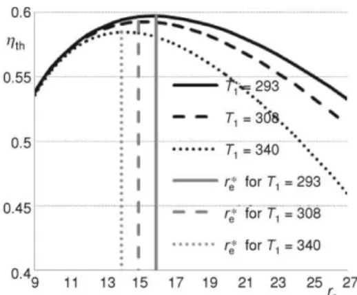
Figure 13. Effect of T1 in the variation of the efficiency with expansion ratio
(k1 = 0.004 J/molK2, b = 20 J/molK2)
The analysis in terms of reduced temperature at the beginning of compression stroke was performed also. Figure 13 shows the effect of T1 on thermal efficiency as a function of
expansion ratio. It is proven that with decreasing temperature at the beginning of compression has a positive impact on thermal efficiency, although it is evident that with decreasing T1, point of
maxi-mum thermal efficiency is obtained for larger values of expansion ratio, these values of expansion ratios at maximum thermal efficiency are marked with re*.
From the numerical results, it can be concluded that it is of great importance to realize complete expansion of working fluid in engine cylinder. In fig. 14 are described how values of k1 and b have
impact on efficiency in conventional
Figure 14. The impact of k1 and b on improving
efficiency in relation to the standard Otto cycle (T1 = 308 K, re = 15, k1 = 0.008 J/molK2
when b is a
variable, b = 20 J/molK1
Otto cycle and in proposed new cycle. It is obvious that in any case there is an improvement of efficiency. The thermal efficiency decreases with increases values of k1 and b, but with the
increase of these values improving efficiency in relation to the standard Otto cycle also increases, it can be seen from fig. 14.
Comparing the final temperature of both cycles it can be concluded that in new more complete expansion cycle, temperature at the end of expansion are much lower. According to fig. 3 it is clear that with the reduction of T4 cycle achieves a higher thermal efficiency.
Finally in fig. 14 are shown how this new thermodynamic cycle for IC engine have impact on the thermal efficiency in relation to the standard Otto cycle.
From the results show in fig. 13. it may be noted that the highest thermal efficiency in relation to T1 is achieved when the expansion ratio is whitin the limits from 14 to 16. As
was mentioned, with varying the values of parameters E1 and E2 desired compression
ration and expansion ratio can be easily achieved. In accordance with the results from fig. 13 in this paper was also presented the CAD model of the internal combustion engine that has expansion ratio of 15 (fig. 15). This is the optimal value of expansion ratio according to the results for the T1 = 308 K. That basically
means that in this case expansion stroke is more than 50% longer than compression stroke. The same figure shows the situation when both pistons are in BDC. Piston on the left side is in the position at the end of the intake stroke, while for the right piston expansion stroke has just been completed.
Conclusions
Automobile industry is under a large pressure to keep developing automobiles with IC engines, to reduce fuel consumption and exhaust gas emmisions, as well as to seek better alternatives for vehicle drive. In this article was presented one of the possible alternative for conventional internal combustion engine cycle.
Using finite-time thermodynamics, the relations between thermal efficiency and thermodynamic constants for an ideal naturally-aspirated (air-standard) new cycle have been derived. The finite-time thermodynamic model of realistic reciprocating heat-engines is a powerful tool for understanding and optimizing the performance of a reciprocating heat--engine. In this paper was examined the thermodynamic model of a new IC engine. The engine was designed so that the changes in the thermodynamic state of the working fluid are very similar to Miller cycle. The efficiency curves are calculated and represented for few numerical examples. As can be seen from the graphic in fig. 14, a more complete expansion of the working fluid contributes to increasing efficiency. Also with this concept lower temperatures at the end of expansion can be reached as shown in figs. 10 and 11; this feature is very important for the environment. A slight increase in some parameters will have a significant impact on the thermal efficiency of the studied cycle. The results obtained from this research are compatible with those in the open literature, for other cycles, and may be
used with assurance to provide guidance for the analysis of the behavior and design of some other practical Miller or Atkinson engines.
Future studies should discuss the possible effects of mechanical losses of this concept, in order to achieve values not only thermal efficiency but also mechanical efficiency of IC engines with more complete expansion accurately represented in [20, 21].
Nomenclature
A – constant [Jmol–1] a – constant, [Jmol–1K–1] B – constant, [Jmol–1] b – constant, [Jmol–1K–1]
Cp – specific heat under constant pressure, – [Jmol–1K–1]
Cv – specific heat under constant volume, – [Jmol–1K–1]
e – eccentricity, [m]
E1 – eccentricity in x-axis, [m] E2 – eccentricity in y-axis, [m] k1 – constant, [Jmol–
1 K–2] l – connecting rod length, [m] M – molar mass, [kgmol–1] P – pressure, [Pa] Qin – added heat, [J]
Qout1 – rejected heat during constant volume, [J] Qout2 – rejected heat during constant pressure, [J] R – gas constant, [Jkg–1K–1]
r – crankshaft radius, [m] re – expansion ratio, [–]
re* – expansion ratio at maximum thermal – efficiency, [–]
S – entropy, [Jkg–1K–1]
s – piston path, [m]
T – temperature, [K]
V – volume, [m3]
W – work [J]
Greek symbols
b – angle, [°]
e – compression ratio, [–]
hth – thermal efficiency, [–]
k – adiabatic exponent (= Cp/Cv), [–]
j – crankshaft angle, [°] Subscripts
1 – gas state at the beginning of compression 2 – gas state at the end of compression 3 – gas state at the beginning of expansion 4 – gas state at the end of expansion 5 – gas state after rejecting the heat during
– constant volume Acronyms
BDC – bottom dead center CAD – computer aided design
References
[1] Gruden, D., On the Future of Power Plant for Motor Vehicles, Proceedings, International Congress Motor Vehicles & Motors 2010, Kragujevac, Serbia, 2010, pp. 25-43
[2] Klinar, I., Internal Combination Engines, Faculty od Technical Sciences, University of Novi Sad, Novi Sad, Serbia, 2008
[3] Gligorijević, R., et al., Potentials and Limitations of Alternative Fuels for Diesel Engine, Thermal Science 13 (2009), 3, pp. 175-183
[4] Andresen, B., Salamon, P., Berry, R. S., Thermodynamics in Finite Time, Physics Today, 9 (1984), 9, pp. 62-70
[5] Al-Sarkhi, A., Jaber, J. O., Probert, S. D., Efficiency of a Miller Engine, Appllied Energy, 83 (2006), 4, pp. 343-351
[6] Orlov, V. N., Berry, R. S., Power and Efficiency Limits for Internal-Combustion Engines via Methods of Finite-Time Thermodynamics, Jornal of Applied Physics, 74 (1993), 10, pp. 4317-4322
[7] Ge, Y., et al., Thermodynamic Simulation of Performance of an Otto Cycle with Heat Transfer and Variable Specific Heats of Working Fluid, International Journal Thermal Sciences, 44 (2005), 5, pp. 506-511
[8] Ge, Y., et al., Performance of Diesel Cycle with Heat Transfer, Friction and Variable Specific Heats of Working Fluid, Journal of the Energy Institute, 80 (2007), 4, pp. 239-242
[10] Ge, Y., et al., Performance of Reciprocating Brayton Cycle with Heat Transfer, Friction and Variable Specific Heats of Working Fluid, International Journal of Ambient Energy, 29 (2008), 2, pp. 65-75 [11] Chen, L., et al., Effects of Heat Transfer, Friction and Variable Specific Heats of Working Fluid on
Performance of an Irreversible Dual Cycle, Energy Conversion Management, 47 (2006), 18-19, pp. 3224-3234
[12] Ge, Y., et al., Performance of an Endoreversible Diesel Cycle with Variable Specific Heats of Working Fluid, International Journal of Ambient Energy, 29 (2008), 3, pp. 127-136
[13] Ge, Y., Chen, L., Sun, F., Finite Time Thermodynamic Modeling and Analysis for an Irreversible Atkinson Cycle, Thermal Science, 14 (2010), 4, pp. 887-896
[14] Ge, Y., et al., Performance of a Reciprocating Endoreversible Brayton Cycle with Variable Specific Heats of Working Fluid, Termotehnica, 12 (2008), 1, pp. 19-23
[15] Ge, Y., et al., Effects of Heat Transfer and Variable Specific Heats of Working Fluid on Performance of a Miller Cycle, International Journal of Ambient Energy, 26 (2005), 4, pp. 203-214
[16] Chen, L., et al., The Performance of a Miller Cycle with Heat Transfer, Friction and Variable Specific Heats of Working Fluid, Termotehnica, 14 (2010), 2, pp. 24-32
[17] Pulkrabek, W.W., Engineering Fundamentals of the Internal Combustion Engine, Prentice Hall, Upper Saddle River, N. J., USA, 1997
[18] Chen, L., Lin, J., Sun, C., Efficiency of an Atkinson Engine at Maximum Power Density, Energy Conversion Management, 39 (1998), 3-4, pp. 337-341
[19] Merker, G., et al., Simulating Combustion, Springer-Verlag, Berlin Heidelberg, Germany, 2006 [20] Dorić, J., Radial-Rotary Valveless Four-Cycle IC Engine with More Complete Expansion, the Patent
Application Material under Number 2008/607 at the Intellectual Property Office of the Republic of Serbia, 2008
[21] Dorić, J., The Conception of the Valveless Four Cycle IC Engine with More Complete Expansion of the Working Fluid, M. Sc. thesis, University of Novi Sad, Novi Sad, Serbia, 2008
[22] Ghatak, A., Chakraborty, S., Effect of External Irreversibilities and Variable Thermal Properties of Working Fluid on Thermal Performance of a Dual Internal Combustion Engine Cycle, J. Mechanical Energy, 58 (2007), 1, pp. 1-12
[23] Ge, Y., et al., Thermodynamic Simulation of Performance of an Otto Cycle with Heat Transfer and Variable Specific Heats of Working Fluid, International Journal Thermal Sciences, 44 (2005), 5, pp. 506-11
[24] Ge, Y., et al., Effects of Variable Specific Heats on the Performance of an Irreversible Otto Cycle, International Journal of Exergy, 2 (2005), 3, pp. 274-283
![Figure 6. PV diagram of the new IC engine The described kinematics scheme can be implemented in several ways, in this case was chosen a way which was described in detail in [20]](https://thumb-eu.123doks.com/thumbv2/123dok_br/17314589.249389/5.893.317.704.595.816/figure-diagram-engine-described-kinematics-scheme-implemented-described.webp)