“Mircea cel Batran” Naval Academy Scientific Bulletin, Volume XIX – 2016 – Issue 2
The journal is indexed in: PROQUEST / DOAJ / Crossref / EBSCOhost / INDEX COPERNICUS / DRJI / OAJI / JOURNAL INDEX / I2OR / SCIENCE LIBRARY INDEX / Google Scholar / Academic Keys/ ROAD Open Access /
Academic Resources / Scientific Indexing Services / SCIPIO / JIFACTOR
A METHOD TO ACQUIRE AND PROCESS THE ANALOG RADAR SIGNAL
Ovidiu CRISTEA1 Nicolae BADARA2
Aurelian-Sorinel CALINCIUC3 Andrei ANDRIES4
1
Teaching assistant, PhD Student, “Mircea cel Batran” Naval Academy,Constanta, Romania
2
Lecturer PhD, “Mircea cel Batran” Naval Academy,Constanta, Romania
3
Engineer, ANCOM Bucharest, Romania
4
Student , “Mircea cel Batran” Naval Academy,Constanta, Romania
Abstract: In our days the RADAR systems are essential to navigation for maritime, aeronautical and
terrestrial applications. Basic RADAR systems were developed using analog components and some of this RADARs are still functioning due there good performances and redundancy; a very good example is found onboard of military vessels. Because in our days the RADAR systems are digital and because these RADARs need to work in the same network with the analog RADARs, this fact conducts to a much debated research theme: to realize a RADAR extractor which will make the analog RADARs compatible with digital ones.
Key words: LabView, Radar extractor, data acquisition and processing
INTRODUCTION
RADAR (Radio Detecting And Ranging) is an electromagnetic system used to detect and locate reflecting objects. A pulse radar is a radar system that emits short pulses in order to receive the echo signals in the rest time. The main elements of a pulse radar system are shown in the figure 1.
Figure1.Pulse radar’s block diagram
The pulse radar operation can be described in a very simplified way as follows:
The transmitter or the power amplifier generates a proper waveform for the scope the radar is to perform.The power might range from miliwatts to megawatts. The main objective of duplexer or switch is to commute the antenna from transmitting to receiving mode in order to protect the input circuit to be damaged during high power electromagnetic transmission. Electromagnetic energy radiated from an antenna into space is redirected back to radar system by reflecting objects. In receiving mode this energy is collected
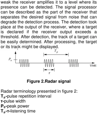
and sent to receiver. Because the echo signal is weak the receiver amplifies it to a level where its presence can be detected. The signal processor can be described as the part of the receiver that separates the desired signal from noise that can degrade the detection process. The detection took place at the output of the receiver, where a target is declared if the receiver output exceeds a threshold. After detection, the track of a target can be easily determined. After processing, the target or its track might be displayed.
Figure 2.Radar signal
Radar terminology presented in figure 2:
Tp-pulse repetition interval τ-pulse width
P0-peak power
Tp-τ-listening time
The difference between signals from the figure 3 and 4, and the figure 2 can be summarized in terms of processing. The picture above show the signal in its raw format while in the next two pictures the signal is in its video format.
187 DOI: 10.21279/1454-864X-16-I2-027
“Mircea cel Batran” Naval Academy Scientific Bulletin, Volume XIX – 2016 – Issue 2
The journal is indexed in: PROQUEST / DOAJ / Crossref / EBSCOhost / INDEX COPERNICUS / DRJI / OAJI / JOURNAL INDEX / I2OR / SCIENCE LIBRARY INDEX / Google Scholar / Academic Keys/ ROAD Open Access /
Academic Resources / Scientific Indexing Services / SCIPIO / JIFACTOR
Figure 3.Theoretical video RADAR signal
The video signal represents the output of the pulse detector. So, the signal reflected by targets
is sent to receiver to be amplified. Then it is mixed with a signal generated by a local oscillator and
the result – intermediary frequency signal – is applied to pulse detector. Other relevant explications can be found in [1]–[4] and [5]–[11].
Figure 4. RADAR Extractor video signal simulated in LabView[12]
RADAR EXTRACTOR
The main role of an extractor is to detect,extract and estimate target’s parameters from an analog signal and convert them in a digital format using a protocol.Video signal is received from different sensors and it is processed in order to get the most accurate data. Figure 5 shows how received analog signal is sampled in time and how the values of signal amplitude are distributed in a matrix or a range gate.
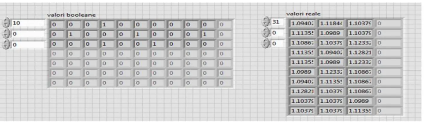
Our RADAR Extractor is based on a true/false matrix for storing the targets and their parameters. For each cycle of the RADAR the program generates a matrix with targets’ parameters, which can be used to obtain a matrix with real parameters of the targets. A print screen, from RADAR Extractor program front panel, with this process is presented in figure 6. In the left side of the figure are presented the Boolean values of the targets, meanwhile in the right side are presented
the real values ones. Figure 5. Extraction of target’s parameters
188 DOI: 10.21279/1454-864X-16-I2-027
“Mircea cel Batran” Naval Academy Scientific Bulletin, Volume XIX – 2016 – Issue 2
The journal is indexed in: PROQUEST / DOAJ / Crossref / EBSCOhost / INDEX COPERNICUS / DRJI / OAJI / JOURNAL INDEX / I2OR / SCIENCE LIBRARY INDEX / Google Scholar / Academic Keys/ ROAD Open Access /
Academic Resources / Scientific Indexing Services / SCIPIO / JIFACTOR
Figure 6. RADAR Extractor Boolean and Real values for acquired data
In the figure 6 every value of 1 (true) represents a target(amplitude of sample that exceeds the value of a predetermined threshold) and every 0 (false) value represents an empty space on the RADAR’s display. Now, to make the RADAR Extractor useful for other RADARs, the targets’ parameters need to be converted in a plotted format (polar coordinates) and also every target from matrix must be plotted on graph that can be implemented and displayed by an ordinary PC.
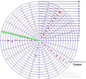
Our LabView program transform a high sample rate data acquisition board in a RADAR Extractor and can transmit the targets’ parameters to other user who can display the targets in RADAR format, as you can see in figure 8. In the figure 7 is presented the RADAR Extractor block diagram, which is a program written in LabView, using virtual instruments. The exact operation of the program is not presented in order to protect our research work.
Figure 7. RADAR Extractor LabView block diagram
The figure 8 presents the RADAR extractor display, which can be installed on a windows running computer. With the red dots are represented the targets extracted from the simulated signal. The green line represents the azimuth of the RADAR antenna, also it can be called the refresh information line.
189 DOI: 10.21279/1454-864X-16-I2-027
“Mircea cel Batran” Naval Academy Scientific Bulletin, Volume XIX – 2016 – Issue 2
The journal is indexed in: PROQUEST / DOAJ / Crossref / EBSCOhost / INDEX COPERNICUS / DRJI / OAJI / JOURNAL INDEX / I2OR / SCIENCE LIBRARY INDEX / Google Scholar / Academic Keys/ ROAD Open Access /
Academic Resources / Scientific Indexing Services / SCIPIO / JIFACTOR
Figure 8. RADAR Extractor display chart
CONCLUSIONS
The RADAR Extractor presented in the article is a product of a 3 years of research. We have continued our first project[12] and we have succeeded to improve our program. In the moment we decided to share our project through this article, the RADAR Extractor was able to:
• Precisely convert RADAR video signal in digital format using high rate data acquisition FPGA board;
• Extract targets and their parameters from digital signal using a flexible and real time adaptable algorithm;
• Save the target’s parameters in a powerful low memory format;
• To share acquired information using the most known protocols used by PCs
• Display targets in RADAR format (polar coordinates).
For future, the research team will try to develop the processing module of the project and the communications one. Also, a prototype is planned for testing our RADAR Extractor in real conditions.
BIBLIOGRAPHY
[1] R. M. O’Donnell and C. E. Muehe, “Automated Tracking for Aircraft Surveillance Radar Systems,”
IEEE Trans. Aerosp. Electron. Syst., vol. AES-15, no. 4, pp. 508–517, Jul. 1979.
[2] G. F. Floyd, “Radar Tracking Systems,” Trans. IRE Prof. Gr. Aeronaut. Navig. Electron., vol.
PGAE-8, p. 5–a–5–a, Jun. 1953.
[3] M. Klein and N. Millet, “Multireceiver passive radar tracking,” IEEE Aerosp. Electron. Syst. Mag., vol. 27, no. 10, pp. 26–36, Oct. 2012.
[4] D. Tiranti, R. Cremonini, F. Marco, A. R. Gaeta, and S. Barbero, “The DEFENSE (debris Flows triggEred by storms – nowcasting system): An early warning system for torrential processes by radar storm tracking using a Geographic Information System (GIS),” Comput. Geosci., vol. 70, pp. 96–109, Sep. 2014.
[5] V. Hansen and B. Olsen, “Nonparametric Radar Extraction Using a Generalized Sign Test,” IEEE
Trans. Aerosp. Electron. Syst., vol. AES-7, no. 5, pp. 942–950, Sep. 1971.
[6] V. Iglesias, J. Grajal, O. Yeste-Ojeda, M. Garrido, M. A. Sanchez, and M. Lopez-Vallejo, “Real-time radar pulse parameter extractor,” in 2014 IEEE Radar Conference, 2014, pp. 0371–0375.
[7] K. Kilinc and F. Gebali, “Ship detection and property extraction in radar images using hardware,” in 2015 IEEE Pacific Rim Conference on Communications, Computers and Signal Processing (PACRIM), 2015, pp. 518–523.
[8] Z. Lu, F. Li, and T. Zeng, “Monopulse radar angle extractor of multiple unresolved targets via matching pursuits,” in IET International Radar Conference 2013, 2013, pp. 0742–0742.
[9] N. Mohajerin, J. Histon, R. Dizaji, and S. L. Waslander, “Feature extraction and radar track classification for detecting UAVs in civillian airspace,” in 2014 IEEE Radar Conference, 2014, pp. 0674–0679.
[10] D. Tahmoush and J. Silvious, “Radar Stride Rate Extraction,” in 2009 13th International Machine Vision and Image Processing Conference, 2009, pp. 128–133.
[11] G. Zhang, W. Jin, and L. Hu, “Fractal feature extraction of radar emitter signals,” in Asia-Pacific Conference on Environmental Electromagnetics, 2003. CEEM 2003. Proceedings., 2003, pp. 161–164.
[12]N. Badara and O. Cristea, “RADAR Extractor,” Int. Conf. NAV-MAR-EDU 2013, no. May 30th –June 01st,
Constanta, 2013.
190 DOI: 10.21279/1454-864X-16-I2-027