Balwinder singh
1, Sukhleen Bindra Narang
2, and Arun Khosla
31Centre for Development of Advanced Computing (CDAC), Mohali, India
(A scientific Society of Ministry of Comm. & Information Technology, Govt. of India)
2Electronics Technology Department, Guru Nanak Dev University, Amritsar, India
3 ECE Department Dr. B .R. Ambedkar National Institute of Technology, Jalandhar, India
Abstract
In today’s Integrated Circuits (IC’s) designs Built-in Self Test (BIST) is becoming important for the memory which is the most necessary part of the System on Chip. The March algorithm has been widely used to test memory core of System on chip (SOC). LFSRs and counters are mainly used to generate the memory addresses, which can be serially applied to the memory cores under test. In this paper Address counters and Data generators (i.e. parts of the MBIST) are designed. These implemented in Hardware Description Language (HDL), and the area and power analyzed for each case . From the analyzed results the low power LFSRs and counters can be identify for the low power memory BIST design.
Keywords:BIST, Low power, Address counter, Test Pattern Generators.
.
1.
Introduction
emiconductor memories are considered one of the most important aspects of modern VLSI Systems. Memories are the most important universal components in System on chip today. Almost all SOC’s contain some type of embedded memories, such as ROM, RAM, DRAM and flash memory.
According to the International Technology Roadmap for Semiconductors (ITRS 2007) [1]. Semiconductor memories will occupy the 90% of the total chip area by 2012. Testing the memory IP in SOC becomes more important because the memory density higher than the logic part, which means the chance to have a d efect is higher in memory. The quality of embedded memory can dominant overall quality and profitably of the whole chip. The BIST methodologies offer solutions for testability of embedded memories and minimize the embedded memory tester’s requirements and reduce memory test time.
Power dissipation becomes a serious concern in memory IP’s with Memory BIST features, due to the switching activity in the Memory under Test. The algorithms which are used for the testing of memory parts work on the read and write operations with particular sequence of. For example
{↕(w0); ↓(r0,w1); ↑(r1,w0,r0,w1); ↑(r1,w0); ↑(r0,w1,r1,w0); ↑(r0)}.
The March LR [2] algorithm is a popular testing algorithm in industry [3]. The read and writes operations require a lot of switching in test pattern generators and address counters. It is important to control this switching activity. In this paper the power dissipation in TPG generator and address counters is analyzed.
The related work done by various researchers is discussed in section 2 and section 3 gives the brief overview the power dissipation sources in CMOS devices and importance of low power testing. In section 4, discussion on Memory BIST methodology and address counter / generators is given. Section 5 results of each are compared bases on the power and area and finally concluded in section 6.
2.
Related Work
Shilesh Malliyoor et.al [4] gives comparison of hardware implementation and power consumption of low-power multiple output linear feedback shift register (LFSR). In this paper two architectures (i.e. Kitty and Lowy) are implemented and compared for a s pecific application of E0 stream cipher.
Douglus M.Gant [5] discussed automated techniques used to recognize and develop symmetries in address sequences using modulus m counter which is better than, those designed by hand. Tomoaki Sato et. al [6] analyzed the performance of a wave-pipelined LFSR. The simulation
Address Counter / Generators for Low Power Memory BIST
results of the proposed work has shown the improvement than the previous design in terms of speedup and power saving.
Erastus Ogunti et.al. [7] proposed Design of a Low Power Binary counter using bistable storage element is used. they had also compared their work with standard 8 bi t binary counter design as flip flops of 50 µm process and recorded a power advantages of 60 %. Sreehari Veeramachaneni [8] proposed a high-Speed Binary and Gray Incrementer / Decrementer for an Address Generation Unit .simulation and comparison is done with existing work. Ramesh Kini M.[9] proposed design of Address Generators for DSP applications in complex addressing modes.
S. V. Yarmolik et. al. [10]. proposed the new techniques for memory test address generation for pattern sensitive faults detection. Two types of memory address transformation have been proposed, analyzed and experimentally validated. Doshi N. A. [11] LFSR Counter Implementation based on CMOS techniques with three architectures and compared in terms of power and hardware.
3.
Power Dissipation during VLSI
Testing
Power dissipation is most important factor during the testing of memory part [12]. So it is necessary to discuss here about the static and dynamic power dissipation.
3.1 Dynamic Power Dissipation
Dynamic power dissipation is primarily caused by the current flow from the charging and discharging of parasitic capacitances. It consists of three components: switching power, short-circuit power, and glitching power.
In most CMOS digital circuits, the switching power is the dominant component in power dissipation. The average switching power of the circuit can be calculated from the energy, required to charge up the output node to VDD and discharge the total output load capacitance to ground (GND). The generalized equation for the switching power dissipation of a CMOS logic gate can be calculated from the given equation.
P
avg= αT. C
load. V
2dd. f
clk ……….1 Where,
αT :
Switching activity factor of the gate.C
load : Total load capacitanceV
dd : Supply voltagef
clk :Operating frequencyThe average power is directly proportional to the αT. The power dissipation during testing can be reduced by controlling the switching activity and the load capacitance.
Static Power Dissipation
Static power dissipation is caused by leakage currents when the gates operating in the idle mode (means no output transitions). CMOS gates should not be consuming any power in this mode. But there is always some leakage current passing through the transistors, indicating that the CMOS gates consumes a certain amount of power. Another reason as the level of doping has to be increased due to as transistors shrink in size, thereby causing leakage currents to become larger. It effects only when millions of transistor utilizes this power at same time.
Reasons of power dissipation
The main reasons for the power dissipation during testing are given below:
• According to the Moore’s Law, the transistor density increases after every 18 months. Hence, circuits become more complex and difficult to test. It takes more time to test these circuits, and to save the testing time, partitioning of the circuits is required which leads to high power dissipation.
• Due to lack of at-speed equipments, delay is introduced in the circuit during testing which also dissipate power.
• In the testing mode, the correlation between the consecutive patterns is small which causes large switching and hence increases the dynamic power.
• In normal mode, only a small part of the SOC works but in the test mode all blocks of the SOC remain engaged by applying the large number of test patterns one after the other. Hence, test mode requires more power than normal mode and responsible for increasing chip temperature.
kept low. The low power BIST is used to avoid the risk of damaging the Memory under Test and also. Prevent on-chip power integrity problems in test mode. Low power BIST techniques save the cost of expensive packages or external cooling devices for testing. In SOC testing, IP’s are partitioned into the number of parts and these are tested in parallel to save the time but it c onsumes more power in test mode. [14]
4.
Address Counter /Generators
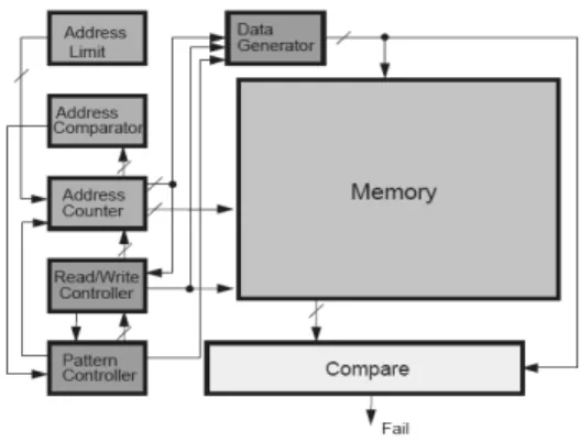
Memory BIST alleviates long test times by incorporating a self-testing logic within the memory itself. MBIST tends to be of much simpler construction, where Address Generator read /write controller, Address counter and, Data generator are the main components of the memory BIST[15][16] as shown in figure 1
Figure 1: Generic architecture of Memory BIST
The main purpose of the address generator is to generate the test patterns. The Linear Feedback Shift Registers (LFSRs) are often used to generate the test pattern. The read/write controller provides the location on the memory where data is to be written during the write operation, data is to be read during the read operation. The read/write controller determines how many cycles a given address is maintained before the address counter is incremented. Data generator interacts with address counter and read/write control logic. It is used to provide the correct data to the memory corresponding to the particular element of the particular test pattern. Address counter interacts with address limiter and address comparator, identifying the proper start and stop address points. The address counter indicates if an even or odd address is being exercised, so that appropriate data can be generated. This counter needs to able to increment or decrement.
4.1
Linear Feedback Shift Register
LFSR is kind of data register in which a clock is used to control the data patterns. The LFSR is characterized by a feedback loop to determine the contents of the LFSR during a state transition. LFSR’s behavior, is in the form of particular the sequence of symbols that is stored after each clock cycle and modeled mathematically.
LFSR module is configured according to characteristic polynomial for generating an output stream of test patterns according to an input stream. E ach LFSR respectively receives a s ub-input stream and at least one feedback stream and respectively generates a sub-output stream and a feedback stream according to the received sub-input stream, wherein the sub-input stream is generated according to the input stream. At least one of the received feedback streams is generated by another LFSR. The output generator generates the output stream according to inputs polynomials. Here below standard form of LFSR is shown in figure 2.
Figure 2: Simple LFSR
4.2
Pipeline LFSR [17]
LFSR allows counting at maximum device speed for practically unlimited bit width of the counter. The cycle length for the LFSR with n bits is 2n – 1. Sometimes, other cycle length may be desired, for that desired purpose, LFSR connections can be easily modified to achieve different cycle length, but at the price higher register-to-register delay and the counter speed goes down. As LFSR speed is the one of the important factor in VLSI testing, so pipelining technique can be used to reduce the register-to- register delay in the LFSR. As shown in the figure 3. In case of LFSR, all output signals are created by the shift register. If this output signal is used as feedback signal, it is equivalent to use of the output value with the index by one lower and with register added into its path.
D FF D
FF FF D FF D
Figure 3 Pipelined LFSR
4.3
Low Power LFSR [21]
Main function of the LFSR in testing is to generate the test patterns for the DUT (Design under test). This is another proposed LFSR in which the correlation between the consecutive test vectors has been increased. This r-injection increases the correlation between the consecutive patterns by disabling the clock of the flip-flop(shown in figure 4)
Figure 4: Low Power LFSR
In this approach the 3 intermediate test vectors are generated between every two successive vectors (say T1, T2). The total number of signal transition occurs between these 5 vectors are equivalent to the number of transition occurs between the 2 vectors. Hence the power consumption is reduced. Additional circuit is used for few logic gates in order to generate 3 intermediate vectors. The 3 intermediate vectors (Ta, Tb, and Tc) are achieved by modifying conventional flip flops outputs and low power outputs. The first level of hierarchy from top to down includes logic circuit design for propagation either the present or next state of flip-flop to second level of hierarchy. Second level of hierarchy is implementing Multiplexed (MUX) function i.e. selecting two states to propagate to output.
4.4
Binary Up down Counter
Binary up down counter is designed in VHDL. It consists of the jk flip-flop. Binary up counter is designed to count the memory location in the memory as shown in figure 5. It counts up by one only wt the positive level edge of the clock or when any event occurs on the cloak. But when the down signal is high and up signal goes low it count by one to downward. Finite state machine is used to design this counter.
Figure 5: Binary Up down Counter
4.5
Gray Code up down counter
Gray counters [18] [10] are based on the gray codes that are the unweighted code that do not have any specific weight assigned to them. The thing which forces the implementation of gray counter (shown in figure 6) is the power utilization. Because in case of the simple binary up down counter when there is step of counting from “0111” then next level is “1000”, which conveys that there is the 4-bit change which consumes more power whereas gray counter is of the only single bit change. The gray counter is beneficial for address up down counting in low power applications due to reduced toggling from one stage to next stage.
5.
Results and Conclusion
The address counter /generators discussed in the previous section were coded in the Hardware Descriptive Language (HDL) and implemented on t he Spartan 3E using Xilinx ISE [24]. The clock frequency after synthesis is 275.334MHz. The verification is done with Mentor Graphics Model Sim 6.4 simulations for each case. The Industry standard high level ISCAS-85 combinational benchmark circuit of C6288 is used to test these designs. The outputs of these LFSR’s and counters are given to the inputs of the c6288 benchmark circuit of ISCAS-85.The code with benchmark circuits are synthesized of each case. The hardware summary is obtained for each method implementation log file as shown in the table 1.
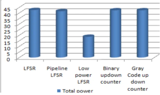
Figure 7: Comparison of Area overhead Address counters and generators
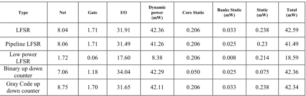
For the analysis of power consumption .vcd file is generated after the post simulation. The power consumption is measure with X-power tool at ambient temperature of 25 degree C, at frequency of 250 MHz, activity rate of 10.0%, DC load of 10mA, cap load of 1000fF and batter capcaity13mA hours, battery life 1.45 hours, the static and dynamic power consumed each case is given in table 2.
Figure 8 : Comparison of Power consumed
Address counters and generators
The comparison of area overhead and power consumed in address counters and generators are shown in figure 7 and figure 8 respectively. It shows that LFSRs used for data and address generation in which low power LFSR is consume less power and less area than normal LFSR .Pipelined LFSR fast speed as it has less register-to- register delay. Gray counter consume less power than binary counter for address counting in both up and down directions as required Memory BIST architectures.
References:
1. International Technology Roadmap for Semiconductors (ITRS),” 2007. [Online]. Available: http://public.itrs.net
2. Van de Goor, A.J., Gayadadjiev, G.N., Yarmolik, V.N., Mikitjuk, V.G.: March LR: A Test for Realistic Linked Faults. In: 16th IEEE VLSI ISE 9.2i Software Test Symposium, pp. 272–280 (1996)
3. van de Goor, A.J. Testing Semiconductor Memories: Theory and Practice. Comtex Publishing: Gouda, Netherlands, 1998
4. Shilesh Malliyoor1 and Chao You2 Comparison of hardware implementation and power consumption of low-power multiple output linear feedback shift register Journal of Engineering, Computing & Architecture Volume 1, Issue 1, 2007
5. Grant, D.M.; Denyer, P.B.; , "Address generation for array access based on modulus m counters," Design Automation. EDAC., Proceedings of the European Conference on , vol., no., pp.118-123, 25-28 Feb 1991 6. Sato, T. Sakuma, R. Miyamori, D. Fukaset, M. 2004. Performance analysis of wave-pipelined LFSR IEEE International Symposium on Communications and Information Technology, ISCIT 2004.Vol.2 pp.694 – 699
7. Ogunti, E.; Frank, M.; Foo, S.;, "Design of a low power binary counter using bistable storage element," Electronic Design, 2008. ICED 2008. International Conference on , vol., no., pp.1-5, 1-3 Dec. 2008 8. Veeramachaneni, S.; Avinash, L.; Kirthi, K.M.;
Srinivas, M.B.; "A novel high-speed binary and gray Incrementer / Decrementer for an address generation unit," Industrial and Information Systems, 2007. ICIIS 2007. International Conference on , vol., no., pp.427-430, 9-11 Aug. 2007
9. Ramesh, K.M.; Sumam, D.S.; , " Comprehensive address generator for digital Signal Processing," Industrial and Information Systems (ICIIS), 2009 International Conference on , vol., no., pp.325-330, 28-31 Dec. 2009
System, 2006. MIXDES 2006. Proceedings of the International Conference , vol., no., pp.572-576, 22-24 June 2006
11. Doshi N. A., Dhobale S. B., and Kakade S. R.LFSR Counter Implementation in CMOS VLSI. Journal of World Academy of Science, Engineering and Technology 48 2008
12. Crouch A.(1999). Design-for-Test for Digital I C's and Embedded Core Systems, Prentice Hall, 1999 13. E. Atoofian, S. Hatami, Z. Navabi, M. Alisafaee and
A. Afzali-Kusha,”A New Low-Power Scan-Path Architecture,” IEEE International Symposium, Vol.5, pp.5278 – 5281, 23-26 May 2005
14. Chun-Yi Lee, James Chien-Mo Li Segment Weighted Random BIST (SWR-BIST) Technique For Low Power Testing Bulletin of the College of Engineering, N.T.U., No. 93, February 2005, pp. 71–80
15. Bushnell M. L. and Agrawal V. D.(2000) Essentials of Electronic Testing. Kluwer Academic Publishers.Page(s): 529-543
16. David A. Hodges(2003). Analysis and Design of Digital Integrated Circuits, Third Edition, Tata McGraw-Hill Publishing Company Limited.
17. Micheletti, G. Todescato, P. Morandi, C. Omiccioli, A. 1987 On the design of easily testable LFSR counters for frequency division, IEE Proceedings Computers and Digital Techniques Volume: 134, Issue: 6277 - 280
18. Mehta Huzefa, Michael Robert Owens, Irwin Mary Jane. 1996 Some Issues in Gray Code Addressing. Proceedings of the 6th Great Lakes Symposium Great Lakes Symposium on VLSI. pp 178
19. Mohammad Tehranipoor, Mehrdad Nourani, Nisar Ahmed, "Low Transition LFSR for BIST-Based Applications," ATS, pp.138-143, 14th Asian Test Symposium (ATS'05), 2005
20. Zainalabedin Navabi Digital System Test and Testable Design: Using HDL Models and Architectures Springer New York Dordrecht Heidelberg London; 1st Edition. edition (December 20, 2010)
21. Singh, B.; Khosla, A.; Bindra, S.; , "Power Optimization of Linear Feedback Shift Register (LFSR) for Low Power BIST," Advance Computing Conference IACC IEEE International., vol., no., pp.311-314, 6-7 March 2009
22. Nikhil Raj1 and R.K.Sharma “Modelling of Human Glottis in VLSI for Low Power Architectures”IJCSI International Journal of Computer Science Issues, Vol. 7 Published in, Issue 2, No 2, pp 8-14 March 2010
23. R. K. Sharma Aditi Sood “Modeling and Simulation of Microcode-based Built-In Self Test for Multi-Operation Memory Test Algorithms” IJCSI International Journal of Computer Science Issues Published in Volume 7, Issue 3, No 2, pp 36-40, May 2010
24. Xilinx Manuals,
http://www.xilinx.com/itp/xilinx92/books/manuals.pd f
Balwinder Singh has obtained his Bachelor of Technology degree from National Institute of Technology, Jalandhar and Master of Technology degree from University Centre for Inst. & Microelectronics (UCIM), Panjab University, Chandigah in 2002 and 2004 r espectively. He is currently serving as Design Engineer in Center for Development of Advanced Computing (CDAC), Mohali and is a part of the teaching faculty. He has 6+ years of teaching experience to both undergraduate and pos tgraduate students. Singh has published two books and many papers in the International & National Journal and C onferences. His current interest includes Genetic algorithms, Low Power Techniques, VLSI Design & Testing, and System on Chip.
Arun Khosla received his PhD degree from Indraprastha University, Delhi in the field of Information Technology. He is presently working as Associate Professor in the Department of Electronics and Communication Engineering, National Institute of Technology, Jalandhar. India. Dr. Khosla has been reviewer for various IEEE and other National and International conferences and a lso serves on the editorial board of International Journal of Swarm Intelligence Research. He is a l ife member of Indian Society of Technical Education.
TABLE I: Summary of Area overhead
Number Available LFSR Pipeline
LFSR Low power LFSR Binary updown counter Gray Code up down counter
Slices 1920 496 555 428 500 567
Slice Flip Flops 3840 48 102 41 52 79
4 input LUTs 3840 952 928 778 948 1,001
bonded IOBs 173 36 33 35 68 34
GCLKs 8 1 1 1 1 1
Gate count 6,294 6,579 5,032 6,535 6,848
TABLE II: Comparison of Power Dissipation
Type Net Gate I/O Dynamic power
(mW) Core Static
Banks Static
(mW) Static (mW) (mW) Total
LFSR 8.04 1.71 31.91 42.36 0.206 0.033 0.238 42.59
Pipeline LFSR 8.06 1.71 31.49 41.26 0.206 0.025 0.23 41.49
Low power
LFSR 1.72 0.06 17.60 8.38 0.206 0.008 0.214 18.59
Binary up down
counter 7.06 1.18 34.04 42.29 0.050 0.025 0.075 42.36
Gray Code up