ELECTROTECHNICS, ELECTRONICS, AUTOMATIC CONTROL, INFORMATICS
A SIMULATION PLATFORM TO MODEL, OPTIMIZE AND DESIGN WIND TURBINES. THE MATLAB/SIMULINK TOOLBOX
Florin IOV, Frede BLAABJERG, Anca Daniela HANSEN*
Aalborg University, Institute of Energy Technology Pontoppidanstraede 101, DK-9220 Aalborg East, Denmark
Phone: +45 9635 9254, Fax: +45 9815 1411, [email protected], [email protected]
*RISØ National Laboratory
Frederiksborgvej 399, PO49, DK-4000 Roskilde, Denmark Phone: +45 4677 5000, Fax: +45 4677 5970,
Abstract - In the last years Matlab / Simulink® has become the most used software for modeling and simulation of dynamic systems. Wind energy conversion systems are for example such systems, containing subsystems with different ranges of the time constants: wind, turbine, generator, power electronics, transformer and grid. The electrical generator and the power converter need the smallest simulation step and therefore, these blocks decide the simulation speed. This paper presents a new and integrated simulation platform for modeling, optimizing and designing wind turbines. The platform contains different simulation tools: Matlab / Simulink - used as basic modeling tool, HAWC, DIgSilent and Saber.
Keywords: simulation platform, modeling and simulation, electrical machines, power electronics.
1. INTRODUCTION
During the last years, the high penetration of wind turbines in the power system has been closely related to the advancement of the wind turbine technology and control [Hansen et al, 2001]. The electrical system of a wind turbine has become more and more important in the interaction between the mechanical system of the wind turbine and the grid, where the wind turbine is connected.
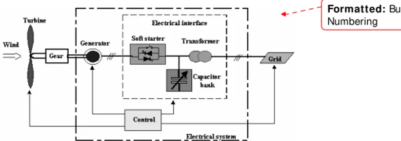
The electrical system of a grid connected wind turbine includes all components for converting mechanical power into electrical power as well as the auxiliary electric aggregates (the yaw system, the cooling system, the ventilation system), the control and supervisory systems. Fig. 1 illustrates the main components of the electrical system of a wind turbine connected to a grid.
Fig. 1. Block diagram of wind turbine connected to a grid with one type of electrical interface. The scheme comprises the wind turbine rotor, linked via a gearbox to a generator, which through an electrical interface is connected to the grid. A control system is necessary to assure a proper operation of the wind turbine under all conditions. Different configurations of the electrical interface exist. One typical solution contains a soft-starter, a capacitor
bank and a transformer. The transformer transforms the generator voltage to a higher voltage to the grid. The electrical part of the wind turbine is in continuously development as well as the control strategies are becoming more sophisticated. It is obviously that the simulation of the entire wind energy conversion system is very important during the development of the new control strategies.
2. SIMULATION PLATFORM CONCEPT Simulation is the most important technique used today for evaluation of engineering solutions. In general different simulation tools exist to simulate power converters, generators, power systems, mechanical parts and aeroelastic behavior of wind turbines. No simulation tools can be stated to handle all issues in detail at the same time. Therefore developing improved electrical models, it is important that they can be used in the selected tools and the user knows what are inside the models. The tools should be used according to the focus area of the designer. Independent of tools, the structure of a complete simulation platform for wind turbine should be as shown in Fig. 2.
The main idea of this new simulation platform is to extend the ability of the existing wind turbine design tools to simulate the dynamic behavior of the wind turbines and the wind turbine grid interaction. The model database must be able to support the analysis of the interaction between the mechanical structure of the wind turbine and the electrical grid during different operational modes.
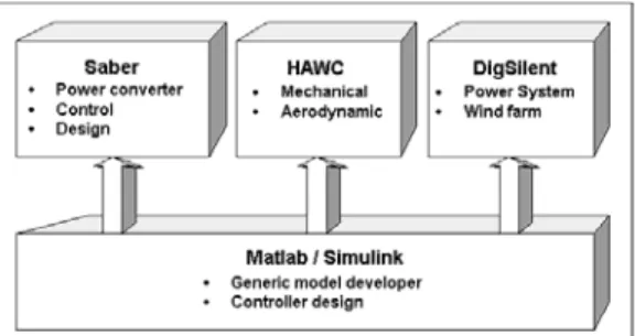
The models are the core of a simulation platform including the parameters or alternatively methods to determine the parameters based on measurements or data sheets. The new simulation platform contains models for four different simulation tools: HAWC, DigSilent, Saber and Matlab / Simulink. Fig. 3 illustrates the systems used in this new simulation platform.
Fig. 2. Structure of a complete simulation platform.
HAWC, an aeroelastic tool developed at RISØ National Laboratory, is used in the calculation of the dynamic loads on the structure of the wind turbine. It currently has focus on the aerodynamic and mechanical parts of the wind turbine, and it does not provide sufficient modeling details on the electrical system for assessing highly controllable wind turbines. DigSilent is a dedicated electrical power system simulation tool used for assessment of power quality and analysis of the wind turbine interaction with the grid. It has focus on the power system and not on the mechanical aspects of the wind turbine. Saber is a simulation tool used in circuit and systems power design including electrical, thermal, magnetic and mechanical components. However, this tool currently is not focused on wind turbine applications.
Fig. 3. Simulation tools used in simulation platform. Matlab / Simulink is used as a general model developer tool and also for validation of the models. The models are thus first checked in Matlab and then implemented in the other three tools.
The overall demands to all the models should be as follows:
• models should be open;
• parameters easy to determine (physical based most preferable) e.g. datasheets;
• simulation speed important;
• models based on common literature. Next improvement may be added;
• user friendly: documentation, reliable.
• easy to extend with extra features.
The idea of this new simulation platform is thus, to provide an extensive model database to perform simulations and performance studies of the wind turbines, both in continuous and fault operation. A long-term purpose is to use these models for a system optimization of the entire wind turbine, namely in a simultaneous optimization of the aerodynamic, mechanical, electrical and control systems over the whole range of wind speeds and grid characteristics.
3. MODELLING OF WIND ENERGY CONVERSION SYSTEMS
All the subsystems of a wind energy conversion system are interconnected and their functions are interdependent. In this way, as each subsystem has
Format t ed: Bullets and Numbering
Format t ed: Bullets and Numbering
specific characteristics, it results in a wide range of time constants and hence differential equations systems with high dynamic range of variables to solve using a simulator [Hansen et al, 2001]. A practical approach requires models with different detailing levels for each element. To model all elements of the system a multilevel model is needed. It can view a simulation environment at different abstraction levels. The main problem is the formulation of a simulation task at different modeling levels for different purposes:
• Component level: blocks of this type provide a small number of basic elements.
• Electric circuit level: blocks of this type describe the circuit topology – the interconnection between the component level.
• Functional level: the block is characterized by a “black box” with functionality to explain logical relations among the signals but says nothing about the implementation, for example: inverters, rectifiers, turbine, etc.
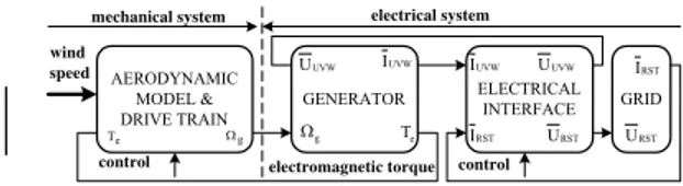
• Descriptive level: blocks of this type are characterized by a high degree of transparency. Based on this idea a wind energy conversion system can be modeled as shown in Fig. 4.
GENERATOR ELECTRICAL
INTERFACE GRID UVW
U IUVW
e T g
Ω
wind speed
electromagnetic torque control AERODYNAMIC
MODEL & DRIVE TRAIN
g
Ω
e T
UVW U UVW
I IRST
RST U RST
I URST
electrical system mechanical system
control
Fig. 4. Block diagram of a wind energy conversion system.
It is obviously that the models for electrical generators have an important role in the general model and especially for the electrical subsystem. Thus, the focus is currently on developing models for electrical generators and power converters e.g. soft-starter using Matlab / Simulink.
4. WIND TURBINES TOOLBOX Fig. 5 shows the current structure of the new Matlab/ Simulink Toolbox where a number of models have been developed.
Fig. 5. Structure of the new Matlab/Simulink Toolbox for wind turbine simulation
The first library “Simulink Blocks based Models” (Fig. 5)contains dynamic and steady-state models for electrical machines, modulation strategies for power converters and gear-box models. The following models for electrical machines are available: squirrel-cage induction machine, wound rotor induction machine, salient-poles synchronous machine and 3-phase transformer. The models are written in dq-reference frame and as ABC/abc models.
The second library “C S-Function based Models” contains the same blocks as the first one but all models are written in ‘C’ as Simulink Functions. The models with an S-Function implementation are very fast in the simulation. At least a factor of two in simulation speed is gained.
The third library “Power Converters Models” contains models for power converters based on switching functions. The following models are available at the moment: 3-phase diode bridge rectifier, voltage source converter (rectifier and inverter), starter for star connection and soft-starter for delta connection inside the machine windings.
The last library “Common blocks” contains: wind model, aerodynamic model for turbine, 3-phase distribution line, PI-controller and measurement blocks for active and reactive power.
5. MODELING ELECTRICAL MACHINES Much attention has been on modeling the electrical machine and its implementation. Dependent on the implementation method the simulation time can be significantly reduced.
All the models for electrical machines are written in state-space form:
[ ] [ ] [ ] [ ] [ ]
d i
A i B v
dt = ⋅ + ⋅ (1)
Furthermore, two modeling approaches have been studied with good results. The first approach uses the blocks available in Simulink as shown in Fig.6 and second approach is based on Simulink-Functions written in “C” language according with the Simulink format for this type of functions.
Format t ed: Bullets and
Numbering
Fig. 6. Simulink Model of squirrel-cage induction machine in dq rotor reference frame with constant parameters.
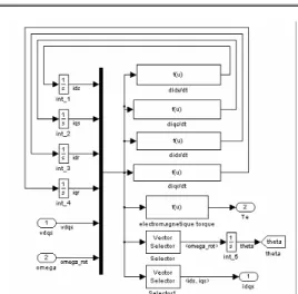
Using this approach - the state space form with currents as state variables - in modeling extra features, e.g. current displacement, saturation of magnetic path, can easy be added (Fig. 7).
Fig. 7. Simulink Model of squirrel-cage induction machine in dq rotor reference frame with current displacement.
Using Simulink Performance Tools Toolbox® both modeling approaches, with Simulink Blocks and with C S-Function, have been compared regarding the simulation speed [Iov et al, 2002]. The Simulink Profiler collects performance data while simulating a model and generates a report, called a simulation report [3]. The profile is useful to find out how much time Simulink spends executing each block from a model and hence where to focus the model optimization efforts.
The following pseudo-code summarizes the execution model on which the profiler is based.
Sim()
ModelInitialize().
ModelExecute() for t = tStart to tEnd
Output()
Update()
Integrate()
Compute states from derivs
EndIntegrate
Set time t = tNew. EndModelExecute
ModelTerminate
EndSim
According to this conceptual model, Simulink executes a Simulink model by invoking the required function zero, one, or more times, depending on the function and the model.
The profiler measures the time required to execute each invocation of these functions and generates a report at the end of the model that details how much time was spent in each function.
The considered models have been tested using Simulink Profiler for a simulation time of 0.3 s with a simulation step of 1 ms. Fig. 8 shows summary profiles for the functions invoked to simulate the entire models.
The functions recorded in Fig. 8 are:
• Sim - Simulate the model. This top-level function invokes the other functions required to simulate the model. The time spent in this function is the total time required to simulate the model.
• ModelInitialize - Set up the model for simulation.
• ModelExecute - Execute the model by invoking the output, update, integrate, etc., functions for each block at each time step from the start to the end of simulation.
• Output - Compute the outputs of a block at the current time step.
• Update - Update a block’s state at the current time step.
• Integrate - Compute a block’s continuous states by integrating the state derivatives at the current time step.
Fig. 8. Summary profile regarding the execution time for main functions during simulation.
The number of blocks used into a model has a big influence on the total simulation time. Function
Integrate is the most time consuming procedure during the simulation. When it is used one block to implement each differential equation, the total simulation time increases dramatically. However, using an S-function which implements all the differential equations from the considered dynamic system, the total simulation time is smaller than for a model, which uses multiple Integrator blocks. Moreover, the numerical stability increases using a S-Function.
6. START-UP SEQUENCE FOR INDUCTION GENERATOR USING A SOFT-STARTER Using available blocks from the new Toolbox the start-up sequence for squirrel-cage induction generator with and without soft-starter has been performed. The start-up sequence with soft-starter is used in wind turbine applications to limit the in-rush current of the generator during connection to the grid. Usually the soft-starter is connected for 100-200 msec and then it is removed from the circuit. Due to the operation modes of the soft-starters with an R-L load an ABC/abc model of induction generator has been used for simulations.
A. ABC/abc Model for Squirrel-Cage Induction Machine
Basic equations of the machine (assuming sinusoidal MMF and negligible saturation and losses in core) are [4]:
[ ] [ ] [ ] [ ]
dV R I
dt
Ψ
= ⋅ + (2)
[ ] [ ] [ ]
Ψ = L ⋅ I (3)where:
[ ] [
]
tA B C a b c
V = v v v v v v
- are the voltages applied to each stator and rotor phases;
[ ] [
]
tA B C a b c
I = i i i i i i
- are the currents in each stator and rotor phases;
[ ] [
]
tA B C a b c
Ψ = ϕ ϕ ϕ ϕ ϕ ϕ
- are the fluxes linked with each stator and rotor phases.
From (2) and (3) results:
[ ] [ ] [ ] [ ] [ ] [ ] [ ]
1 1d I d L
L R I L V
dt dt
− ⎧⎪ ⎫⎪ −
= ⋅ −⎨ − ⎬⋅ + ⋅
⎪ ⎪
⎩ ⎭ (4)
Most terms of the inductance matrix are functions of rotor position θ. Taking this into account:
[ ]
[ ]
[ ]
r
d L d L d d L
dt d dt d
θ
= ⋅ = ⋅ω
θ θ (5)
where ωris the rotor speed. Grouping (4) and (5) results:
[ ] [ ] [ ]
1[ ] [ ] [ ] [ ]
1r
d I d L
L R I L V
dt d
− ⎧⎪ ⎫⎪ −
= ⋅ −⎨ − ω ⋅ θ ⎬⋅ + ⋅
⎪ ⎪
⎩ ⎭ (6)
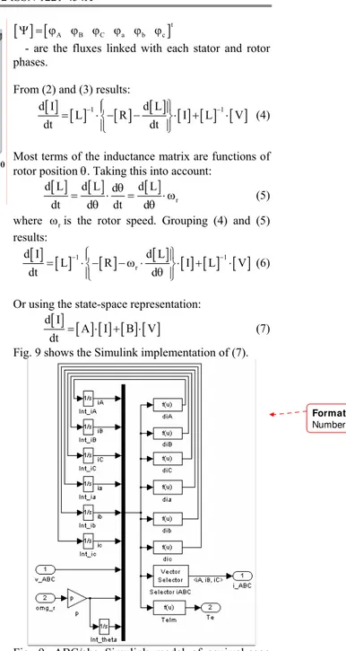
Or using the state-space representation:
[ ] [ ] [ ] [ ] [ ]
d IA I B V
dt = ⋅ + ⋅ (7)
Fig. 9 shows the Simulink implementation of (7).
Fig. 9. ABC/abc Simulink model of squirrel-cage induction generator.
B. Soft-Starter Model
The fully controlled topology with a wye-connected load (e.g. induction machine) is shown in Fig. 10.
Fig. 10. Fully controlled topology for soft-starter with wye-connected load: electrical diagram and electrical model using switching functions. Switching functions Sw_A, Sw_B, and Sw_C can be introduced for thyristors and defined as equal to one when a given thyristor is conducting and equal to zero otherwise.
It can be easily demonstrated that the output voltages of the AC controller are given by:
a wA wB wC A
b wA wB wC B
C
c wA wB wC
v 1 S S S v
v S S S v
2 v
v S S S
− −
⎡ ⎤ ⎡ ⎤ ⎡ ⎤
⎢ ⎥= ⋅ −⎢ − ⎥⋅ ⎢ ⎥
⎢ ⎥ ⎢− − ⎥ ⎢ ⎥⎣ ⎦
⎣ ⎦ ⎣ ⎦
(8) where:
[
]
Ta b c
v v v - are the output voltages;
[
]
TA B C
v v v - are the input voltages; SwA SwB SwC- are the switching functions.
Since the induction machine can be seen as an R-L load, two modes of operation can be defined for a soft-starter:
• Mode 1: ϕ ≤ α < αf lim - two or three thyristors conducting;
• Mode 3: o
lim f 150
α ≤ α < - none or two thyristors conducting.
where:ϕ - phase angle,αf- firing angle for soft-starter and αlim- limit angle.
Fig. 11 illustrates the Simulink model of the soft-starter:
Fig. 11. Simulink implementation of soft-starter with wye-connected load.
The switching functions are calculated based on firing angle and phase currents.
C. Simulation results
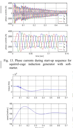
The start-up sequence for a 1.7 MW squirrel-cage induction generator with and without soft-starter, with parameters from [Krause et al, 1995], has been simulated. The soft-starter is connected close to synchronous speed for 130 msec and then it is removed from circuit.
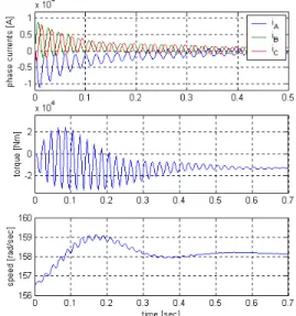
The phase currents, electromagnetic torque and rotor speed without soft-starter are shown in Fig. 12. It can be observed the high values of the in-rush currents around 6 times bigger than the rated current and the high oscillations in the electromagnetic torque and speed.
Fig. 12. Phase currents, electromagnetic torque and rotor speed during direct start-up sequence for squirrel-cage induction generator.
Fig. 13. Phase currents during start-up sequence for squirrel-cage induction generator with soft-starter.
Fig. 14. Electromagnetic torque and speed during start-up sequence of squirrel-cage induction generator with soft-starter.
Using a soft-starter for the start-up sequence, the electromagnetic torque is diminished and the
oscillations present in rotor speed without a soft-starter are eliminated.
7. CONCLUSIONS
This paper presents a new Matlab/Simulink Toolbox for wind power applications as a general developer tool in a simulation platform dedicated to model, optimize and design wind turbines. It is shown the structure of the toolbox and how the electrical machines are implemented. Some aspects regarding the simulation speed for the considered modeling approaches are also presented. The ABC/abc induction machine model and the soft-starter modeling are treated. Finally, simulation results for start-up sequence without and with soft-starter are shown.
8. REFERENCES
L. H. Hansen, F. Blaabjerg, H. C. Christensen, U. Lindhart, P. Hauge Madsen - Generator and Power Electronics Technology for Wind Turbines. Proceed. of IECON’2001, 2001, pp. 2000-2005;
F. Iov, F. Blaabjerg, A.D. Hansen, P.E. Sørensen-
Comparative Study of Different Implementations for Induction Machine Model in Matlab/Simulink for Wind Turbine Simulations, digest for COMPEL 2002, (accepted)
*** - Simulink – Dynamic System Simulation for Matlab – Using Simulink, The Mathworks Inc.; C. Goldemberg, A. de Arruda Penteado –
Improvements on the inductance matrix inversion simplifying the use of the ABC/abc induction machine model, pp. 422-424;
A.M. Trzynadlowski – Introduction to Modern Power Electronics, J. Wiley &Sons., 1998, ISBN 0-471-15303-6;
P. C. Krause, O. Wasynczuk, S. D. Sudhoff –
Analysis of Electric Machinery, IEEE Press 1995, ISBN 0-7803-1101-9;
Format t ed: Bullets and Numbering