HIGH SPEED BUTTERFLY
ARCHITECTURE FOR CIRCULAR
CONVOLUTION USING FNT WITH
PARTIAL PRODUCT MULTIPLIER
HEMALATHA BANDARI M.TECH (DECS)
ALAHARI RADHIKA M.TECH(VLSI), Asst Professor of ECE
SAKE POTHALAIAH M.E (ECE), Asst Professor of ECE
Dr.K ASHOK BABU Professor & HOD of (ECE)
SRI INDU COLLEGE OF ENGG&TECHNOLOGY (Affiliated to JNTU, Hyderabad) Ibrahimpatnam
Hyderabad, Andhra Pradesh, India -501510.
Abstract— This paper presents high speed butterfly architecture for circular convolution based on FNT using partial product multipliers. FNT is ideally suited to digital computation requiring the order of N log N additions, subtractions and bit shifts, but no multiplications. In addition to being efficient, the FNT implementation is exact with no round off errors. Binary arithmetic permits the exact computation of FNT. This technique involves arithmetic in a binary code corresponding to the simplest one of a set of code translations from the normal binary representation of each integer in the ring of integer. In the first stage normal binary numbers are converted into their diminished-1 representation using code conversion (CC). Then butterfly operation (BO) is carried out to perform FNT and IFNT where the point wise multiplication is performed using modulo 2n+1 partial product multipliers. Thus modulo 2n+1 additions are avoided in the final stages of FNT and IFNT and hence execution delay is reduced compared to circular convolution done with FFT and DFT. This architecture has better throughput and involves less hardware complexity.
Keywords—FNT, code conversion, butterfly operation, Diminished-1 representation, partial product multiplier.
I. INTRODUCTION
A direct implementation of convolution requires N multiplications, where N is the length of the sequence. In practice, direct convolution is used for short length convolutions, because for long convolutions, the computation involved may be excessive. To compute the convolution of two finite sequences efficiently DFT with FFT can be used. In FFT, most of the computation time is taken in computing two transforms and one inverse transform i.e., it requires (N/2) log2 (N/2) complex multiplications, in addition it introduces rounding and truncation errors, thus deteriorating SNR. Therefore Number Theory Transform (NTT) is used, in which all the arithmetic operations are performed modulo m and the results are exact without rounding errors.
When the modulus in NTT is a Fermat number, Ft=2 b
+1, where b=2t and t is a positive integer. The multiplication in FNT and IFNT can be converted into bit shifts when the transform kernel is 2 or its integer power. Most of the convolution architectures based on FNT are implemented for the operands in the diminished-1 representation. Thus CC stage which converts the normal binary numbers into their diminished-1 representation is compulsory. BO stage includes Arithmetic operations like modulo 2n+1 negation, addition, subtraction, multiplication which are in diminished-1 number system.
II. NUMBER THEORY TRANSFORM
The number theoretic transforms are defined over a finite ring of integers and are operated in modulo arithmetic. In this ring, using transforms like the DFT, the circular convolution can be performed very efficiently and without any round off errors. The NTT can be represented as the following equations:
N-1 X(t) = ∑ x(n)αnk
mod M k=0,…,N-1 (1) n=0
N-1
X(n) = N-1 ∑ x(n) α-nkmod M n=0,…,N-1 (2) n=0
Three constraints to use the NTT to implement circular convolution efficiently are:
1. N should be highly composite so that the NTT may have a fast algorithm, and it should be large enough for application to long sequence length.
2. Multiplication by powers of α should be a simple operation. If α and its power have a simple binary representation, then this multiplication reduces to bit shift.
3. In order to facilitate arithmetic modulo M, M should also have a very few bit binary representation.
In the ring of integers modulo M, conventional integers can be unambiguously represented if their absolute value is less than half of M. If the input integer sequences x[n] and h[n] are so scaled that |y[n]| never exceed M/2, we would get the same results by implementing convolution in the ring of integers modulo M as that obtained with normal convolution.
Let F = p1r1p2r2. . . .plrl be the prime factorization of F. since α is of order N, we have αN = 1 (mod F) which implies
αN
= 1 (mod pi ri
) i = 1,2,….,l. (3) If the transform matrix T is to be non singular, no two rows of T can be the same, which implies
αp ≠ αp(mod pi ri
) i = 1,….,l, p≠q (4) 0≤p, q≤N-1
It implies that α should be of order N with respect to each prime power factor piri of F, i.e., N is the least positive
integer such that
αN = 1 (mod p
iri) i = 1,2,….,l. (5)
If α is of order less than N with respect to any moduli piri , then T would be singular with respect to that modulus
and for N-1 to exist, N should be relatively prime to F, i.e., pi should not be a factor of N.
III. FERMAT NUMBER TRANSFORM
For number theoretic transforms to be more attractive in comparison with FFT for implementing convolution, they should be computationally efficient. There are three points to be considered. First, N should be highly composite (power of 2) for a fast FFT type algorithm to exist. Second, since complex multiplications take most of the computational effort in calculating the FFT, it is important that the multiplication by powers of α be a simple operation. This is possible if the powers of α have very few bit binary representations (power of 2) where multiplication by a power of α reduces to a word shift. Third, in order to facilitate arithmetic modulo F,F should also have a very few bit binary representation. Therefore the first possibility is 2k; it has a prime factor 2 and maximum possible transform length is 1. For 2k-1, let k be a composite PQ, where P is prime. Then 2P-1 divides 2PQ-1 and the maximum possible length of the transform will be governed by the length possible for 2P-1. These numbers are known as Mersenne numbers, but thee numbers are not of much interest because 2P is not composite and therefore do not have fast FFT type computational algorithms to compute the transform. For 2k+1 (say k is odd), then 3 divides 2k+1and the largest possible transform length is 2. This k is even. Let k be s2t, where s is an odd integer. Then 22^t + 1 divides 2s2^t+1 and the length of the possible transform will be governed by the length possible for 2s^ t+1. Therefore , integers of the form 22^t + 1 are of interest. These numbers are known as Fermat numbers. Fermat numbers seems to be optimum i.e., transform length is interesting but word size is moderate. From the above discussion it is proposed to use Ft = 2b + 1, b = 2t, t being a positive integer, as good choices for
F. Ft is known as fth Fermat number. In the structure of FNT, it doesn’t need multipliers when doing transform,
modulo procedure a easy thing. The diminished-1 representation is easy to think. In a digital system, it is easiest to take the modulo of a number in the form of power of two.
IV. DIMINISHED-1 NUMBER SYSTEM
To represent all integers in the ring of integers modulo Ft requires b + 1 bits. The additional bit is required in
order to represent the number 2b = -1 mod Ft . In order to overcome the problem of performing binary arithmetic
with this additional bit, a modified binary number system is used to avoid additions and multiplications involving the additional bit, allows the additional bit to be only 1 when the number to be represented is 0. This can be achieved by subtracting 1 from the normal binary
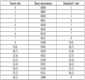
Representation of every integer in the ring. The normal representation and this Diminished-1 representation are indicated in the table:
Table 1. correspondence between normal and Diminished-1 representations(b=4)
Although the signal for which the FNT is being taken may be very small, its FNT coefficients may lie anywhere between 0 and Ft – 1. During various stages of computation each accumulation of the signal “overflows” many
times.. but still the end result of the convolution would be exact if the input signals are properly bounded. Example 1
Consider two sequences x = (2,-2,1,0) and h = (1,2,0,0), whose convolution is desired. From the overflow consideration, it is sufficient if we work modulo F2 = 17, where integer 2 is of order 8, N = 4, therefore 22 = 4 is an
α of order 4. The transformation matrix is given by
1 1 1 1 1 1 1 1 T = 1 4 42 43 = 1 4 -1 -4
1 42 44 46 1 -1 1 -1 1 43 46 49 1 -4 -1 4
1 1 1 1
= 1 4 16 13 (mod 17)
1 16 1 16
1 13 16 4
1 1 1 1 1 1 1 1 T = 1 4-1 4-2 4-3 = 4 1 -4 -1 4 1 4-2 4-4 4-6 1 -1 1 -1
1 4-3 4-6 4-9 1 4 -1 -4
1 1 1 1
= 13 1 13 16 4 (mod 17)
1 16 1 16
1 4 16 13
The transforms of x and h are given by
1 1 1 1 2 18
X = Tx = 1 4 16 13 15 78
1 16 1 16 1 = 243
1 13 16 4 0 213
1 = 5 (mod 17)
10 9
V. BINARY ARITHMETIC OPERATIONS MODULO FT
Negation
It can be seen from table 1 that each of the negative numbers (>2b-1) is the b-LSB complement of its positive counterpart. Thus with this system the negative of a nonzero number in diminished-1 representation is the complement of its LSB’s. Denoting the LSBS complement by an over bar, this can be shown as follows:
___
A-1 = 2b-1- (A-1) = 2b-1- A-1 = (-A) - 1.
If the MSB is 1, the negation is inhibited. Example 2
_ _ _ _ 13 = -4 mod 17 =0 0 0 1 1 Addition
To perform addition of two numbers represented as A-1 and B-1,
(A - 1) + (B - 1) = (A + B - 1) – 1 and thus (A + B - 1) = [(A - 1) + (B - 1)] + 1.
Since the (b + 1)th bit of the addends is used only to inhibit addition if an addend is zero, addition of nonzero
addends involves only the b-LSB’s. The above equations indicate that a 1 must be added to the sum of two diminished -1 numbers to provide a correct result. When a carry is generated from the b-bit sum, a residue reduction modulo Ft requires the subtraction of a 1 since 2b = -1mod Ft and no corrective addition is required. Thus
Example 3 Example 4
Add 10000 0 Add 10000 8 00100 5 01101 14 00100 5 10100 22 0 00100 Code translation
Using the above description of diminished -1 addition, we can present rules for the translation between a binary number B and its diminished -1 representation D.
From binary to diminished – 1 representation, perform a diminished -1 addition of B and the binary representation of 2b-1.
Example 5 Example 6
B = 01100 = 12 B = 00000 = 0 01111 01111 11011 01111 0 1 D = 01011 D = 10000
From Diminished – 1to binary representation, complement the MSB of D and add it to the b LSB’s
Example 7 Example 8
D = 01011 = 12 D= 10000 = 0 1 0 B = 01100 B = 00000 Subtraction
We can perform subtraction by negating the subtrahend and adding it to the minuend.
Example 9
Subtract 7 00110 -5 01011
2 10001
00001 Multiplication by powers of 2
In performing a multiplication if the multiplier or multiplicand are 0, as detected by the presence of a 1 in the (b+1)th bit, the multiplication is inhibited and the product is zero. To perform multiplication of diminished -1
numbers by powers of 2, let us consider the following: (A - 1) . 2 = (2A - 1) – 1
And thus
(2A - 1) = (A - 1) . 2 + 1.
Therefore, each multiplication by 2 involves a left shift ignoring the MSB, and a corrective addition of a 1. If the bit shifted out from the bth position is a zero, it is complemented and shifted into the LSB in order to
accomplish the addition of a 1. If this bit is a 1, a subtraction of 1 is also required to accomplish a residue reduction. With the corrective addition of +1, these cancel out and a 0 is ahifted into the LSB. Thus for each factor of 2, a left-circular shift of the b-LSB’s is required and the bit circulated into the LSB is complemented.
Example 10
8 x 11 = 23 x 11 = 2 x 2 x 2 x 11 = 88 = 3 mod 17
11 01010
2 x 11 00100 4 x 11 01001
In order to realize the full efficiency of the FNT, it is necessary to accomplish multiplication by powers of 2 by a single multibit shift.
General multiplication
The last operation required to carry out convolution with FNT is a general multiplication by any two integers modulo Ft. To perform a multiplication of the number A and B, represented as A – 1 and B – 1 in the diminished -1 number system,
(A – 1) (B – 1) = A.B – (A + B) + 1 = (A.B – 1) – (A+B-1) – 1.
Thus to carry out such an operation. Ignoring the MSB perform a binary multiplication of the diminished-1 representations of A and B, add this result to the b LSB’s of the diminished-1 addition of A and B and then perform a residue reduction by a diminished-1 subtraction of the b MSB’s from the b LSB’s. as discussed previously, if the MSB of either multiplier or multiplicand is 1, the multiplication is inhibited and the result is set to zero.
Example 11
Multiply 15
x 10 150 = 14 mod 17 Binary multiply 01110 diminished-1 add 01110 01001 01001
1110 10111
0111000
01111110 0
Binary add 00111 00111
10000101 ____ Residue reduction 0111
01100 1
01101 = 14 mod 17 An alternate multiplication technique can also be considered. Assuming that the numbers are determined to be non zero and a multiplication is required, a translation to normal binary coding is completed. Following a binary multiplication, a residue reduction by diminished-1 subtraction of the b MSB’s of the product from the b LSB’s is performed, the result is the desired. This is a realization of the equation (A.B – 1) = A.B – 1. Compared to above method, this method is simple and faster because translation from diminished-1 to binary will be simple and faster than general binary or diminished-1 addition. Where as first case involves translation of diminished -1 to binary representation, binary multiplication, residue reduction in diminished -1 notation, and multiplication by zero which is identical in various techniques. Therefore second method is preferred. Example 12 Multiply 15
x 10 150 = 14 mod 17 Translate 01110 binary multiply 01111 01010
1 11110
01111 11110
10010110
Translate 01001 ____ Residue reduction 0110 1 01100
01010
1
01101
VI. PROPOSED ARCHITECTURE
Important operations of the cyclic convolution based on FNT with the unity root 2 include the CCWA, the BOWA and the MPPM. The CC and the BO both consist of novel modulo 2n+1 4-2 compressors mainly which are composed of the 4-2 Compressors.
Code conversion operation
The CC converts normal binary numbers (NBCs) into their diminished-1 representation. It is the first stage in the FNT. Delay and area of CC of a 2n-bit NBC are no less than the ones of two n-bit carry propagation adders. To reduce the cost, we propose the CCWA that is performed by the modulo 2n+1 4-2 compressor. Let A
and B represent two operands whose widths are no more than 2n bits. We define two new variables: A = 2n A
H + AL
B = 2n BH + BL
_ M0 = (2
n
- 1) - AH = AH
_ M1 = (2
n
- 1) - BH = BH
_ M2 = (2
n
- 1) - BL = BL
If he subsequent operation of CC is modulo 2n+1 addition, assign AL, M0, BL and M1 to I0, I1, I2, I3 in the modulo 2n+1 4-2 compressor respectively. I0, I1, I2, I3 are defined as follows:
I0 = I0(n-1) I0(n-2) ….I01 I00
I1 = I1(n-1) I1(n-2) ….I11 I10
I2 = I2(n-1) I2(n-2) ….I21 I20 I3 = I3(n-1) I3(n-2) ….I31 I30
We obtain the sum vector H0* and carry vector H1* in the diminished-1 number system. The most significant bit ofH1* is complemented and connected back to its least significant bit.
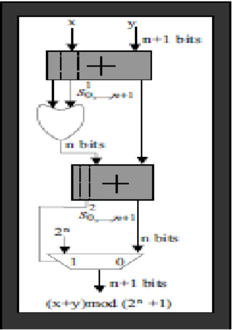
Modulo-2N+1 compressor:
A Modulo-2n+1 compressor is designed to convert four numbers to two-numbers. Thus the compressor could be regarded as the modulo-2n+1 adder since they perform same operation as counting two inputs of the compressor as one operand. That is the 4-2 compressor is designed as follows:
Fig 1: Modulo 2n
Fig 2: 4-2 compressor
CC, which is composed of modulo-2n +1 4-2 compressors, is constructed using 4-2 compressors as shown in figure (), the output is given by,
H0* = H0(n-1) H0(n-2) ….H01 H00
__ H1* = H1(n-2) ….H11 H10 H1(n-1)
The result of modulo 2n+1 addition of A* and B* is equal to the result of modulo 2n+1 addition of H0 * and
H1*. In this way, A and B are converted into their equivalent diminished-1 representations H0* and H1*.
Let
_ A* + B*2
n +1 , A
* 2
n +1 , A
*
- B* 2 n
+1 , and , A *
x 2i 2 n
+1 denote modulo 2 n
+1 addition, negation, subtraction and multiplication by the power of 2 respectively. The CCWA for subsequent modulo 2n +1 addition can be described as follows.
Fig 3: modulo-2n
+1 4-2 compressors
A* + B* = AL + M0 + BL+M1 2 n
+1 = H0 *
+ H1 *
2 n
+1
If the subsequent operation is modulo 2n+1 subtraction, we assign AL, M0, M2 and BH to I0, I1, I2, I3 respectively. Then H 0* and H 1* in the modulo 2n+1 4-2 compressor constitute the result of the CCWA. The conversion is described as follows:
_ A* - B* 2n+1 = A – B 2n+1 = A+B 2n+1
= H0 *
+ H1 *
2 n
+1
A series of modulo-2n+1 4-2 compressors put together can be called as code conversion stage. It uses the advantage of carry-save adder. After CCWA, we obtain the result consisting of two diminished-1 numbers. The result also includes the information of modulo 2n+1 addition or subtraction in the first stage of previous BO. Butterfly operation
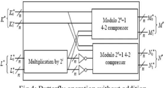
Each result consists of two diminished-1 values. The subsequent butterfly operation involves four operands. The proposed BOWA involves two modulo 2n+1 4-2 compressors, a multiplier and some inverters as shown in Fig 4.
The multiplication by an integer power of 2 in the diminished-1 number system in the BOWA is trivial and can be performed by left shifting the low-order n-i bits of the number by i bit positions then inversing and circulating the high order i bits into the i least significant bit positions.
Fig 4: Butterfly operation without addition
Thus the BOWA can be performed without the carry-propagation chain so as to reduce the delay and the area obviously. K*, L*, M*, N* are corresponding to two inputs and two outputs of previous BO in the diminished-1 number
M* = M0* + M1* 2n+1 = K0* + K1* + L0* x 2t +L1* x 2t 2n+1 = K* + L* x 2t 2n+1
N* = N0* + N1* 2n+1 = K0* + K1* - L0* x 2t - L1* x 2t 2n+1
= K* - L* x 2t 2n+1
____ = K* + L* x 2t 2n+1
Where K*= K0 *
+ K1 *
2 n
+1, L* = L0 *
+ L1 *
2 n
+1 Modulo 2n +1 partial product multiplier (MPPM)
The result obtained at the final-stage of BOWA is given at the input of a modulo 2n + 1 adder in order to accept these two summands and produce the required product in the diminished-1representation.In the proposed butterfly architecture for circular convolution based on FNT, the BO can accept four operands in the diminished-1 number system. Every point wise multiplication only needs to produce two partial products rather than one product. The operation can be accomplished by taking away the final modulo 2n+1 adder of two partial products in the multiplier. Thus the final modulo 2n+1 adder is omitted and the modulo 2n+1 partial product multiplier is employed to save the delay and the area.
Fig 6: Architecture of FNT operator Algorithm Approach
The Fermat transform for the two sequences are calculated parallel and then the product of the two transformed sequences is found, to this Inverse Fermat number transform is found.
Fig 7: Architecture for circular convolution based on FNT
It includes the FNTs, the point wise multiplication and the IFNT mainly. FNTs of two input sequences {ai} and
{bi} produce two sequences {Ai} and {Bi} (i=1,2, …N-1). Sequences { Ai } and { Bi } are sent to N MPPMs to
accomplish the point wise multiplication and produce N pairs of partial products. Then the IFNT of the partial products are performed to produce the resulting sequence {pi} of the cyclic convolution. In the architecture, the
radix-2 decimation-in-time (DIT) algorithm which is by far the most widely used algorithm is employed to perform the FNT and the IFNT. Commutators in are used to adjust the operand order of every stage of FNT and IFNT according to the radix-2 DIT algorithm.
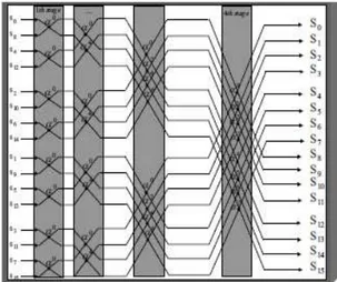
Fig 8: Parallel FNT structure for (Ft = 2 8
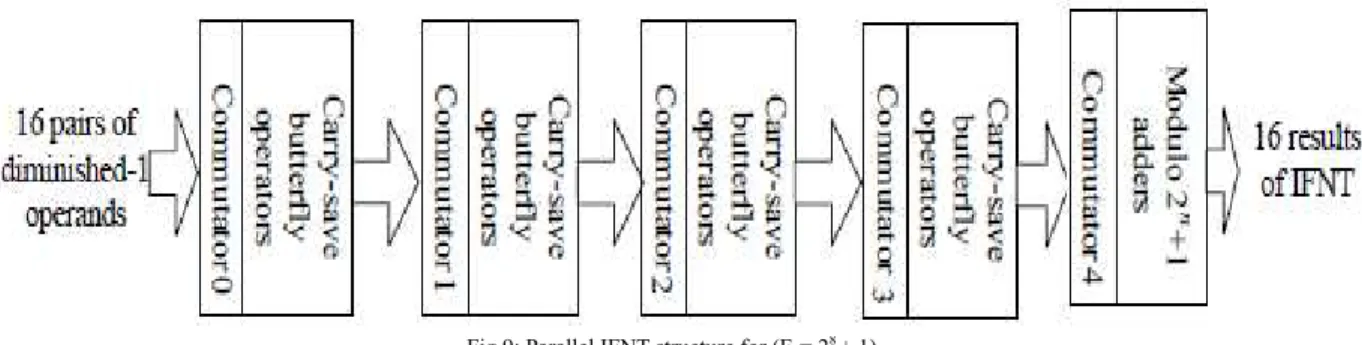
Fig 9: Parallel IFNT structure for (Ft = 28 + 1)
The efficient FNT structure involves log2N+1 stages of operations. The original operands are converted into the
diminished-1 representation in the CCWA stage, containing the information of modulo 2n+1 addition or subtraction in the first butterfly operation stage of the previous FNT structure. Then the results are sent to the next stage of BOWA. After log2N-1stages of BOWAs, the results composed of two diminished-1 operands are
obtained. The final stage of FNT consists of modulo 2n+1 carry-propagation adders which are used to evaluate the final results in the diminished-1 representation. The CCWA stage, the BOWA stage and the modulo 2n+1 addition stage in the FNT involves N/2 couples of code conversions including the information of modulo 2n +1 addition and subtraction, N/2 butterfly operations and N/2 couple of modulo 2n+1 additions respectively.
VII. RELATED WORKS
Fermat number transform, which is based on number theory transform, requires less computations and less hard ware design, so this FNT can be used in digital computation, its application to different functions as filtering or correlation process, can provide real benefits for low computational complexity. It is used in signal
convolution, image correlation and image filtering, since it does not have any round off errors. VIII. SIMULATION RESULTS
code conversion stage results
Fig 10 : simulation response of code conversion stage.
This is the first stage in FNT section. It will convert 16-bit normal binary operands into 8-bit diminished-1 operands. It uses the concept of carry save addition and carry propagation addition. The figure shown in 4.8 is the code-conversion stage outputs for different input sets.
Butterfly operation stage-1
Now the outputs of two FNT sections are given to the inputs of modulo-Partial Product Multipliers.
Fig 11. Simulation response of Butterfly-operation stage 1
Modulo-Partial Product Multiplier
This block will multiply two FNT output sequences. The obtained result is taken as 17-bit by considering the extreme case. The result never becomes 18-bit. Figure 4.10 shows Modulo-Partial Product Multiplier result
The IFNT block consists of same blocks as present in FNT structure except code-conversion stage because the result is already in diminished -1 form.
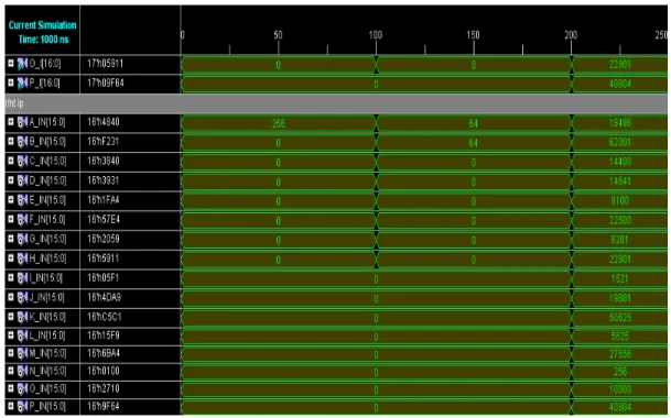
Fig 13. Simulation response of IFNT inputs
IFNT outputs
The output is obtained in diminished-1 form. To convert into normal form we add 1 to the result obtained at IFNT output section. IFNT output section is shown in figure 4.13.
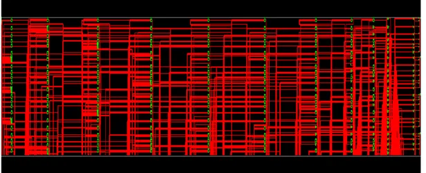
Fig 3.18 Technological View OF FNT_IFNT
REFERENCES
1. Jian Zhang and Shoguo Li,”High speed parallel architecture for cyclic convolution based on FNT” IEEE Trans. Institute of micro electronics, pp. 199–204, Sept. 2009.
2. Lawrence M. Leibowitz,”A Simplified binary arithmetic for the fermat number transform,” IEEE Trans Acoustics, speech, and signal processing, pp. 356–359, Oct. 1976.
3. Ramesh C. Agarwal and Charles S. Burrus “ Fast convolution using number transforms with applications to digital filtering,” IEEE trans. Acoustics, 4. Curiger,“VLSI Architectures for Computations in Finite Rings and Fields,” PhD thesis, Swiss Federal Inst. of Technology (ETH), Zurich, 1993. 5. Tyagi,”A Reduced-Area Scheme for Carry-Select Adders,” IEEE Trans. Computers, vol. 42, no. 10, Oct. 1993.
6. Cheng, K.K. Parhi, “Hardware efficient fast DCT based on novel cyclic convolution structures”, IEEE Trans. Signal processing, 2006, 54(11), pp. 4419-4434.
7. H.C. Chen, J.I. Guo, T.S Chang, et al., “A memory efficient realization of cyclic convolution and its application to discrete cosine transform”, IEEE Trans.Circuit and system for video technology, 2005,15(3), pp. 445-453.
8. J . M. Pollard, “The fast Fourier transform in a finite field,” Math. Compul., vol. 25, pp. 365-374, Apr. 1971.
9. V. Paliouras and T. Stouraitis, “Novel High-Radix Residue Number System Multipliers and Adders,” IEEE Int'l Symp. Circuits and Systems VLSI (ISCAS '99), pp. 451-454, 1999.
10. R.P. Brent and H.T. Kung, “A Regular Layout for Parallel Adders,” IEEE Trans. Computers, vol. 31, no. 3, pp. 260-264, Mar. 1982. 11. Soudris, D.; Paliouras, V.; Stouraitis, T.; Skavantzos, A.; Goutis, C ” system design of full adder-based architectures for convolution,” IEEE
Trans.Acoustics,speech, and signal processing, vol. 1,ICASSP-93.pp. 389-392,1993.
12. Arambepola.B “VLSI circuit architectures for Fermat number arithmetic in DSP applications”signal processing applications of finite field mathematics, IEE colloquium, pp. 5/1-5/7,1989.
13. Mark E. Dodge ; Eugene S. McVey ; IBM, Manassas, Va. ”A microcode implementation of a fermat number transform for fast digital convolution”,IEEE Conference on, decision and control including the symposium on adaptive processes,vol. 19, pp.1235-1241,April 1980. 14. Truong, T.K. ; Reed, I.S. ; Yeh, C.-S. ; Shao, H.M.” A parallel architecture for digital filtering using fermat number transforms”,IEEE Trans.
Computers, vol. C-32,pp. 874-877,21 Aug 2006.
15. Nussbaumer, H.J.; Compagie IBM France, centre d’Etude et Recherches 06610 La Gaude, France ”Complex convolutions via fermat number transforms,” IBM Journal of Research and development,vol. 20, pp. 282-284, 6 April 2010.
16. C. Efstathiou, H. Vergos, G. Dimitrakopoulos, et al., “Efficient diminished-1 modulo 2n + 1 multipliers”, IEEE Trans. Computers, 2005, 54(4), pp. 491-496.
17. M. Nagamatsu, S. Tanaka, J. Mori, et. al. “15-ns 32 ×32-b CMOS multiplier with an improved parallel structure”, IEEE Journal of Solid-State Circuits, 1990,25(2), pp. 494-497.
18. T. Toivonen, J. Heikkila, “Video filtering with fermat number theoretic transforms using residue number system”, IEEE Trans. circuits and systems for video technology, 2006, 16(1), pp. 92-101.
AUTHOR BIOGRAPHIES:
I B. HEMA LATHA graduated from the Dept. of ECE in G.Narayanamma Institute of Science and technology in 2007 at Hyderabad, final Year M.TECH (DECS) from Sri Indu College of Engg. & Technology and published one International conference and National Conference and interested Research in DSP and Image Processing.
Obtained his M.E. degree from the department ECE, University College of Engineering, OU in 2008. He is Working as Assoc. Prof, Department of ECE, Sri Indu College of Engg. & Tech. He has published 6 research papers in international conferences, his interests are in Ad hoc wireless networks works, Image Processing, Control System and Bio Medical Signal Processing.