1 INTRODUCTION
Energy efficiency in buildings is mandatory but the occupants’ thermal comfort must be preserved. In fact, buildings consume more energy than any other sector of the economy, about 40% of the total energy consumed in UE (Eurostat 2010). Nevertheless, thermal comfort improves morale and productivity as well as health and safety. In uncomfortable hot and cold working environments, its significance is related to unsafe working behaviours due to deterio-ration of people's ability to make decisions and/or perform manual tasks (Singh 1996). Currently, there are two common approaches on thermal comfort re-search: static heat balance models of human body based on laboratory studies and adaptive models based on field studies. The most known static heat balance model is the lab-based Predicted Mean Vote (PMV) and Predicted Percentage of Dissatisfied people (PPD) method developed by Fanger (1970). This model is described as a function of four envi-ronmental variables (air temperature, mean radiant temperature, air relative humidity and air velocity) and two personal variables (activity and clothing level of the occupants). A hydronic radiant floor heating (RFH) system heats the floor by circulating water through tubing that is laid inside or underneath the floor in a continuous series of loops. As the fluid circulates through the system it passes through a heat source like a boiler or a heat pump, where it is heat-ed. The water temperature is usually low (30ºC to 40ºC) and the fluid is responsible of transferring the
heat to the floor that emits the energy to the envi-ronment mainly through radiation and less by natural convection. The transmitting circuit departs from the supply and return manifold where the flow is regu-lated and driven depending on the thermal require-ments. The flow rate is regulated by a single pump and a general solenoid valve for each division in or-der to individually control the heat release at each location. The main advantage of a RFH system is to make possible to obtain an optimum temperature profile, in fact near the ideal heating. A RFH system increases the efficiency of heat generators (boiler and heat pump) since it uses low temperature water for operation. It is compatible with solar thermal col-lectors, which significantly increases its efficiency. The operating temperature required may be obtained at a lower air temperature, causing the air to be per-ceived by the occupant to have a higher quality as stated by Fanger et al. (1998). It is a versatile system that can work for both heating and cooling (Olesen 2002). The disadvantages of using RFH systems are few. It has a challenging installation in finished buildings, being preferable to install RFH systems during the building construction. The response time is slower than the majority of heating systems, and this time will depend heavily on the floor finish. For example, wooden floors response time will be great-er than for a tile floor (Martins 2011). Heating equipments are typically controlled by a wall ther-mostat. These systems requires a frequent adjust-ment of thermostats set-point in order to obtain
Experimental evaluation of an innovative command for hydronic radiant
heating floors
P.D. Silva, P.D. Gaspar, G. Batista & C. Domingues
University of Beira Interior, Faculty of Engineering, Covilhã, Portugal
ABSTRACT: This paper presents the results of an innovative control, regulation and command system for hydronic radiant floors, more flexible and efficient that guarantees a better thermal comfort to the user and simultaneously improves the energy efficiency of this type of heating system. The control algorithm is based on the calculation of PMV (Predicted Mean Vote) index as defined on Thermal Comfort Standard ISO 7730. To improve energy efficiency, the control algorithm was implemented on a microcontroller system that fea-tures wireless communication with sensors modules powered by energy harvesting systems. The experimental tests were performed in a hydraulic underfloor built into a laboratorial climatic chamber. The results show that for a water inlet of 35 ºC, the controller turn the valve on/off less than other control systems in order to adjust the PMV while maintaining the floor surface temperature less than 29 ºC as recommended by international standards.
thermal comfort as it depends on other factors than just the air temperature, such as, the air humidity, radiant temperature, among others. Currently, micro-electronic models are replacing the conventional wall thermostats, allowing to set the heating and cooling equipment at different temperature levels depending on daytime. This kind of modes perform numerical calculations and act accordingly to a con-trol algorithm that uses sensors information to com-mand the actuators. This paper presents the experi-mental results of a RFH which control is based on several variables that allow a better interpretation of the environment by the controller. The control algo-rithm was developed by Batista et al. (2013) and is based on the calculation of PMV index defined in ISO 7730 (2005) which will allow the controller to command the actuators in order to achieve a comfort category A, as set by that standard.
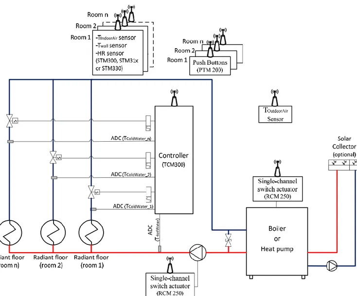
2 CONTROL SYSTEM CONFIGURATION The control system is designed to regulate the tem-perature of the radiant floor in order to provide
thermal comfort to the occupants. Thus, the device calculates regularly the PMV index in each room, using data from the temperature and humidity sen-sors installed in each room. Based on this index, the system will control the valves aperture and the pump operation, consequently providing more or less heat to the floor to achieve a thermal comfort near the range of class A category (-0.2 < PMV < 0.2). A di-agram of the general operation of this system is shown in Figure 1. The control system details can be found in Batista et al. (2013). The control system us-es the calculation method for the surface temperature of a RFH system proposed by Jin et al. (2010). The calculation method results are in agreement with the experimental and numerical values available in the literature for this system. Afterwards, the PMV in-dex calculation procedure within the control system follows the equations provided by Fanger et al. (1998). Thus, the controller calculates regularly the PMV index value for each room to command cor-rectly the solenoid valve that allows the passage of hot water to the respective room floor circuit.
3 EXPERIMENTAL SETUP
An experimental setup consisting of a climate cham-ber in which a radiant hydraulic floor was inserted was used to evaluate the real performance of the control algorithm. The climatic chamber, with 1200×1000×1420 mm3, shown in Figure 2a) was al-ready used in previous works (e.g. see Pires et al. 2013). The exterior and interior walls of the cham-ber, with 19 mm thickness, are made of water re-sistant MDF (medium density fiberboard). The insu-lation is provided by extruded polystyrene boards (150 mm thickness). The chamber was connected to an air conditioning system to control temperature and humidity. Type K thermocouples were distribut-ed inside the chamber to provide surface temperature measurements. The hydraulic radiant floor consists of four distinct parts: thermal insulation, piping, mortar and surface coating. The base of the radiant floor was made by extruded polystyrene board with 30 mm thickness. The working fluid piping (11 mm ext. diameter) was disposed over the insulation layer. A 24 mm thick layer of mortar reinforced with tex-tile fibers to control shrinkage covered the entire hy-draulic circuit. A polythene film layer 1 mm thick and a wood veneer 7 mm thick were placed over the mortar layer. The working fluid is water heated in a 1.5 kW thermostatic bath. The thermal comfort measurements are performed through an air velocity probe, an operative temperature probe, an air
tem-perature probe and globe temtem-perature probe (WBGT - Wet Bulb Globe Temperature). This equipment was placed on the surface of the radiant floor, using a tripod that supports various sensors as shown in Figure 2a). The operative temperature sensor was set at 30º from vertical to simulate a seated user. The general appearance of the controller (TCM300 wire-less system module) and push button (PTM200 with electrodynamic energy harvesting) are shown in Fig-ure 2b). The temperatFig-ure and relative humidity sen-sors are connected to the wireless transmit-ter/receiver modules (STM300, STM31x and STM330) that capture energy from either local illu-minance, thermal or motion energy are shown in Figure 2c).
4 RESULTS AND DISCUSSION
Several tests were performed to characterize the be-haviour of the controller in obtaining the thermal comfort conditions inside the climate chamber by regulating the inlet temperature of the water in the radiant floor. Before each experimental test, the cli-matic chamber was stabilized with the aid of an air conditioning system. The stabilization of the exper-imental setup comprised the thermal stabilization of the floor surface, interior walls surface and air tem-perature. To this end, air at about 17.5 °C (Ta.in) was
blown into the climatic chamber while the radiant floor was maintained on with a constant temperature circulating water of 20 °C.
Figure 2. (a) Overview of the climatic chamber with all sensors; (b) Detail of the controller (TCM300) and push button (PTM210); (c) Detail of the energy harvesting sensor (STM330) located on the climatic chamber walls.
Accordingly, the stabilization of the climatic chamber took place over a period of 3 hours and thereafter a PMV index equal to 0.6 was obtained corresponding to a thermal environment class C. The test was initiated by actuating the control device af-ter chamber stabilization. As the device detects a low PMV value, activates the valve allowing the wa-ter to go through the radiant floor at a preselected constant temperature. In this case study, the water temperature was set to 35 ºC. From this point, the controller will open or close the valve, as defined in the algorithm, until the value of the PMV index cal-culated by the controller is near zero (thermal com-fort). In this study also tested the operation of the push buttons by clicking twice to increase the tem-perature. Since other environmental parameters re-main, this action increases the PMV index.
Figure 3 shows the behaviour of operative temper-ature, To, air temperature, Ta, and globe temperature,
Tg, along the test. As a result of the floor heating
process, the growth of these quantities is similar to the increase of the temperature on the surface of the radiant floor promoted by the controller. This growth is seen during the first six hours of the test. After this period, the temperatures tend to stabilize as, again, a result of the action of the controller. As expected,
the operative temperature is between globe tempera-ture and air temperatempera-ture by considering the radiative effects.
The PMV index calculated based on measured values by the thermal comfort equipment is given in Figure 4. The controller calculates this index using the measured values of air temperature and relative humidity inside the climatic chamber from the wire-less and energy-harvesting sensor modules.
As shown in Figure 4, in the first two hours of the test PMV index has a significant growth. Subse-quently, it continues to increase but more gradually until reaching six hours of rehearsal. From this mo-ment the PMV index measured in the climatic chamber tends to stabilize near to 0.1, showing that there is a difference of 0.1 between the PMV value calculated by the controller and PMV index from the thermal comfort equipment. Note that the PMV be-haviour after twenty hours and fifteen minutes of the test is the result of pressing the push button to simu-late a heating requirement by the occupant of the space. This action results in an increase of the PMV index by 0.1 points. The action of the controller in the temperature of water circulating in the radiant floor is illustrated in Figure 5.
Figure 3. Operative temperature, To (), air temperature, Ta (), and globe temperature, Tg (), inside climatic chamber along the
test.
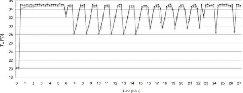
Figure 5. Radiant floor water inlet, Tw.in (), and outlet, Tw.out (), temperatures along the experimental test.
Figure 6. Temperature evolution at three point on the radiant floor surface (Legend: Tf.p1: ; Tf.p2: ; Tf.p3: ).
At the beginning of the test, as the controller de-tects a low value of the PMV index (-0.6), the device automatically actuates the valve allowing the water to circulate on the radiant floor at pre-set tempera-ture (35°C).The device keeps the valve open for about 6 hours until the PMV index is near zero. From this moment, the controller intermittently acti-vates the valve in order to guarantee the maintenance of thermal comfort category A (PMV between -0.2 and 0.2). The actuation of the push button of the controller, performed after twenty hours and fifteen minutes and above mentioned, does slightly increase the operation period of the valve in order to meet the requirement of demand for heat from the occupant corresponding to a PMV increase (see Fig. 4 and Fig. 5).
Figure 6 shows the evolution of the radiant floor surface temperature at three measurement points (Tf.p1, Tf.p2 and Tf.p3). As noted, the action of the
con-troller keeps the surface of the radiant floor constant throughout the heating process ensuring that the maximum allowable temperature is never exceeded.
5 CONCLUSIONS
The operation of an innovative solution to control a hydraulic underfloor heating system was experimen-tally evaluated in this work. The device uses a con-trol algorithm based on the calculation of PMV (Predicted Mean Vote) index as defined on Thermal Comfort Standard ISO 7730. This control algorithm was implemented on a controller featuring wireless communication with no battery sensors modules with energy harvesting systems. This devices set was tested in a hydraulic underfloor built into a laborato-rial climatic chamber. The experimental results show that with a water inlet of 35 ºC the controller turned the valve on/off barely in order to adjust the PMV index while maintaining the floor surface tempera-ture less than 29 ºC as recommended by international standards. This device ensures the thermal comfort conditions in various operation modes and has a proper response to heat requests from occupants. Thus, the developed algorithm allows a quick re-sponse from underfloor heating not exceeding the maximum floor temperature and keeping the envi-ronment within the A category of thermal comfort.
6 REFERENCES
Eurostat. Consumption of Energy - European energy statistics. Eurostat, European Commission.
Singh, J. 1996. Impact of indoor air pollution on health, com-fort and productivity of the occupants. Aerobiologia 12:127-121.
Fanger, P.O. 1970. Thermal comfort: analysis and applications
in environmental engineering. USA: McGraw-Hill.
Fanger, L., Clausen, G., Fanger, P.O. 1998. Impact of tempera-ture and humidity on the perception of IAQ. Indoor Air 8:90-80.
Olesen, B.W. 2002. Radiant floor heating in theory and prac-tice. ASHRAE Journal 44:26-19.
Martins, P.M. 2011. Hydraulic radiant floor analysis, Master Science Thesis. Portugal: University of Beira Interior. Batista, G., Gaspar, P.D., Silva, P.D. 2013. Control, regulation
and command system of hydronic radiant floors heating by wireless and energy harvesting sensors and actuators. Key
Engineering Materials 543:392-389.
ISO 7730. 2005. Ergonomics of the thermal environment —
Analytical determination and interpretation of thermal comfort using calculation of the PMV and PPD indices and local thermal comfort criteria. Int. Organization for
Stand-ardization: ISO.
Jin, X., Zhang, X., Luo, Y. 2010. A calculation method for the floor surface temp in RF system. Energy Buildings 42:1758-1753.
Pires L., Silva, P.D., Castro-Gomes, J.P. 2013. Experimental study of an innovative element for passive cooling of build-ings. Sustainable Energy Technologies and Assessments 4:35-29.