Printed version ISSN 0001-3765 / Online version ISSN 1678-2690 http://dx.doi.org/ 10.1590/0001-3765201820170144
www.scielo.br/aabc | www.fb.com/aabcjournal
Monitoring structures with optical fibers: infiltration detection
LILIANE R. MARCONCIN1
, ROBERTO D. MACHADO1
, LUIZ A. DE LACERDA1,2 and
MARKUS AUFLEGER3
1
Programa de Pós-Graduação em Métodos Numéricos para Engenharia, Centro de Estudos de Engenharia Civil/CESEC, Universidade Federal do Paraná, Centro Politécnico, s/n,
Jardim das Américas, Caixa Postal 19011, 81531-980 Curitiba, PR, Brazil 2
Institutos LACTEC, Bloco LAME, Centro Politécnico, s/n, Jardim das Américas, Caixa Postal 19067, 81531-980 Curitiba, PR, Brazil
3
Hydraulic Engineering Laboratory/Arbeitsbereich Wasserbau, University of Innsbruck, Technikerstrasse, 13 A-6020 Innsbruck, Austria
Manuscript received on March 7, 2017; accepted for publication on December 20, 2017
ABSTRACT
The use of sensors and optical fibers for monitoring structures is continuously growing. Strains, displacements, accelerations, temperatures are just a few of the monitoring possibilities. In the case of dam structures, concrete face rockfill dams constitute a type of structures where the monitoring of water infiltrations is of particular interest. In large structures of this type, opening of slab joints is a common effect of general strain distributions, but crack formation may also occur as a result of high compressive stresses, during and after the reservoir filling stage. In this context, this paper verifies, experimentally, the applicability and the response of a distributed fiber optic monitoring system in the identification of infiltration spots and its potential sizes. The experimental tests confirm the technical feasibility of detecting infiltrations, but did not show clear evidence of their sizes.
Key words: concrete face rockfill dam, infiltration, monitoring structures, optical fiber.
Correspondence to: Liliane do Rocio Marconcin E-mail: liliane.m@ufpr.br
INTRODUCTION
The general concern about safety of constructions has motivated researchers to make use of sensing technologies, such as optical fibers, for monitoring the health of structures.
Monitoring a structure involves measuring, evaluating and registry of data that describes
structural behavior. Thus, the constitution of a monitoring system comprises a net of sensors attached to the structure, connected to systems of
acquisition, storage and information processing (Assis 2007).
Through the continuous monitoring of structures it may be possible to take decisions and actions for minimizing material damage, avoiding environmental hazard and life loss.
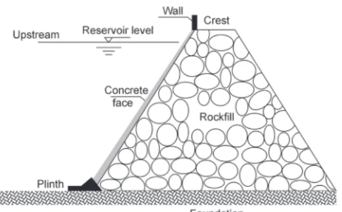
given structure can be extended through tests and monitoring that ensure its capability and safety. The operation costs of a monitoring system of structural health to the lifespan of the structure is lower than 1% of the structure expenses (Thomson 2013). The larger the structure or its importance, the greater the concern with its stability, behavior and security. Ranks in this category the dams, in particular, the concrete face rockfill dams. A concrete face rockfill dam is constituted by a main body, composed by rock blocks juxtaposed in compacted layers and a sealing slab at the upstream face (Figure 1).
The purpose of the slab is not structural, but to behave like a membrane that adapts itself to the displacements, and, therefore, is not subjected to bending stresses (Loriggio and Senem 2003). When the reservoir is filled, the rockfill bulk strains, and, especially for the bigger dams, due to increased displacements of the dam body, caused by hydrostatic pressure, fissures, cracks and openings of the joints may appear in the slabs of the concrete face. Hence, the water-flow through the bulk rises considerably, bringing up concern about the structure stability.
One way to detect infiltrations is through the use of optical fiber sensors, which started in Germany at the fifties (Johansson and Sjödahal 2004). Infiltration is detected by temperature measurements along the optical fibers. It is also possible, through this kind of monitoring, to observe the evolution of hydration heat of the mass concrete structures (Lacerda and Soares 2010). Several researchers (Johansson 1997), (Aufleger et al. 2007), (Hoepffner 2008), (Goltz 2011), (Aufleger et al. 2011), (Etzer et al. 2012), (Lew and Loh 2014) have been utilizing nowadays the optical fiber technology as a way to monitor infiltrations, temperature fields and strains in dams. One of the main advantages of the optical fiber sensors is the ability of measuring these magnitudes at several points with only one optical fiber (Ribeiro 2009).
Monitoring the structural integrity of dams is clearly important. In this context, this work is intended to show the capability of the distributed temperature optical fiber sensing technology for detecting pressured water infiltration through a membrane opening of different sizes. The experimental tests were carried out with cables placed at different distances from the infiltration spot.
FIBER OPTIC MONITORING
Optical fibers are glass filaments with a diameter comparable to a human hair, through which a luminous beam passes by consecutive reflections. It may be transmitted through large distances and with very low signal loss (Ribeiro 2009), (Zeni 2009).
According to the quantity of propagating modes, fiber optics can be classified as mono-mode and multi-mode. In the mono-mode fibers only one beam propagates itself, whereas multi-mode fibers can transmit hundreds of luminous beams (Ribeiro 2009).
Sensors are devices that show changes of behavior or properties when subjected to the action of a certain physical or chemical magnitude (Assis 2007). The optical sensor purpose is to retrieve measuring parameters, such as temperature, pressure, strain, and others, which is obtained by the beam light displacement (Ribeiro 2009).
By the time the discharged pulse reflex reaches the same wave length of the emitted wave, one gets a Rayleigh band or peak, which is the strongest returned signal. In the Rayleigh dispersion, photons maintain its original wave length and frequency, and do not lose energy, therefore able for being used for the measurement of optical loss (Bailey and Wright 2003).
The emitted light reflex can exist as a wave length that is a little above or below the incident wave. In the Brillouin wave, very similar to Rayleigh and also the Raman (the weakest one), there is a loss of energy of the photons, which is presented by the wavelength and frequency changes of the reflected beam, which also can sense the heat variations in the fiber.
In an experimental study developed by Imai and Feng (2012), Brillouin sensors applied to concrete prisms were able to detect, locate and quantify fissures in the prisms.
The Raman spectra is a sign used for temperature evaluation, composed by bands known as Stokes and anti-Stokes. The Stokes bands can deliver higher wave lengths than the emitted wave, and little heat sensibility. The anti-Stokes bands, with smaller wave lengths, exhibits great heat sensibility: the higher is the temperature, higher is the energy inside the band (Bailey and Wright 2003). This is the distributed sensing method employed in the tests performed and presented in the next sections.
Infiltrations can be detected from the temperature readings, which can be done by two alternative methods: Gradient Method or Passive, and the Heat Method or Active (Aufleger et al. 2007, 2011), (Etzer et al. 2012).
The Gradient Method can detect, locate and quantify infiltrations inside hydraulic structures, which are done by the natural occurrence of the gradients and temperature fluctuations between the water held in the reservoir and the dam bulk. In other words, this method requires a temperature As stated by the measurement principle, fiber
optic sensors are divided in intrinsic or extrinsic/ hybrids. The measurement point of the intrinsic sensors is located inside the optical fiber: the sensor is the fiber itself. The measurement point of the extrinsic sensors is located outside the optical fiber: the fiber just transports the information to the monitoring site (Ribeiro 1996).
The sensors depend on the transduction mechanism, which occurs through the intensity modulation, the wave length or the frequency, the polarization, and the guided radiation phase. They can be subdivided in intensity sensors and interferometric sensors (Ribeiro 1996). The intensity type sensors are generally built with multi-mode fibers. They are based on the intensity modulation or the wave length that relates light intensity loss with the optical fiber stress among its length (Bailey and Wright 2003). The interferometric sensors normally use mono-mode fibers and are based in mechanisms of polarity modulation, wave length and phase. Inside this classification one can find spectrometric sensors, which relates the light wave length to the parameter that is intended to be measured, and the phase type sensors, used to monitor physic phenomena, which applies to a wide range of optical phenomena (Bailey and Wright 2003).
Considering its application, fiber optic sensors can be classified as: located sensors, where measurement happens in a specific optical fiber segment; multiplexed sensors, obtained by the combination of individual sensors and used for verifying disturbances of the structure as a whole; and distributed sensors that measure and transmit data at the same time.
variation in the environment that surrounds and interacts with the optical fiber (Goltz 2011). The difficulty in applying this method in large or bulky structures is due to the fact that temperature gradients are only detected along large periods of time (Rocha 2011).
The Heating Method, in turn, can be used when there is not enough temperature gradient caused by the anomaly that needs to be detected. This technic allows detecting the water presence, its movement and the outflow regime, by the thermal response evaluation after extreme heat induction (Aufleger et al. 2007). Heat is added during a certain time gap, by an electric current – continuous or alternated, through copper wire distributed among the optic fiber, which constitutes a hybrid optic cable.
The method is based in the thermal response around the sensor, measured by the copper electric resistivity, and indicates if the cable is in a humid environment, partially saturated or completely saturated, and if there is an infiltration flow (Goltz 2011). In the absence of any infiltration around the cable, the temperature elevation is determined by conduction. The copper cable gets heated, transfers the heat to its walls, and the wall transfers the heat to the surrounding environment. In case there is humidity around the cable, the heating transfer occurs by a process of convection, whose temperature elevation in the sections with water infiltration is a lot smaller than in environments without any infiltrations, due to the heat dissipation in the environment. The thermal response is evaluated by the temperature variance that is read in the reference section, before the heating and during the heating process.
The reference section is the one whose temperature is read from the initial time of the testing until instants before the beginning of the heating process in the cable. The heating section comprehends the cable heating cycles. The last section indicates the cooling process, when the
cable heating is turned off and the system returns to its initial state.
MATERIALS AND METHODS
In order to verify the applicability of the fiber optics monitoring system, laboratorial tests were performed in Innsbruck University, Austria.
The idea was to simulate a structural membrane in contact with the soil, where fibers optics were installed, and monitor possible water infiltrations considering and existing structural fissure or unsealed joints. In that sense, gravel and sand were compacted in a pressure cell with a hybrid optical cable inside, while an impermeable membrane was placed covering it with a predefined opening fissure to force water infiltration.
The pressure cell is a 6 m long steel box, 0.6 m wide and 1.3 m high.
In the bottom of the cell, a drainage tube was installed to allow the outflow of the infiltrated water.
A 0.4 m height gravel layer was placed inside the cell covering the drainage tube. Afterwards, 0.6 m of sand (filtering material) was placed, where 0.5 mm2 hybrid optical fiber cables were installed,
composed of multimode optical fibers wrapped with six insulated copper wires. The cable was placed in linear arrangements along the pressure cell, with 0.1 m, 0.2 m and 0.3 m distant from the soil surface.
On the top of the sandy soil, an impermeable rubber membrane was placed to simulate the sealing structure, in which a central opening was produced to simulate the structural fissure/crack or unsealed joint. Five opening sizes were tested: 2 mm, 5 mm, 10 mm, 15 mm and 20 mm.
The copper cables were connected to the equipment EA-PS 9300-75, from EA Elektro-Automatik, and the optical fiber was connected to the optical interrogator Sensornet Sentinel DTS (Distributed Temperature Sensing), which encompasses the laser emission unit and the data acquisition and controlling system. The DTS system can detect average temperatures along the cable with a spatial resolution of 1.02 m, with ±1°C precision and 0.1°C resolution.
The schematic of the laboratory test is shown at Figure 2.
All tests were performed with the Heating Method with different fissure/crack sizes in the sealing membrane.
Initially, a 2 mm wide fissure/crack was imposed in the membrane. Then, 14 minutes of temperature readings were performed with the optical cable. These were defined as the reference measurements. After the initial measurements, water was inserted in the cell, from the top, with constant pressure. The water infiltrated through the fissure/crack and seeped through the soil reaching the cables at different depths. After 30 minutes of water infiltration, cables were heated for one hour, with a 75 V and 21 Amperes current. After ceasing
of the heating process, reading was proceeded for another 30 minutes during the cable cooling stage.
Finally, the water was drained and the system was prepared to go through the same procedure but with a wider opening fissure/crack.
RESULTS AND DISCUSSIONS
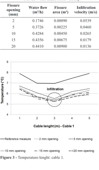
In each test, with a different opening in the membrane, indirect flow measurements were calculated. In order to calculate the infiltration velocity of the water in each fissure, water flow was divided by the fissure area. These values are presented in Table I.
It is possible to verify in Table I that the water flow increases with the size of the fissure opening.
In all tests average temperatures along the cables, during the initial stage (reference measurement) and in the final instant of heating were compared in order to verify the possible infiltration detection. The temperature values at the final heating instant and the reference period are presented in Figures 3, 4 and 5 for the first, second and third layer of the installed cables, respectively. It is important to point out that the reference temperatures were obtained before water flow.
It is possible to verify in Figures 3 to 5 that the cable temperatures measured without the presence of water (reference measure) were higher than the ones obtained with the presence of water, as expected, since the infiltrating water temperature was lower than the soil temperature.
All fissures were placed at the center of the 6 m long membrane and only 5 measuring points can be defined in each cable layer. It can be seen in Figures 3 to 5 that the lower temperatures values are at the center of the measuring range, which coincides with the openings placements and infiltration spots. The infiltration velocity increases with the opening size. However, diffusion and percolation of the water in soil also depend on soil settling/ compaction characteristics, among others. Thus, results did not show clear correlation between opening size and temperature magnitudes.
CONCLUSIONS
The concern about safety of constructions as well as the complex behavior of materials, such as concrete, has motivated the use monitoring systems for the detection of anomalies that could generate material or structural harm. A type of structure of
TABLE I
Water flow and infiltration velocity.
Fissure opening (mm)
Water flow
(m³/h)
Fissure area (m²)
Infiltration velocity (m/s)
2 0.1746 0.00090 0.0539
5 0.3726 0.00225 0.0460
10 0.4284 0.00450 0.0265
15 0.4356 0.00675 0.0179
20 0.4410 0.00900 0.0136
Figure 5 - Temperature-lenght: cable 3.
Figure 3 - Temperature-lenght: cable 1.
particular interest are the concrete face rockfill dams. During reservoir filling, displacements can lead to the appearance of fissures or cracks in the face slabs, resulting in water flow through the bulk. In that context, a series of tests were conducted in this work in order to verify and confirm the possibility of detecting infiltration with optical fiber cables through temperature measurements.
It was possible to verify its feasibility, considering three different distances for the cable from the infiltration spot. On the other hand, no clear correlation was detected between the opening (damage) size and the detected temperature values with the test arrangement.
Finally, it is evident that distributed optical fiber monitoring systems constitute an efficient infiltration detection device, especially for large structures.
ACKNOWLEDGMENTS
The authors greatfully acknowledge the support provided by Coordenação de Aperfeiçoamento de Pessoal de Nível Superior (CAPES), Universidade Federal do Paraná (UFPR), Universidade de Innsbruck (UIBK) and Institutos LACTEC – Instituto de Tecnologia para o Desenvolvimento for the development of this work.
REFERENCES
ASSIS WS. 2007. Computational systems to support the monitoring of civil engineering structures. Doctoral Thesis (in Portuguese) – Polytechnic School, University of São Paulo. São Paulo, Brazil, 265 p.
AUFLEGER M, CONRAD M, GOLTZ M, PERZLMAIER S AND PORRAS P. 2007. Innovative dam monitoring tolls based on distributed temperature measurement. Jordan J Civ Eng 1(1): 29-37.
AUFLEGER M, ETZER T, DORNSTÄDTER J AND MANGAROVSKI O. 2011. Leakage detection for rockfill dams with asphaltic core. In: International Symposium on Modern Technologies and Long-term Behavior of Dams. Zhengzhou, China, 7 p.
BAILEY D AND WRIGHT E. 2003. Practical fiber optics. Elsevier: Oxford, 260 p.
ETZER T, AUFLEGER M AND DORNSTÄDTER J. 2012. The use of distributed fiber optic measurements in hydraulic engineering. In: HydroVision Russia Conference & Exhibition. Moscou, Rússia, 6 p.
FAZAN JA. 2010. Application of global congruence test and geometric analysis to detect displacements in geodetic networks: case study at Itaipu HPP. Master´s Dissertation (in Portuguese) – Department of Transport Engineering – Polytechnic School, University of São Paulo. São Paulo, Brazil, 277 p. Available at: http://www.teses.usp.br/ teses/disponiveis/3/3138/tde-18112010-120841/publico/ Dissertacao_Jardel_Aparecido_Fazan.pdf. (Unpublished). GOLTZ M. 2011. Contribution to monitoring of embankment
dams by means of distributed fibre optic measurements. Doctoral Thesis (Doktor der Technischen Wissenschaften) – Fakultät für Bauingenieur Wissenschaften, Leopold– Franzens Universität Innsbruck, Austria, 202 p.
HOEPFFNER R. 2008. Distributed fiber optic strain sensing in hydraulic concrete and earth structures: measuring theory and field investigations on dam and landslides. Doctoral Thesis (Doktor - Lehrstuhl für Wasserbau und Wasserwirtschaft) – Technische Universität München, Germany, 212 p.
IMAI M AND FENG M. 2012. Sensing optical fiber installation study for crack identification using a stimulated Brillouin-based strain sensor. SHM 11(5): 501-509.
JOHANSSON S. 1997. Seepage monitoring in embankment dams. Doctoral Thesis – Department of Civil and Environmental Engineering, Division of Hydraulic Engineering, Royal Institute of Technology Stockholm, Sweden, 62 p.
JOHANSSON S AND SJÖDAHAL P. 2004. Downstream seepage detection using temperature measurements and visual inspection – monitoring experiences from Røsvatn field test dam and large embankment dams in Sweden. In: Proceedings Stability and Breaching of Embankment Dams, EBL. Oslo, Noruega, 20 p.
LACERDA LA AND SOARES MA. 2010. 5 years of temperature monitoring with distributed fiber optic sensors in the RCC dam of the Fundão HPP (in Portuguese). In: VII Symposium on Small Hydroelectric Power Plants. São Paulo, Brazil, 10 p.
LEW JS AND LOH CH. 2014. Structural health monitoring of an arch dam from static deformation. J Civil Struct Health Monit 4(4): 245-253.
LORIGGIO DD AND SENEM PR. 2003. Concrete slab design criteria in concrete face rockfill dams (in Portuguese). In: V Epusp Symposium on Concrete Structures. São Paulo, Brazil, 12 p.
RIBEIRO AMS. 2009. Application of optical fiber sensors to the observation of the behavior of geotechnical works. Master’s Dissertation (in Portuguese) - Department of Geotechnics, Faculty of Sciences and Technology of the New University of Lisbon. Monte da Caparica, Portugal, 133 p. Available at: https://run.unl.pt/bitstream/10362/1952/1/ Ribeiro_2009.pdf. (Unpublished).
ROCHA RPO. 2011. Geotechnical instrumentation with fiber optics: monitoring of wetting front and analysis of the variation of the degree of saturation in sandy soils. Master’s Dissertation (in Portuguese) - Post-Graduate Program in Civil Construction, Federal University of Paraná. Curitiba,
Brazil, 112 p. www.prppg.ufpr.br/ppgecc/wp-content/ uploads/2016/files/dissertacoes/d0151.pdf. (Unpublished). THOMSON DJ. 2013. The economic case for life extension
of structures using structural health monitoring based on the delayed cost of borrowing. J Civil Struct Health Monit 3: 335-340.