A
DVANCES IN GRAPHENE
-
BASED
MATERIALS AND THEIR COMPOSITES WITH
FOCUS ON BIOMEDICAL APPLICATIONS
Artur Daniel Moreira Pinto
This dissertation is submitted to the Faculty of Engineering, University of
Porto, for the degree of Doctor of Philosophy in Biomedical Engineering.
Supervisors:
Prof. Dr. Fernão Domingos de Montenegro Baptista Malheiro de Magalhães Prof.ª Dr.ª Inês de Castro Gonçalves de Almada Lobo
Advances in GBMs and their composites with focus on biomedical applications
ACKNOWLEDGEMENTS
First, I would like to thank the unmatchable availability, all the support, advising, and resources made available from my supervisor, Prof. Fernão Magalhães, which were indispensable for the development of the work here presented.
I would like to thank my co-superviser, Prof. Inês Gonçalves, for making possible the beginning, and advising me through the development, of almost all the biological characterization component of this work at INEB-i3S, and university of Washington.
I would like to express my gratitude to everyone from ARCP, INEB-i3S, ISCS-N, and FEUP that cooperated with me during this period, as for example Carla Mora, Carolina Gonçalves, Diana Paiva, Daniela Sousa, Domingos Castro, Eva Ribeiro, Patrícia Henriques, Pedro Bandeira, Pedro Fonte, Rita Ferreira, Rui Cruz, Sarah Pontes, Susana Moreira, and Viviana Pinto. My acknowledgements to professors Adélio Mendes, Agostinho Moreira, Bruno Sarmento, Cristina Martins, Rui Guedes, and respective teams, for making available, and assistance while using their labs/equipment.
A mention of gratitude must be addressed to Prof. Buddy Ratner, and his team, for welcoming me and making all the conditions available for the development of my work during the visiting period at the Bioengineering Department of the University of Washington. My acknowledgments to Prof. James Bryers and his team, for the use of the equipment in their lab.
Finally, I thank my family for all the support they have been giving me since ever, without which it would not be possible for me to reach any goal, including the completion of this thesis.
Advances in GBMs and their composites with focus on biomedical applications
FUNDING ACKNOWLEDGEMENTS
Artur Pinto wishes to thank Fundação para a Ciência e a Tecnologia (FCT) for PhD grant SFRH/BD/86974/2012, funded by European Social Fund and Portuguese Ministry of Education and Science (MEC) through Programa Operacional Capital Humano (POCH).
This work was financially supported by: POCI-01-0145-FEDER-006939 (Laboratory for Process Engineering, Environment, Biotechnology and Energy – UID/EQU/00511/2013) and Project POCI-01-0145-FEDER-007274 (Institute for Research and Innovation in Health Sciences) funded by the European Regional Development Fund (ERDF), through COMPETE2020 - Programa Operacional Competitividade e Internacionalização (POCI) and by national funds, through FCT - Fundaç ão para a Ciência e a Tecnologia.
Funding for this work was partially provided by FEDER, through Programa Operacional Factores de Competitividade – COMPETE, and by National Funding through FCT – Fundação para a Ciência e a Tecnologia, in the framework of project PTDC/EME-PME/114808/2009 and project PTDC/CTM-BIO/4033/2014.
Experiments at the University of Washington were funded, in part, through the University of Washington Engineered Biomaterials (UWEB21) Engineering Research Center.
Advances in GBMs and their composites with focus on biomedical applications
LIST OF PUBLICATIONS
1. A.M. Pinto, S. Moreira, I.C. Goncalves, F.M. Gama, A.M. Mendes, F.D. Magalhaes, Biocompatibility of poly(lactic acid) with incorporated graphene-based materials, Colloids and Surfaces B: Biointerfaces 104 (2013) 229-238.
2. A.M. Pinto, I.C. Gonçalves, F.D. Magalhães, Graphene-based materials biocompatibility: a review, Colloids and Surfaces B: Biointerfaces 111 (2013) 188-202.
3. A.M. Pinto, C. Gonçalves, D.M. Sousa, A.R. Ferreira, J.A. Moreira, I.C. Gonçalves, F.D. Magalhães, Smaller particle size and higher oxidation improves biocompatibility of graphene-based materials, Carbon 99 (2016) 318-329.
4. C. Gonçalves*, A.M. Pinto*, A.V. Machado, J.A. Moreira, I.C. Gonçalves, F.D. Magalhães, Biocompatible reinforcement of poly(lactic acid) with graphene nanoplatelets, Polymer Composites (2016) article in press, DOI: 10.1002/pc.24050. *equal contribution
5. A.M. Pinto, J.A. Moreira, F.D. Magalhães, IC Gonçalves, Polymer surface adsorption as a strategy to improve the biocompatibility of graphene nanoplatelets, Colloids and Surfaces B: Biointerfaces 146 (2016) 818-824.
6. A.M. Pinto, C. Gonçalves, I.C. Gonçalves, F.D. Magalhães, Effect of biodegradation on thermo-mechanical properties and biocompatibility of poly (lactic acid)/graphene nanoplatelets composites, European Polymer Journal 85 (2016) 431-444.
Advances in GBMs and their composites with focus on biomedical applications
ABSTRACT
Graphene is the elementary structure of graphite, being a one carbon atom thick sheet, composed of sp2 carbon atoms arranged in a flat honeycomb structure. Due to its unique characteristics,
graphene has unmatched electronic, mechanical, optical, and thermal properties, amongst others. In 2010, Geim and Novoselov were awarded the Nobel prize "for groundbreaking experiments regarding the two-dimensional material graphene". Since then significant financial and human investment has been made on graphene applications in the most diverse forms. This means that graphene tends to become widespread. However, only a small fraction of the research focuses on the biological field.
Poly(lactic acid) (PLA) is an aliphatic polyester derived from renewable sources, which has several applications in various areas. In bioengineering, PLA is used for production of bioresorbable artificial ligaments, hernia repair meshes, scaffolds, screws, surgical plates, and suture yarns. To make this material more effective in several applications some properties can be improved, being mechanical performance usually the most relevant. Reinforcement with small amounts of nanofillers, as graphene/based materials (GBMs) is an interesting option because it allows improvement of target properties without changing PLA’s main characteristics.
Since GBMs have several potential applications in biomedical engineering and biotechnology, this thesis is focused in understanding their biointeractions, and which sort of physical-chemical features have impact on their biocompatibility. It also studies GBMs as fillers for PLA, and the way by which they improve PLA properties and affect biocompatibility.
An extensive literature review is presented on the key issues regarding GBMs biocompatibility, namely production methods, physical-chemical properties, concentrations, time of exposure, and encapsulation in polymer matrices. In this thesis, the biological properties of GBMs dispersed in liquid media are studied in in vitro assays, as well as how they are affected by the materials’ morphology, degree of oxidation, and surface modification with polymers. Human fibroblasts are used as an in vitro model to characterize GBMs biocompatibility, in terms of induction of reactive oxygen species production, metabolic activity changes, effect on cell morphology, evaluation of membrane damages, and particles internalization. Smaller graphene nanoplatelets (GNP) are observed to be generally more biocompatible than larger sized ones, which tend to cause membrane damages. Also, complete oxidation of GNP folds its sharp edges, therefore preventing toxicity. Surface adsorption of poly(vinyl alcohol) increases GNP size, preventing its internalization, therefore improving its biocompatibility. These results are relevant for the materials’ use in biomedical applications.
Advances in GBMs and their composites with focus on biomedical applications
Literature on composites of PLA with carbon-based nanomaterials is also reviewed in depth. Usually, GBMs are reported to improve several PLA properties, namely thermal, electrical, mechanical, and biological properties. However, GBMs physico-chemical properties, composites production methods, and ideal incorporation amounts vary between studies.
In this thesis, the production of PLA/GNP composites is explored by two different methods: solvent mixing followed by doctor blading, and melt-blending followed by compression moulding. Optimization of both methods is performed, in order to improve PLA physical-chemical properties. GNP improves the mechanical properties of PLA, and reduces the decay of its mechanical performance after 6 months degradation in physiological conditions. In addition, the composites have stable behaviour under cyclic creep-relaxation testing, while PLA exhibits significant cumulative permanent strain, and ruptures after a few cycles. This is particularly relevant in the context of PLA uses in orthopedics, or other implantable materials that need to have a suitable mechanical performance along time when inside the body.
Improvements in biological properties are also observed, namely increase in cell proliferation for PLA/graphene oxide composites, and decrease of platelets activation for PLA/graphene nanoplatelets composites, both produced by solvent mixing. Composites produced by melt-blending, and their degradations products, do not affect cell metabolic activity and morphology. Finally, the above-mentioned results are discussed in the light of the most recently available literature reports, and new research perspectives are pointed out. In vivo characterization of the PLA/GNP composites is being performed, since they present outstanding mechanical performance after degradation in biological conditions, and lack of in vitro toxicity, which perspectives them as a promising material for biomedical applications.
Keywords
graphene; poly(lactic acid); biocompatibility; biomaterials; biodegradation; composites; mechanical properties.
Advances in GBMs and their composites with focus on biomedical applications
RESUMO
O grafeno é a estrutura elementar da grafite, sendo uma folha com a espessura de um átomo de carbono, composta por átomos de carbono com hibridização sp2, ordenados numa estrutura de
colmeia 2D. Devido a estas características únicas, o grafeno possui ímpares propriedades eletrónicas, mecânicas, óticas, térmicas, entre outras. Em 2010, o prémio Nobel da Física foi atribuído a Geim e Novoselov “por experiências revolucionárias com o material bidimensional grafeno”. Desde então, tem sido feito um significativo investimento financeiro e humano nas aplicações do grafeno nas mais diversas formas. Isto significa que o grafeno tende a estar disseminado, no entanto, apenas uma pequena parte da investigação na área está focada no campo biológico.
O ácido poliláctico (PLA) é um poliéster alifático derivado de fontes renováveis, que tem aplicações em diversas áreas. Em bioengenharia, o PLA é usado para produção de ligamentos artificiais bioabsorvíveis, redes para reparação de hérnias, estruturas para regeneração de tecidos, parafusos e placas cirúrgicas e fios de sutura. Para tornar este material mais eficaz para várias aplicações, algumas propriedades podem ser melhoradas, sendo o desempenho mecânico normalmente a mais relevante. O reforço com pequenas quantidades de nano-cargas, como os materiais com base em grafeno (GBMs) é uma opção interessante, pois permite a melhoria das propriedades alvo sem modificar as principais características do PLA.
Como os GBMs têm várias potenciais aplicações em engenharia biomédica e biotecnologia, esta tese está focada na compreensão das suas bio-interações e no tipo de características físico-químicas que têm impacto na sua biocompatibilidade. Também estuda os GBMs como cargas para incorporação em PLA e a forma como melhoram as propriedades do PLA e afetam a sua biocompatibilidade.
É apresentada uma extensa revisão bibliográfica dos pontos-chaves da biocompatibilidade dos GBMs, nomeadamente métodos de produção, propriedades físico-químicas, concentrações, tempos de exposição e encapsulação em matrizes poliméricas. Nesta tese, as propriedades biológicas dos GBMs quando dispersos em meio líquido, são estudadas em ensaios in vitro, assim como a forma como estas são afetadas pela morfologia dos materiais, grau de oxidação e modificação superficial com polímeros. Fibroblastos humanos são usados como modelo in vitro para caracterizar a biocompatibilidade dos GBMs, em termos de indução de espécies reativas de oxigénio, alterações na atividade metabólica, efeito na morfologia celular, avaliação de danos na membrana e internalização de partículas. Foi observado que nanoplaquetas de grafeno (GNP) mais pequenas, no geral são mais biocompatíveis que as de tamanho maior, que tendem a causar danos nas membranas celulares. Para além disso, a oxidação completa das GNP dobra as suas
Advances in GBMs and their composites with focus on biomedical applications
extremidades afiadas, prevenindo assim a sua toxicidade. A adsorção superficial de álcool polivinílico aumenta o tamanho das GNP, impedindo a sua internalização e assim melhorando a sua biocompatibilidade. Estes resultados são relevantes tendo em conta as aplicações biomédicas destes materiais.
A literatura sobre materiais compósitos de PLA com nanomateriais com base em carbono também é revista em profundidade. É descrito que normalmente os GBMs melhoram várias propriedades do PLA, nomeadamente térmicas, elétricas, mecânicas e biológicas. No entanto, as propriedades físico-químicas dos GBMs, os métodos de produção dos compósitos e quantidades de GBMs incorporadas variam entre os estudos.
Nesta tese, a produção de compósitos de PLA/GBMs é explorada usando dois métodos diferentes: 1) mistura em solvente, seguida de doctor blading; 2) mistura em fundido, seguida de moldagem por compressão. É realizada otimização de ambos os métodos, de forma a melhorar as propriedades físico-químicas do PLA. As GNP melhoram as propriedades mecânicas do PLA e reduzem o decaimento do seu desempenho mecânico após degradação em condições fisiológicas durante 6 meses. Para além disso, os compósitos apresentam comportamento estável sob testes cíclicos de fluência-relaxamento, enquanto que o PLA apresenta deformação cumulativa constante e rompe após poucos ciclos. Isto é particularmente relevante tendo em conta as aplicações do PLA em ortopedia ou noutros materiais implantáveis que necessitem de ter um desempenho mecânico adequado ao longo do tempo quando no interior do corpo.
São observadas melhorias nas propriedades biológicas, nomeadamente aumento da proliferação celular à superfície de filmes compósitos de PLA/óxido de grafeno e decréscimo da ativação de plaquetas para PLA/nanoplaquetas de grafeno, ambos produzidos por mistura em solvente. É observado que os compósitos produzidos por mistura em fundido e os seus produtos de degradação não afetam a atividade metabólica nem a morfologia celular.
Finalmente, os resultados acima mencionados são discutidos à luz da literatura mais recente e novas perspetivas de investigação apontadas. Está a ser realizada caracterização in vivo dos compósitos de PLA/GNP, uma vez que apresentam um desempenho mecânico notável após degradação em condições biológicas e não são tóxicos in vitro, o que os torna um material promissor para aplicações biomédicas.
Palavras-chave
grafeno; ácido polilático; biocompatibilidade; biomateriais; biodegradação; compósitos; propriedades mecânicas.
Advances in GBMs and their composites with focus on biomedical applications
TABLE OF CONTENTS
1 INTRODUCTION
1
1.1 Scope 3
1.2 Key concepts 3
1.2.1 Biomaterials and biocompatibility 3 1.2.2 Graphene-based materials (GBMs) 6
1.2.3 Poly(lactic acid) (PLA) 9
1.3 Motivation and Scope 11
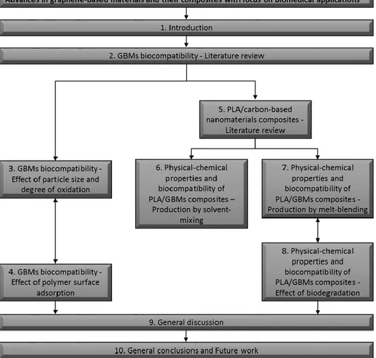
1.4 Dissertation Outline 12
2 GBMs BIOCOMPATIBILITY – LITERATURE REVIEW
19
2.1 Scope 21
2.2 State of the art 21
2.2.1 Introduction 21
2.2.2 In vitro biocompatibility studies 25 2.2.3 In vivo biocompatibility studies 28
2.2.4 Hemocompatibility 35
2.2.5 Biocompatibility of composite materials containing GBMs 35
2.3 Conclusions 42
3 GBMs BIOCOMPATIBILITY – EFFECT OF PARTICLE SIZE AND
DEGREE OF OXIDATION
51
3.1 Scope 53
3.2 State of the art 53
3.3 Materials and methods 55
3.3.1 Graphene-based materials oxidation 55 3.3.2 GBMs physical-chemical characterization 55 3.3.3 GBMs biocompatibility 57 3.3.4 Statistical analysis 61 3.4 Results 61 3.4.1 GBMs physical-chemical characterization 61 3.4.2 GBMs biocompatibility 67 3.5 Discussion 74 3.6 Conclusions 77
4 GBMs BIOCOMPATIBILITY – EFFECT OF POLYMER SURFACE
ADSORPTION
83
4.1 Scope 85
4.2 State of the art 85
4.3 Materials and methods 87
4.3.1 Materials preparation 87 4.3.2 Physical-chemical characterization 87 4.3.3 Biocompatibility evaluation 88 4.3.4 Statistical analysis 90 4.4 Results 90 4.4.1 Physical-chemical characterization 90 4.4.2 Biocompatibility evaluation 92
Advances in GBMs and their composites with focus on biomedical applications
4.5 Discussion 97
4.6 Conclusions 99
5 PLA/CARBON-BASED NANOMATERIALS COMPOSITES (CBNs) –
LITERATURE REVIEW
103
5.1 Scope 105
5.2 State of the art 105
5.2.1 Introduction 105
5.2.2 Materials 106
5.2.3 Production of PLA/CBNs composites 112 5.2.4 Properties of PLA/CBNs Composites 114
5.3 Conclusions 135
6 PHYSICAL-CHEMICAL PROPERTIES AND BIOCOMPATIBILITY
OF PLA/GBMs COMPOSITES - PRODUCTION BY SOLVENT-MIXING
147
6.1 Scope 149
6.2 State of the art 149
6.3 Materials and methods 151
6.3.1 Materials 151
6.3.2 Preparation of GO 152
6.3.3 Preparation of PLA/GO films 152
6.3.4 Preparation of PLA/GNP films 152
6.3.5 Films surface characterization 152 6.3.6 In vitro biocompatibility assays 153
6.3.7 Statistical analysis 156
6.4 Results and discussion 156
6.4.1 Topographical characterization 156
6.4.2 Chemical characterization 158
6.4.3 Wettability of the films surface 161 6.4.4 In vitro biocompatibility assessment 163 6.4.5 Platelet adhesion and activation 165
6.5 Conclusions 169
7 PHYSICAL-CHEMICAL PROPERTIES AND BIOCOMPATIBILITY
OF PLA/GBMs COMPOSITES - PRODUCTION BY MELT-BLENDING
173
7.1 Scope 175
7.2 State of the art 175
7.3 Materials and methods 178
7.3.1 Materials 178
7.3.2 Preparation of PLA/GNP composites 178 7.3.3 X-ray photoelectron spectroscopy (XPS) 178 7.3.4 Fourier transform Infrared Spectroscopy (FTIR) 179
7.3.5 Tensile properties 179
7.3.6 Thermal analysis 179
7.3.7 Scanning Electron Microscopy (SEM) 180
7.3.8 Raman spectroscopy 180
Advances in GBMs and their composites with focus on biomedical applications
7.4 Results and discussion 181
7.4.1 GNP-C physico-chemical characterization 181
7.4.2 FTIR analysis 182
7.4.3 Mechanical characterization 183
7.4.4 Thermal analysis 185
7.4.5 Scanning electron microscopy 189
7.4.6 Raman spectroscopy 191
7.4.7 Biocompatibility with fibroblasts 194
7.5 Conclusions 196
8 PHYSICAL-CHEMICAL PROPERTIES AND BIOCOMPATIBILITY
OF PLA/GBMs COMPOSITES - EFFECT OF BIODEGRADATION 201
8.1 Scope 203
8.2 State of the art 204
8.3 Materials and methods 205
8.3.1 Materials 205
8.3.2 Preparation and degradation of PLA and PLA/GNP composites 206 8.3.3 Physico-chemical characterization 206 8.3.4 Mechanical properties characterization 207
8.3.5 Biocompatibility evaluation 208
8.3.6 Statistical analysis 209
8.4 Results 210
8.4.1 Physical-chemical characterization 210
8.4.2 Mechanical characterization 212
8.4.3 Biocompatibility with human fibroblasts 216
8.5 Discussion 220
8.6 Conclusions 223
9 GENERAL DISCUSSION
229
10 CONCLUSIONS AND FUTURE WORK
239
10.1 General conclusions 241
10.2 Ongoing and Future work 242
11 APPENDICES
245
APPENDIX A
Supplementary material for Chapter 3GBMs biocompatibility - effect of particle size and degree of oxidation 247
APPENDIX B
Supplementary material for Chapter 4GBMs biocompatibility - effect of polymer surface adsorption 257
APPENDIX C
Supplementary material for Chapter 8Physical-chemical properties and biocompatibility of PLA/GBMs composites -
Advances in GBMs and their composites with focus on biomedical applications
LIST OF TABLES
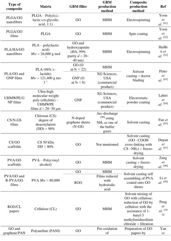
Table 2.1: GBMs and respective production methods. ... 23
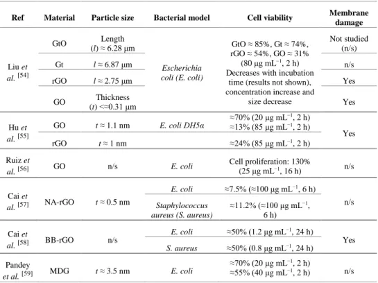
Table 2.2: Effect of GBMs on bacteria viability and membrane integrity... 26
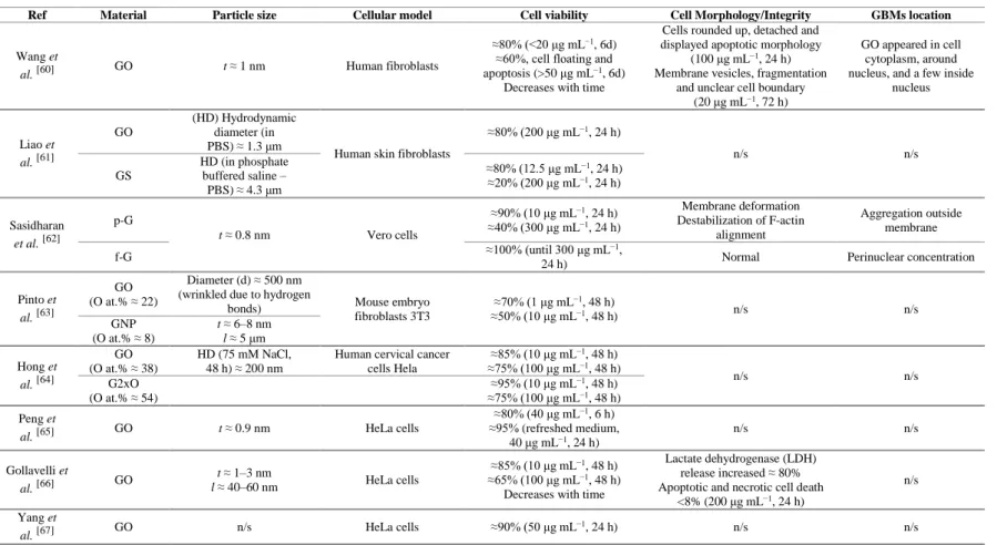
Table 2.3: Effect of GBMs on mammalian cell structure, metabolism and viability... 29
Table 2.4: GBMs in vivo biocompatibility... 32
Table 2.5: GBMs hemocompatibility. ... 36
Table 2.6: Types of GBMs composites used in biocompatibility studies and respective production methods. ... 37
Table 2.7: Biocompatibility of GBMs composites. ... 39
Table 5.1: Mechanical properties of PLA/CBNs composites in comparison with non-modified PLA. Production methods and CBNs characteristics. ... 117
Table 5.2: Electrical properties of PLA/CBNs composites in comparison with non-modified PLA. Production methods and CBNs characteristics. ... 123
Table 5.3: Thermal properties of PLA/CBNs composites in comparison with non-modified PLA. Production methods and CBNs characteristics. ... 129
Table 5.4: Biological properties of PLA/CBNs composites in comparison with non-modified PLA. Production methods and CBNs characteristics. ... 133
Table 6.1: Roughness parameters for PLA, PLA/GO and PLA/GNP films. Sa – arithmetic average height of the surface, Sp – maximum peak height, Sv – maximum valley depth, Sz – maximum height of the surface. Results are presented as mean and standard deviation (in parenthesis) for n = 3. ... 158
Table 6.2: Atomic composition of graphite, GNP and GO, determined by XPS. Results are presented as mean and standard deviation (in parenthesis). ... 160
Table 6.3: Atomic composition analysis by XPS of the surface of PLA, PLA/GO and PLA/GNP films. Results are presented as mean and standard deviation (in parenthesis) for n = 3. ... 161
Table 6.4: Contact angles at 60 s of H2O, ethane-1,2-diol and hexadecane on PLA, PLA/GO and PLA/GNP films. Results are presented as mean and standard deviation (in parenthesis) for n = 3. ... 161
Table 7.1: Glass transition temperature (Tg) and melting temperature (Tm) for PLA and PLA/GNP-C composites (180°C, 20 min, and 50 rpm) with different filler contents. ... 187
Advances in GBMs and their composites with focus on biomedical applications
LIST OF FIGURES
Figure 1.1: Evolution of the number of publications mentioning biomaterials and biocompatibility from 1970 to 2016. Source: Scopus; keywords searched: “biomaterial” - “biocompatibility”; search date: 30/12/2016. ... 6 Figure 1.2: Timeline of selected events in the history of the preparation, isolation, and
characterization of graphene. Reprinted from reference 29, with permission from Wiley, Copyright (2016). ... 8 Figure 1.3: Evolution of the number of publications mentioning graphene and graphene +
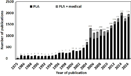
biocompatibility from 2004 to 2016. Source: Scopus; keywords searched: “graphene” - “graphene; biocompatibility”; search date: 31/12/2016. The number of “graphene; biocompatibility” publications was subtracted from “graphene” ones in the graph. Labels on top of the bars show the number of “graphene + biocompatibility” publications. ... 9 Figure 1.4: Evolution of the number of publications mentioning PLA and PLA + medical from 1975 to 2016. Source: Scopus; keywords searched: “PLA” - “PLA; medical”; search date: 31/12/2016. The number of “PLA; medical” publications was subtracted from “PLA” ones in the graph. Labels on top of the bars show the number of “PLA + medical” publications. ... 11 Figure 1.5: Schematic diagram illustrating the different topics covered in this thesis and their
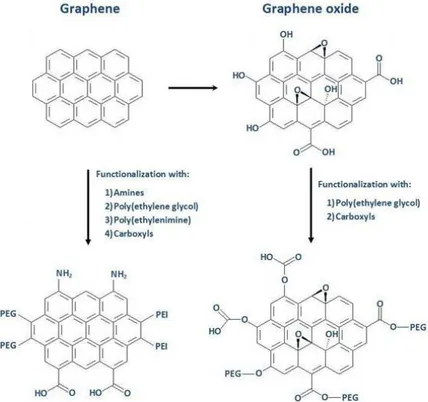
articulation. ... 13 Figure 2.1: Simplified scheme showing graphene and graphene oxide structures and some
examples of functionalization for both materials. ... 22 Figure 3.1: SEM images of dry powders of GNP-C at (A) 500×, (B) 100000×; GNP-M at (C)
500×, (E) 4000×, (F) 20000×, and (D) 100000×; GNP-M-ox-1:3 at (G) 4000×, and (H) 20000×; and of GNP-M-ox-1:6 at (I) 4000×, and (J) 20000×. Scale bars are 1 (B, D), 5 (F, H, J), 30 (E, G, I), and 200 µm (A, C). ... 62 Figure 3.2: Particle size distributions of GNP-C, GNP-M and GNP-M-ox-1:3 and 1:6 dispersed in
water at a concentration of 100 μg mL−1. ... 63 Figure 3.3: A) Table shows atomic composition of GBMs and content of C 1s chemical groups
resulting from spectra fitting (*fitting for oxygen groups of GNP-C and M could not be performed due to having low content); B) XPS spectra for the core level C 1s for GNP-C, M, GNP-M-ox-1:3 and 1:6; C, D, E) spectra fitting for GNP-M, GNP-M-ox-1:3 and 1:6, respectively. Deconvoluted peaks shown correspond to: 1) C=C (sp2), 2) C-C (sp3), 3)
C-OH, 4) C-O-C, 5) C=O, and 6) O-C=O. ... 64 Figure 3.4: Representative unpolarized Raman spectra for GNP-C, GNP-M, GNP-M-ox-1:3, and
GNP-M-ox-1:6 powders, acquired at ambient conditions. B) Intensity ratio of the (D/G) bands of GBMs powders. Results are presented as mean and standard deviation (n = 3). C) TGA curves and weight loss for GBMs powders. ... 66 Figure 3.5: Percentage of RBCs lysis after 3 h incubation at 37 °C with PBS (negative control),
and different concentrations of GBMs (100, 200 and 500 μg mL−1). Positive control (Triton 1% in PBS) resulted in 100% hemolysis. Results are presented as mean and standard deviation (n = 3). Greek symbols represent statistically significant differences between samples within the same concentrations (p < 0.05). No significant differences were observed between PBS and GBMs for all concentrations tested (p > 0.05). ... 67 Figure 3.6: A) HFF-1 cells viability after incubation with GBMs in DMEM+, at 24, 48 and 72 h.
Cell metabolic activity is represented as percentage in comparison with cells cultured in DMEM+ (100%). Results are presented as mean and standard deviation (n = 6). The red line at 70%, marks the toxicity limit, according to ISO 10993-5:2009(E). Statistical analysis is presented in Table A1. B) Percentage of HFF-1 cell death after 72 h of incubation with GBMs. Cell death percentage was corrected by subtraction of the value for cells cultured in DMEM+ (negative control for cell death). Results are presented as mean and standard deviation (n = 3). Statistically significant differences, analysed within each concentration between all GBMs are represented by c – GNP-C, m – GNP-M, 1:3 – GNP-M-ox-1:3 (differences were only found comparing with GNP-M-ox-1:6); Differences comparing with DMEM+ are represented by Ø. Symbols not underlined represent p < 0.05, for p < 0.01 signs are underlined. ... 69
Advances in GBMs and their composites with focus on biomedical applications
Figure 3.7: Intracellular reactive oxygen species levels (ROS) induced by C, M, GNP-M-ox-1:3, and GNP-M-ox-1:6 (1, 10, 50 μg mL−1), when incubated with HFF-1 cells for 1 h. Negative control for ROS levels increase is PBS (considered 100%) and positive control H2O2 100 mM. Results are presented as mean and standard deviation (n = 3). Statistically significant differences, analysed within each concentration are represented by c – GNP-C, m – GNP-M, 1:3 – GNP-M-ox-1:3, 1:6 – GNP-M-ox-1:6. Symbols represented above a sample concentration indicate that sample is different from samples represented by the symbols for that concentration. Symbols are not underlined when p < 0.05 and underlined when p < 0.01. Above 10 μg mL−1 all samples are different from PBS (p < 0.01). ... 71 Figure 3.8: Representative immunofluorescence images of HFF-1 cells after 72 h incubation with
50 μg mL−1 of GNP-C, GNP-M, GNP-M-ox-1:3 and GNP-M-ox-1:6. Triton 0.1% in
DMEM+ was used as positive control for changed morphology and cells grown in DMEM+ as negative control. Cells were stained with DAPI (nuclei) – blue and Phalloidin (F-actin in cytoskeleton) – green. Scale bar represents 200 μm. ... 73 Figure 3.9: TEM images of HFF-1 cells incubated for 72 h with 100 μg mL−1 GBMs. A, B –
DMEM+, C – GNP-C (a – particle interacting with plasma membrane (pm), b – particle internalized and in contact with plasma membrane, c – particle inside a vesicle (vs) in cytoplasm), D – GNP-C particles spread in cytoplasm and interaction with a mitochondria (mt), E − Membrane rupture (white arrow) and cytoplasmic content leakage caused by GNP-M particle, F – GNP-M in cytoplasm (nc – nucleus), G – GNP-M-ox-1:3 (a – interacting with plasma membrane, b – entering through plasma membrane, c – vesicle containing an internalized particle), H – GNP-M-ox-1:6 particle in contact with plasma membrane causing no damages, I – GNP-M-ox-1:6 inside cytoplasm. Scale bar represents 0.5 μm for all images except for image A, in which it represents 2 μm... 73 Figure 4.1: A) Particle size distributions of GBMs dispersed in water at a concentration of 100 μg
mL−1. B) Particle size distributions for a narrower size range than in image A, to allow comparison between GBMs with smaller size distribution. ... 91 Figure 4.2: Percentage of RBCs lysis after 3 h incubation at 37 °C with PBS (negative control)
and different concentrations of GBMs (100, 200 and 500 μg mL−1). The positive control (Triton 1% in PBS) resulted in 100% hemolysis (data not shown). The results are presented as the mean and standard deviation (n = 3). Greek symbols represent statistically significant differences between samples within the same concentration (p < 0.05). ... 92 Figure 4.3: A) HFF-1 cell viability after incubation with GBMs in DMEM+, at 24, 48 and 72 h.
Cell mitochondrial metabolic activity is represented as a percentage in comparison with cells cultured in DMEM+ (100%). The results are presented as the mean and standard deviation (n = 6). The red line at 70% marks the toxicity limit according to ISO 10993-5:2009(E). The statistical analysis is presented in Table S1. B) Percentage of HFF-1 cell death after 72 h of incubation with GBMs. Cell death percentage was corrected by subtraction of the value for cells cultured in DMEM+ (negative control for cell death). The results are presented as the mean and standard deviation (n = 3). Statistically significant differences (p < 0.05) analysed within each concentration between all GBMs are represented by Greek symbols. C) Intracellular reactive oxygen species levels (ROS) induced by GBMs (1, 10, 50 μg mL−1) when incubated with HFF-1 cells for 1 h. The negative control for ROS production is PBS (considered 100%) and the positive control is H2O2 100 mM. The results are presented as the mean and standard deviation (n = 3). No
statistically significant differences (p > 0.05) were observed between samples within each concentration. ... 94 Figure 4.4: TEM images of HFF-1 cells incubated for 72 h with 100 μg mL−1 GBMs. DMEM+ −
A [33], B (cyt − cytoplasm, nc − nucleus); GNP-C − C (a − particle interacting with pm − plasma membrane, b − particles inside cytoplasm, c − particle in contact with nucleus), D (particles inside cytoplasm, vs- vesicles); GNP-C-PVA − E (agglomerated particles inside cytoplasm), F (particle outside plasma membrane); GNP-C-HEC − G (particles spread in cytoplasm), H (particles interacting with mitochondria − mt). Scale bar represents 0.5 μm, except for A − 2 μm... 96 Figure 5.1: Evolution Scheme showing the relation between different types of GBMs and their
Advances in GBMs and their composites with focus on biomedical applications
Figure 5.2: Scheme showing the different types of modifications performed on CBNs prior to incorporation in PLA. ... 110 Figure 5.3: Scheme showing the different production methods of PLA/CBNs composites. ... 111 Figure 6.1: Activation degree of platelets at the surface of the films. Representative images of
non-activated (A and B) and activated (C and D) platelets, at 20,000× magnification. ... 155 Figure 6.2: Representative 3D images of the topography of the surface of pristine PLA (A),
PLA/GO (B) and PLA/GNP (C) films. ... 157 Figure 6.3: Reflected light microscopy of the surface of PLA (A), PLA/GO (B) and PLA/GNP
(C) films. ... 159 Figure 6.4: XPS spectra for the core level C 1s (after fitting) of graphite, GO and GNP powders. ... 160 Figure 6.5: Contact angle images for: A – water on PLA, B – ethane-1,2-diol on PLA, C –
hexadecane on PLA, D – hexadecane on PLA/GO and E – hexadecane on PLA/GNP film surface. ... 162 Figure 6.6: Dispersive and polar components of the total surface free energy of PLA, PLA/GO
and PLA/GNP films. ... 163 Figure 6.7: Cell proliferation inhibition index for mouse embryo fibroblasts, cultured on PLA,
PLA/GO and PLA/GNP films. Results are presented as mean and error bars represent SD. *Significantly different (p < 0.05). ... 164 Figure 6.8: Fluorescence microscopy of mouse embryo fibroblasts after 48 h incubation in the
direct contact assay: A – Agar (negative control); B – positive control (latex rubber); C and D – PLA; E – PLA/GO and F – PLA/GNP. ... 165 Figure 6.9: Platelet adhesion on PLA, PLA/GO and PLA/GNP films surface, pre-immersed in
PBS or plasma. Degree of activation of the platelets adhered to the surface of the films pre-immersed in PBS or in plasma. A – activated, NA – non activated. Results are presented as mean and error bars represent standard deviation. *Significantly different (p < 0.05). ... 167 Figure 6.10: Platelets adherent on the surface of PLA (A), PLA/GO and (B) PLA/GNP films pre-immersed in plasma (images of the films pre-pre-immersed in PBS are not shown). ... 168 Figure 7.1: (a) XPS spectrum for atomic composition of GNP-C powder; (b) TGA curve for
GNP-C powder. ... 182 Figure 7.2: FTIR spectra for PLA and PLA/GNP-C 0.25 wt.% (180°C, 20 min, and 50 rpm). .. 183 Figure 7.3: Effect of increasing nanofiller content on mechanical properties of PLA/GNP-C
composites under the same processing conditions (180°C, 20 min, and 50 rpm): (a) Young's modulus; (b) tensile strength; (c) toughness. Error bars represent standard deviations computed from measurements on at least 10 samples. ... 184 Figure 7.4: Effect of mixing time and rotation speed on mechanical properties of PLA/GNP-C
composites processed at 180°C, for a filler content of 0.25 wt.%: (a) Young's modulus; (b) tensile strength; (c) toughness. Error bars represent standard deviations computed from measurements on at least 10 samples. ... 186 Figure 7.5: DSC thermograms for PLA and PLA/GNP-C (180°C, 20 min, and 50 rpm) composites
with different filler contents. ... 187 Figure 7.6: (a) TGA; (b) −dTG curves for PLA and PLA/GNP-C composites with different filler
contents (180°C, 20 min, and 50 rpm). ... 188 Figure 7.7: (a) SEM images of GNP-C powder at 100,000× magnification; (b) fracture surfaces
(under liquid nitrogen) of PLA/GNP-C composites (180°C, 20 min, and 50 rpm), showing GNP-C agglomerates at 40,000× magnification; (c, d) individualized platelets at 200,000× magnification, for loadings of 0.25 and 0.5 wt.% in PLA (180°C, 20 min, and 50 rpm), respectively... 189 Figure 7.8: (a) Cumulative plots of number of agglomerates per unit of area (mm2) as a function
of agglomerate length, for different GNP-C loadings (180°C, 20 min, and 50 rpm); (b) SEM images of fracture of surfaces for 5,000× magnification. ... 190 Figure 7.9: Representative unpolarized Raman spectra for PLA, GNP-C powder, and PLA/GNP-C 0.5 wt.% 20 min, recorded at ambient conditions. ... 191 Figure 7.10: Example of Raman spectrum fitting according to Eq. (1) to PLA/GNP-C 0.5 wt.% 20
min. Bands 1–3 are attributed to D band and 5–6 to G band of GNP-C, while band 4 arises from PLA matrix. ... 192
Advances in GBMs and their composites with focus on biomedical applications
Figure 7.11: Unpolarized Raman spectra of PLA and PLA/GNP-C 0.1, 0.25, and 0.5 wt.% for (a) 10 and (b) 20 min mixing times. ... 193 Figure 7.12: Intensity ratios of the D and G bands of monolayer C (peak 2/peak 6) for GNP-C powder and PLA/GNP-GNP-C 0.1, 0.2, and 0.5 wt.% for 10 and 20 min mixing times. Results are presented as average values and error bars represent standard deviation (n > 3). ... 194 Figure 7.13: Metabolic activity of HFF-1 cells cultured at the surface of PLA/GNP-C 0.25 wt.%
(180 °C, 20 min, and 50 rpm) in DMEM+, at 24, 48, and 72 h. Cell metabolic activity is represented as percentage in comparison with cells cultured at PLA surface in DMEM+ (100%). Results are presented as mean and standard deviation (n = 6). The red line at 70% marks the toxicity limit, according to ISO 10993-5:2009(E). For positive control of cell death, cells were cultured at PLA surface in DMEM+/Triton 0.1%, with metabolic activity being close to 0% (data not shown). For representative immunofluorescence images of HFF-1 at 72 h, cells were stained with DAPI (nuclei) blue and phalloidin (F-actin in cytoskeleton) green. Bottom line presents the phase-contrast images of materials surface. Scale bar represents 100 μm. ... 195 Figure 8.1: SEM images of PLA 0 M (A), PLA 6 M (B), PLA/GNP-M 0.25 wt.% 0 M (C),
PLA/GNP-M 0.25 wt.% 6 M (D), PLA/GNP-C 0.25 wt.% 0 M (E), and PLA/GNP-C 0.25 wt.% 6 M (F), broken under liquid nitrogen. Magnification is 4000×. Scale bar represents 30 μm. Elliptical contours point out surface erosion and possible bulk degradation. ... 211 Figure 8.2: Average 𝑴w evolution for PLA, PLA/GNP-M and C 0.25 wt.% along degradation
time (0, 2, 4 and 6 months). Results are presented as mean and standard deviation (n = 3). ... 212 Figure 8.3: TGA curves and temperatures of onset of intense thermal degradation (Td) for PLA
and composites before and after 6 months degradation in PBS at 37 °C and 100 rpm. ... 213 Figure 8.4: Stress-strain curves and mechanical parameters for PLA and composites before and
after 6 months degradation in PBS at 37 °C and 100 rpm. ... 214 Figure 8.5: Creep and recovery curves for PLA, PLA/GNP-M and C 0 and 6 M at 37 °C. ... 215 Figure 8.6: Multicycle creep-relaxation curves for PLA and composites before (0 M) and after
6 months (6 M) degradation in PBS at 37 °C. ε – strain. ... 215 Figure 8.7: (A) HFF-1 cells viability at the surface of PLA, PLA/GNP-M and C 0.25 wt.%
cultured in DMEM, at 24, 48 and 72 h. Cell metabolic activity is represented as a percentage in comparison with negative control for metabolic activity decrease - DMEM (100%). Positive control for metabolic activity decrease – Triton 0.1% presented metabolic activity below 5% (data not shown). Results are presented as the mean and standard deviation (n = 6). The red line at 70%, marks the toxicity limit, according to ISO 10993-5:2009(E). [31]* Statistically significantly different from the negative control (p < 0.05). All
samples were different from positive control – Triton 0.1% (p < 0.05). (B) LIVE/DEAD staining of HFF-1 cells incubated at the surface PLA, PLA/GNP-M and C 0.25 wt.% for 72 h. Triton 0.1% in DMEM was used as toxicity positive control and DMEM as negative control. Cytoplasm is stained with calcein – green, all nuclei with Hoechst 33342, and cells with membrane integrity compromised were stained in the nucleus with propidium iodide (PI) – red. The bottom line presents a phase-contrast image of the materials surface. Scale bar represents 100 μm. (C) Immunofluorescence images of HFF-1 cells after 72 h culture at the surface of PLA, PLA/GNP-M and C 0.25 wt.%. Triton 0.1% in DMEM was used as positive control for changed morphology, and cells grown in DMEM as negative control. Cells were stained with DAPI (nuclei) - blue and Phalloidin (F-actin in cytoskeleton) - green. Scale bar represents 100 μm. ... 217 Figure 8.8: (A) HFF-1 cells viability after incubation with 6 months degradation products of PLA
6 M, PLA/GNP-M and C 6 M 0.25 wt.% cultured in DMEM+, at 24, 48 and 72 h. Cell metabolic activity is represented as percentage in comparison with negative control for metabolic activity decrease (100%) – DMEM 6 M – cells exposed to 50 μL PBS 6 M (incubated 6 months at 37 °C at 100 rpm) in 150 μL DMEM. Positive control for metabolic activity decrease – Triton 0.1% presented a metabolic activity below 5% (data not shown). Results are presented as the mean and standard deviation (n = 6). The red line at 70%, marks the toxicity limit, according to ISO 10993-5:2009(E). [31] There are no statistically
Advances in GBMs and their composites with focus on biomedical applications
significant differences (p > 0.05) between samples, and between samples and negative control (DMEM). (B) LIVE/DEAD staining of HFF-1 cells incubated with 6 months degradation products of PLA 6 M, PLA/GNP-M and C 6 M 0.25 wt.% for 72 h. Triton 0.1% was used as toxicity positive control (images not shown – similar to Fig. 8.7(B)). Negative control was DMEM 6 M (50 μL PBS 6 M + 150 μL DMEM). Cytoplasm is stained with calcein – green, all nuclei with Hoechst 33342, and cells with membrane integrity compromised were stained in the nucleus with propidium iodide (PI) – red. Scale bar represents 100 μm. (C) Representative immunofluorescence images of HFF-1 cells after incubation for 72 h with PLA 6 M and PLA/GNP-M and C 6 M 0.25 wt.% degradation products. Triton 0.1% was used as positive control for changed morphology (images not shown – similar to Fig. 8.7(C)). Negative control was DMEM 6 M (50 μL PBS 6 M + 150 μL DMEM). Cells were stained with DAPI (nuclei) - blue and Phalloidin (F-actin in cytoskeleton) - green. Scale bar represents 100 μm. ... 219
Advances in GBMs and their composites with focus on biomedical applications
LIST OF ABBREVIATIONS AND ACRONYMS
%ID/g – percent injected dose per gram of wet tissue aG – aggregated graphene
APS – ammonium persulfate at.% – atomic percentage
BB-rGO – brilliant blue functionalized rGO BBS – balanced buffer solution
BSA – bovine serum albumin
C18PMHePEG – poly(maleic anhydride-alt-1-octadecene) CB – carbon black
CBNs – carbon-based nanomaterials
CCCP – carbonyl cyanide m-chlorophenylhydrazone CCVD – catalytic carbon vapor deposition
CL – cellulose
CM-H2DCFDA – chloromethyl-2′,7′-dichlorodihydrofluorescein diacetate CNT(s) – carbon nanotube(s)
CON – chondroitin
CPII – cell proliferation inhibition index CS – chitosan
CVD – chemical vapor deposition CXYG – carboxyl graphene nanoplatelets d – diameter
DAPI – 4′,6-Diamidino-2-phenylindole dihydrochloride DCC – N,N’-dicyclohexylcarbodiimide
DD – degree of deacetylation DLS – dynamic light scattering DMA – dynamic mechanical analysis
DMEM – Dulbecco's modified eagle's medium DMF – dimethylformamide
DNA – deoxyribonucleic acid
DSC – differential scanning calorimetry
EDC – N-(3-dimethylamino-propyl-N’-ethylcarbodiimide) EDTA – ethylenediaminetetraacetic acid
Advances in GBMs and their composites with focus on biomedical applications
ERG – electroretinography FBS – fetal bovine serum
FDA – food and drug administration f-G – functionalized graphene FTIR – Fourier transform infrared G2xO – doubly-oxidized graphene oxide GBM(s) – graphene-based material(s) GLU – glucosamine
G-NH2 – amine-modified graphene
GNP(s) – graphene nanoplatelets
GNP-ox – oxidized graphene nanoplatelets GNSs – graphene nanosheets
GO – graphene oxide
GO-COOH – graphene oxide functionalized with carboxylic groups GONP – graphene oxide nanoplatelets
GONSs – graphene oxide nanosheets GPC-SEC – size exclusion chromatography
G-Pluronic – graphene dispersed in Pluronic aqueous solution GS – graphene sheets
GSH – glutathione Gt – graphite GtO – graphite oxide HA – hyaluronic acid HA – hydroxyapatite Hb – hemoglobin
HD – hydrodynamic diameter HEC – hydroxyethyl cellulose
Hep/BSA-g-pRGO – heparin/bovine serum albumin grafted pRGO hpf – hours post-fertilization
HPMEC – human pulmonary microvascular endothelial cells Hr – Hydrazine reduction
HUVECS – human umbilical vein endothelial cells i.v. – intravenous
IL – interleukin
IOP – intraocular pressure
Advances in GBMs and their composites with focus on biomedical applications
l – length
MA – maleic anhydride
MDG – methanol derived graphene MFG – magnetic multifunctional graphene MG – magnetic graphene
MHM – modified Hummers method MMP – mitochondrial membrane potential
MPC – 2-(methacryloyloxy) ethyl phosphorylcholine MPS – mononuclear phagocyte system
mt – mitochondria
MTT – 1-(4,5-dimethylthiazol-2-yl)-3,5-diphenylformazan
Mw – molecular weight
MWCNT(s) – multi-walled carbon nanotube(s) NA-rGO – 1-Naphthalenesulfonate functionalized rGO nGO – ultra small graphene oxide
NGO-SS-mPEG – PEGylated nano-graphene oxide PANI – poly(aniline)
PBMCs – peripheral blood mononuclear cells PBS – phosphate buffered saline
PC – human platelets concentrate PDMS – polydimethylsiloxane PEG – poly(ethylene glycol) PEG – poly(ethylene glycol)
PEG-NGS – poly(ethylene glycol) functionalized nanographene sheets PEI-g-GNR – poly(ethylenimine)-grafted graphene nanoribbon PFA – paraformaldehyde
PFG – polymer-functionalized graphene nanoparticles p-G – pristine graphene
PI – propidium iodide PLA – poly(lactic acid)
PLGA – poly(lactide-co-glycolide acid) PLL – poly(l-lysine)
pm – plasma membrane
PMMA – poly(methyl methacrylate) pRGO – poly(dopamine) adhered RGO PS – poly(styrene)
Advances in GBMs and their composites with focus on biomedical applications
PU – poly(urethane) PVA – poly(vinyl alcohol) PVK – poly(N-vinylcarbazole) PVP – poly(vinyl pyrrolidone) Py – 1-Pyrenemethanol RBC – red blood cells
RES – reticuloendothelial system rGO/RGO – reduced graphene oxide ROS – reactive oxygen species rpm – revolutions per minute
Sa – arithmetic average height of the surface
SD – standard deviation
SEM – scanning electron microscopy
Sp – maximum peak height
SSLS – surface selective laser sintering
Sv – maximum valley depth
SWCNT(s) – single-walled carbon nanotubes
Sz – maximum height of the surface
t – thickness
t1/2 – area under the curve after
t1/2 – elimination half-life
Tc – cold crystallization temperature
Td max – temperature of maximum degradation rate
Td5 – decomposition temperature for 5 wt.% loss
Td50 – decomposition temperature for 50% weight loss
Tdi – beginning of thermal degradation TEM – transmission electron microscopy
Tg – glass transition temperature TGA – Thermogravimetric Analysis THF – tetrahydrofuran
Tm – melting temperature
TMRE – tetramethylrhodamine, ethyl ester trGO – thermally reduced Graphene Oxide uCNT – unzipped Carbon Nanotubes
UHMWPE – ultra-high molecular weight polyethylene vs – vesicle
Advances in GBMs and their composites with focus on biomedical applications
wt.% – weight percentage
XPS – X-ray photoelectron spectroscopy XRD – X-ray diffraction
ΔHc – cold crystallization enthalpy
ΔHm – melting enthalpy
ε∞ – permanent creep strain
εmax – maximum creep strain
Advances in GBMs and their composites with focus on biomedical applications
LIST OF APPENDICES
APPENDIX A SUPPLEMENTARY MATERIAL FOR CHAPTER 3
SMALLER PARTICLE SIZE AND HIGHER OXIDATION IMPROVES
BIOCOMPATIBILITY OF GRAPHENE-BASED MATERIALS
247
APPENDIX B SUPPLEMENTARY MATERIAL FOR CHAPTER 4
POLYMER SURFACE ADSORPTION AS A STRATEGY TO IMPROVE THE
BIOCOMPATIBILITY OF GRAPHENE NANOPLATELETS
257
APPENDIX C SUPPLEMENTARY MATERIAL FOR CHAPTER 8
EFFECT OF BIODEGRADATION ON THERMO-MECHANICAL PROPERTIES AND
BIOCOMPATIBILITY OF POLY(LACTIC ACID)/GRAPHENE NANOPLATELETS
COMPOSITES
Advances in GBMs and their composites with focus on biomedical applications
Chapter 1
Introduction
Advances in GBMs and their composites with focus on biomedical applications
1 I
NTRODUCTION
1.1 Scope
The present chapter starts by introducing some of the key concepts intimately related to the work in the chapters presented later in this thesis.
Since historical basis usually provides the motivation to do research within a certain scope, sometimes it is hard to dissociate between the two. However, a separate section, entitled motivation and scope, was introduced to explain the events and conditions that made this work possible and that directed it along the last years.
Finally, an outline of the chapters in this thesis is presented, with the relations between them pointed out and their contents briefly explained.
1.2 Key concepts
1.2.1 Biomaterials and biocompatibility
The use of biomaterials can be traced back to the origins of civilization, in parallel with the invention and application of instruments and tools. Ranging from Mesoamerica to Asia, including Mexico, Rome, Athens, Egypt, and India, findings of antient artificial limbs, eyes, ears, teeth, and noses took place. This states the early concern of mankind to augment or repair the body, using materials available in nature such as wood, glue, rubber, manufactured materials such as iron, gold, zinc, and glass, and even tissues from living origins. [1-6] Materials were tested, selected, and
modified for medical applications along the ages with early concepts starting to arise, however it was only in the late 17th century with advancements in the field of surgery, the usage of aseptic
techniques, and radiography that a more accurate use and scientific understanding of biomaterials was possible. [2, 5, 7, 8] In the late 19th and early 20th centuries, previous knowledge and concepts
resulted in the advent of today’s routinely used biomaterials in for example, intraocular lenses, orthopedic prostheses, dental implants, kidney dialysis machines, catheters, pacemakers, heart
Chapter 1 - Introduction
valves, stents, and breast implants. [1, 2, 9] Every day, advances on biomaterials field result in
improvement of the quality of life and life expectancy. The refinement of the production methods, along with the improvement of existent materials, and the arising of new ones, as synthetic polymers, ceramics, and metal alloys, increased the application range of biomaterials. Also, the 1970s advances in molecular biology and 1990-2000s in genomics and proteomics, allowed the study and understanding of biological interactions at the interface with materials. The possibility of using methods or molecules to modify biomaterials interactions with the body or even using living tissue as a biomaterial itself, revolutionized the field to a point in which it is already hard to define the main terms commonly used. [1, 9] For that reason, the definition of “biomaterial” has
been evolving and adapting to new insights along the past decades. One of the first definitions was resultant from the National Institutes of Health (NIH) consensus development conferences in 1982, and describes biomaterial as “any substance (other than a drug) or combination of substances synthetic or natural in origin, which can be used for any period of time, as a whole or part of a system which treats, augments, or replaces tissue, organ, or function of the body.” [2, 5, 10, 11] Some years later, at the 1986 consensus conference of the European Society for Biomaterials
in Chester, England, several key definitions within the scope of biomaterials science were debated with some consistency being achieved. [8, 12, 13] Consensual definitions for artificial organ,
bioactive material, bioadhesion, bioattachment, biocompatibility, biomaterial, bioprosthesis, host response, hybrid artificial organ, implant, medical device, prosthesis, and thrombogenicity were published in the proceedings. [14] The definition agreed for biomaterial was “a non viable material used in a medical device, intended to interact with biological systems.” [1, 8, 12, 13, 15] The success
of the first consensus conference led to a second meeting in the same place in 1991, in which the past definitions were further discussed and perfected. For example, in the case of biomaterial definition, the reference to non-viability was removed. [13, 16] Further reflection and refinement of
the concepts was published in a contextual dictionary of biomaterials science published in 1999.
[17] The most recent refinement of the definition of biomaterial in literature was published in
2009, in which after a methodical discussion the following conclusion was stated, “a biomaterial is a substance that has been engineered to take a form which, alone or as part of a complex system, is used to direct, by control of interactions with components of living systems, the course of any therapeutic or diagnostic procedure, in human or veterinary medicine.’’ [12]
Another key term that has been discussed along the years in biomaterials science is “biocompatibility”. [1, 8, 13, 18, 19] Despite papers studying tissue reaction to implanted biomaterials
appearing since 1940s, only by 1970 the word “biocompatible” was used. [8] The most widespread
concept for it was originated at the 1986 consensus conference on biomaterials held in Chester. There, biocompatibility is defined as “the ability of a material to perform with an appropriate host response in a specific application”. [1, 8, 18]
Advances in GBMs and their composites with focus on biomedical applications
This simple and at the same time broad definition reminds us that a biomaterial should not elicit a deleterious host response, but leaves questions open regarding the criteria to evaluate if that response is acceptable or not. In a comprehensive leading opinion article, the previous definition was updated to, “biocompatibility refers to the ability of a biomaterial to perform its desired function with respect to a medical therapy, without eliciting any undesirable local or systemic effects in the recipient or beneficiary of that therapy, but generating the most appropriate beneficial cellular or tissue response in that specific situation, and optimising the clinically relevant performance of that therapy.” This definition reaffirms the importance of biomaterials safety in a more specific manner, and adds that the material should exert beneficial effects to the host. [18] However, it is still being a qualitative definition, because it doesn’t specify the criteria to judge the “undesirable local or systemic effects”. Absolute absence of undesirable effects with desirable biological actions can be considered the ultimate goal of biomaterials. However, while that is not achieved a risk/benefit approach on accessing biocompatibility can be taken. An interesting term found in literature is “biomaterial performance”. It consists of characterizing biomaterials using many qualitative, semi-quantitative, and/or quantitative observations or measurements. Some of these observations can be data in surface corrosion, changes in bulk and surface properties, and histological and biological analysis of inflammation. [19] Here, physico-chemical characterization of the biomaterial is important because it can impact on its performance, both by leading to “undesirable effects” or changing/preventing “the clinically relevant performance”. Also, the application of this concept requires the support of well-documented reference standards of materials, methods, and responses. [19] In vitro studies allow a
first understanding of tissues and cells interactions with a biomaterial. Also, low levels of endotoxins and no measurable leachables are a predictor of better performance after implantation. In vivo studies allow the assessment of the body’s overall response towards a biomaterial, and allow the understanding of how the immune system reacts to it, which can be done by evaluating a possible foreign body reaction and its extent. [8, 19] Usually, a biomaterial that elicits the
formation of a thin, stable foreign body capsule and only low levels of cellular reaction at the implant site is accepted as biocompatible by physicians, regulatory agencies, and standards organizations. However, the evolution on materials science field led to “the ability of a material to locally trigger and guide non-fibrotic wound healing, reconstruction and tissue integration”, and this is the latest proposed definition for biocompatibility, regarding biomaterials to which it is applicable. Thus, “the ability of a material to reside in the body for long periods of time with only low degrees of inflammatory reaction” should be considered biotolerability. [8] The definitions of
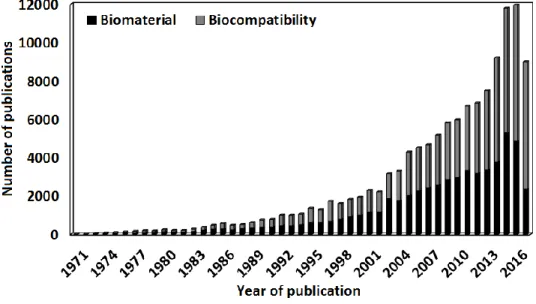
biomaterial and biocompatibility have been evolving since they first started to be found in literature around 1970. Since then, their use has been growing as can be noticed in Figure 1.1. As the biomaterials science field expand new insights keep arising, that creates a pressing need for reflection and constant adjustment of the definitions, so those should be regarded as dynamic
Chapter 1 - Introduction
instead of dogmatic. Also, the definitions can be subdivided according to the context, because for example the concept of biocompatibility regarding an implant is surely different from when considering a polymer-nucleotide conjugate, and the attempt to make a definition that comprises such different biomaterials, can result in a hollow one.
Figure 1.1: Evolution of the number of publications mentioning biomaterials and biocompatibility from 1970 to 2016. Source: Scopus; keywords searched: “biomaterial” - “biocompatibility”; search date: 30/12/2016.
1.2.2 Graphene-based materials
Carbon has been observed since prehistoric times in the form of soot, charcoal, graphite and diamond. For example, the usage of graphite has been traced to before 4000 BC, when the Marican, Boian, and Gumelniţa cultures in Europe used it to paint pottery. [20-24] Obviously,
ancient cultures did not realize, that these substances were different forms of the same element,
[23, 24] because the identification of carbon as an element only millennia after was worked out step
by step by R.-A.-F. de Reaumur, H.-L. Duhamel du Monceau, Torbern Bergman, C. W. Scheele, C.-L. Berthollet, A.-L. Lavoisier, and others. [24] In 1789, A-. L. Lavoisier listed “Carbone” in his “Traité Elémentaire de Chimie” as one of the newly identified chemical elements, whose versatility was already known since it had been shown that it was the elementary component of both diamond and graphite. [25, 26] Since then, more allotropes of carbon have been discovered and studied, ranging from amorphous carbon, to fullerenes (0 D), graphene (1D), and nanotubes (2 D). [26-28] Graphite ore has been found and mined in England since the 16th century. One of its
Advances in GBMs and their composites with focus on biomedical applications
uses was to mark sheep, and because of that in 1789 A. G. Verner named it after the Greek word “graphein”, which means “to write”. [21, 29] Since the development of the pencil industry in the
18th century, graphite has been one of the most widely used materials to write. [21] Due to its
layered structure when mechanical friction occurs between the paper and graphite in the pencil, graphite flakes are delaminated becoming attached to the paper. Thus by the simple act of writing, we have been on the way between graphite and graphene since centuries ago, but that only started to be considered recently, due to the importance that graphene has been achieving. [30] Reviews
on graphene history [29, 31] report the firstly produced monolayer graphene-based material (GBM)
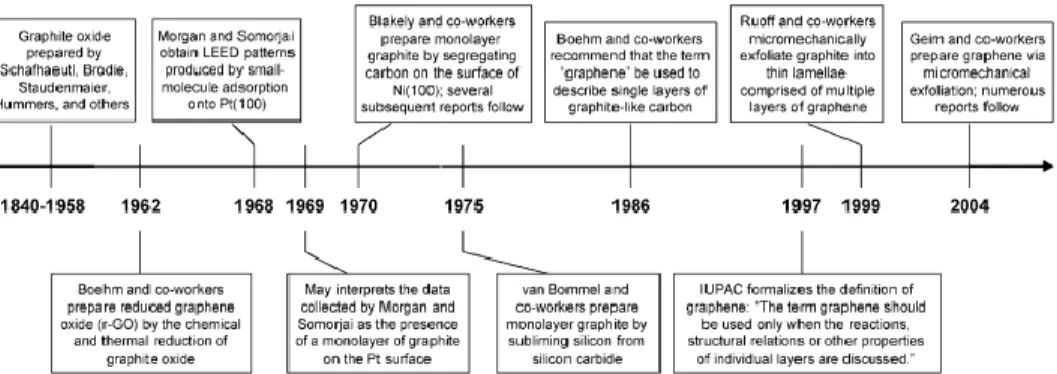
to be graphene oxide (GO). Since around 1840, Schafhaeutl, Brodie, Staudenmaier, and others were studying the intercalation (insertion of small molecules in between the graphite layers) and exfoliation of graphite with strong oxidizing acids (Figure 1.2). [29] In 1948, G. Ruess and F. Vogt, observed few nanometers flakes of GO by transmission electron microscopy (TEM), being these studies continued by the group of Ulrich Hofmann, which in 1962, together with Hanns-Peter Boehm identified some GO fragments as monolayers. [31] The later, proposed the term
graphene for the first time in 1962 in the following terms, “The ending -ene is used for fused polycyclic aromatic hydrocarbons, even when the root of the name is of trivial origin, e.g. naphthalene, anthracene, tetracene, coronene, ovalene. A single carbon layer of the graphitic structure would be the final member of infinite size of this series. The term graphene layer should be used for such a single carbon layer.” [32] In 1997, IUPAC recognized graphene by including the
following recommendations into their Compendium of Chemical Technology, “previously, descriptions such as graphite layers, carbon layers or carbon sheets have been used for the term graphene. Because graphite designates that modification of the chemical element carbon, in which planar sheets of carbon atoms, each atom bound to three neighbours in a honeycomb-like structure, are stacked in a three-dimensional regular order, it is not correct to use for a single layer a term which includes the term graphite, which would imply a threedimensional structure. The term graphene should be used only when the reactions, structural relations or other properties of individual layers are discussed [emphasis added].” In 1999 Ruoff and co-workers micromechanically exfoliated graphite into thin lamellae comprising multiple graphene layers. In this method, lithographic patterning of highly ordered pyrolytic graphite was combined with oxygen-plasma etching to create pillars, which were converted into the thin lamellae by rubbing.
[29] In 2004, Geim, Novoselov, and co-workers using a similar micromechanical approach,
followed by repeated peeling of flakes from graphite with scotch tape, finally achieved a single layer – graphene, which could be located by optical and electron microscopy and its electric-field effects characterized. [33]
Chapter 1 - Introduction
Figure 1.2: Timeline of selected events in the history of the preparation, isolation, and characterization of graphene. Reprinted from reference 29, with permission from Wiley, Copyright (2016).
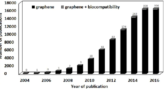
Graphene’s outstanding electronic, mechanical, and thermal properties, amongst others, surprised researchers and started a whole new field of research that has been growing ever since, due to its vast potential applications. [34-38] Around 2009 several technological companies, like IBM, Samsung, and Fujitsu, started investing on graphene-based technology. [21] In 2010, Geim and Novoselov were awarded the Nobel prize "for groundbreaking experiments regarding the two-dimensional material graphene". [39] Realizing the potential of graphene, several governmental agencies started investing in graphene from 2011 on. The outputs of industry and governmental investment have been arising in the most diverse forms up to date, as for example graphene-based inks, water desalinators, transistors, batteries, supercapacitors, sensors, and displays, amongst others. [21] This means that currently and each time more, graphene will be widespread in the
environment, however, it can be observed from Figure 1.3, that only a tiny fraction of the research on graphene field is focused on the biological field. The first publication regarding graphene biocompatibility that could be traced, was from 2008, and shown that mouse fibroblasts presented a normal morphology and grew at the same rate on top of a graphene paper, as at the surface of tissue culture polystyrene. [40] However, graphene-based materials (GBMs) can also be dispersed
in solution, present different dimensions, degree of oxidation and functionalizations. With the arise of new studies of graphene-based materials biological properties, it could be concluded that most studies report cell viability decreases inferior to 20% after exposure to GBMs concentrations around 10 μg mL−1 during 24 h or longer. Also, the in vivo effect of GBMs depends on their physical–chemical properties, concentration, time of exposure, and administration route, and also on the characteristics of the animals used. Most studies report no occurrence of adult animal death [41], with an exception for the death of a mice due to intravenous administration of 0.4 mg GO [42]. However, there are some reports of GBMs accumulation and histological findings associated with inflammation, and, more rarely, fibrosis. Small sized GBMs